
Joel SHOEMARK
-
Posts
170 -
Joined
-
Last visited
Joel SHOEMARK's Achievements
")


-

Badly Corroded Yeti rear brake discs - is this normal ?
Joel SHOEMARK replied to maisy's topic in Skoda Yeti
I think this is pretty common with most cars these days. My last car was a Subaru WRX. I replaced the rotors with every set of brake pads. I think it's something with the brake pads compounds containing more metal. Rotors have always been consumables but they are just getting consumed quicker these days. I also don't think stabilty control helps these days. Unrelated vehilce I know but to demonstrate the effects of stabilty control. Newwe Land Rovers have a thing called trailer sway control. The idea is the stability control detects sway of the trailer and counteracts it with brakes. The system works so well though the driver often cant detect sway. So when a trailer like a caravan is loaded wrong like too much weight to the front or rear the trailer would normally cause the vehilce to sway, sometimes uncontrolably. Just note some Land Rovers have air suspension that raise and lower to keep a standard ride height so you don't see vehicles sagged or raised in the rear from badly loaded trailer. The issue comes when the system has been working so hard to counter the sway of the trailer the brakes are worn out within 1000km. Happy Days. -
S on the way into a corner a D on the way out.
-
I can't remember how I secured it. Everything came in the kit. Yep, Just plugged it in. I did have the ignition and accesorys turned off. You still need the vehicle prorgammed for the rear park sensors to turn off. Happy Days
-
Hey mate, If you look at photo 17, just before I start puting panels back in,, you can see the cable runs down to the grommet in the left hand side. The bracket that the 13 pin plug mounts on is a seperate peice. It actually allows the plug to swing down into place. It then swings up out of the way when the hitch is removed and the cover on. Without the bracket on the plug fit through the hole and there is another grommet that is part of the loom itself. Happy Days.
-
-
<a href="http://s560.photobucket.com/user/joel0407/media/Disco/2031392C-11FD-4508-A544-5D41EF280142_zpsj9jv0tlm.jpg.html" target="_blank"><img src="http://i560.photobucket.com/albums/ss50/joel0407/Disco/2031392C-11FD-4508-A544-5D41EF280142_zpsj9jv0tlm.jpg" border="0" alt=" photo 2031392C-11FD-4508-A544-5D41EF280142_zpsj9jv0tlm.jpg"/></a>
-
I've been following this thread for a while. I think it's about time I post up my Land Rover Disco 2. http://s560.photobucket.com/user/joel0407/media/Disco/2031392C-11FD-4508-A544-5D41EF280142_zpsj9jv0tlm.jpg.html
-
DSG Paddles; yes or no?
Joel SHOEMARK replied to Kansalis's topic in Skoda Octavia Mk II (2004 - 2013)
x3 on S mode being pretty useless on the Diesel. I use S coming into corners and then change to D at the Apex on the way out. Happy Days. -
Well. Over 2500km down and the lights are working OK with 100w halogen bulbs in them. To ejstubbs. Yes I stuck with the transistor circuit. Mainly because I didn't want to get a CANBUS error. As far as I know all loads are monitored. As you say this circuit should be more than able to handle a couple of hundred milliamperes but if the system isn't expecting any load then it might generate an error and turn off that system. I can only confirm it doesn't see 2 milliamperes. As for wiring the relay direct, experiment at your own risk. I would at least recommend using a resistor in series to at least limit the current draw. I say the light are only working OK as the HID kit I ordered didn't turn up before I left. This the first time I have run halogen driving lights in over 6 years and while they are good for halogen, they have nothing on HID. Happy days.
-
This is them. http://www.ebay.com.au/itm/like/300960171844?lpid=87 They do look so much better than the flat strap that is sold as light support strap. I think hella call theirs 2 point mount. It's just flat strapping with slotted holes. You get the light where you want it and do up the bolts in the slotted holes, holding the strap at the set length. Happy Days
-
I think the vibration is from the softness of the plastic. I have no doubt of the strength to hold the lights. It's just a little flexable and allows the plate to move. I have also added a couple of stays of the top of the lights that completely stop that forward/back movement of the top of the lights. I'm also into RC Helicopters so I crossed the hobbies a little and use some heavy duty (RC heavy duty) ball joints from the light to the car. The ball joints are connected by about 3mm threaded rod with a carbon fibre tube. The carbon fibre tube just hides the thread and looks cool.. Happy Days.
-
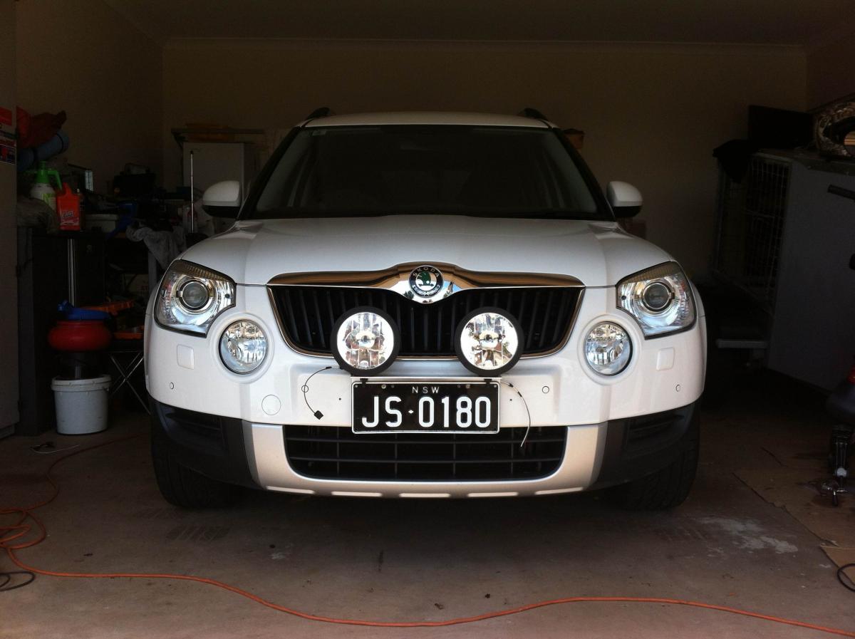
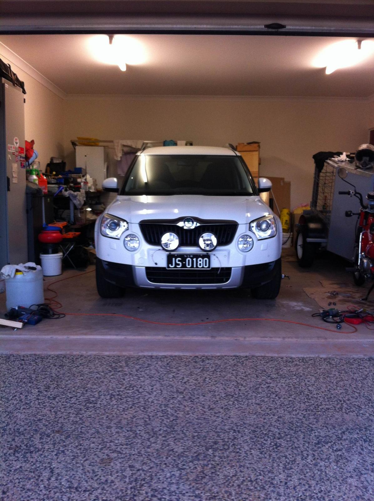
Yeh mate, Thats pretty much what the bar thing is. It's just a peice of alloy angle thats pollished up. I has to cut the tube peice of the front because my lights are very low and wouldnt fit. It was only welded on the bottom side so my cutting is not visible unless someone gets lower than the lights. As for mounting. I had the whole bumper off. Its so easy when you have the workshop manual. The plate had holes for 4 x M8 bolts but the silly thing was the lower 2 were only half way down the plate which is full number plate height. I went against my better judgement and just used the provided holes, only to find it was not rigid enough to stop the lights vibrating so I had to add 2 more at the bottom. I'll post pics but just imagine 3 x M8 bolts on either side, spaced out from the bumper to match the curve. Dont worry about whats behind the bumber. It's just foam. I want to put all the pics together with instructions and information but here's a sneak preview.
-
Well this has to go down in history as the longest driving light install ever. I have enough pics for others that want to try their own install but I'm leaving for a 2 week trip tomorrow, 10,000km to drive. I'll get them uploaded when I get back. I have to say I'm pretty bloody happy with the result. These are all wired up but I'm waiting on a HID kit. If it doesn't arrive I'll put the 100w Halogens in.

-
Ok the last 2 days have been rubbish to say the least. Well until about mid day today anyway. I have done a bucket load of searching, posted questions on several forums and sent a few Private Messages to people who had posted pictures of Skodas with driving lights. I was hoping that other Skodas might just use the same colour code with the head light wiring. Still no idea what wire was the high beam wire so I could use it to activate the relay. All the wiring is sealed so I cant just test from the back of the plug. If I unplug connector, the Contorl Unit detects a break in the system, throws a code and turns off the light so I cont test from the end of the unpluged connector. I managed to find the relay inside the head light and check the wires on the back. Power was all over the place and never anymore than 2.5v. I was pulling my hair out and starting to think it wasn't going to be possible. A mate had suggested that I run a kick switch to the floor and operate the driving lights seperatly but that would annoy me to no end. So late last night I found a site that had a downloadabe copy of the workshop manual and sold the key to operate it for 9.99 pound. I down loaded it over night and it turned out to be the best money I have ever spent on the Yeti. I spent a couple of hours studying the circuit diagrams and by mid morning I was convinced that it couldn't be done. Turns out the Bi-Xenons have there own Control Unit. It monitors individual wheel speeds, steering angle, rear axle heigh to name a few. Turns out its a very cleaver unit. It receives Data from the main ECU and power then does it's own thing so there is no power wire as such going to the unit to open the shutter. It has it's own power and opens the shutter when it's told to via CANBUS data. Then I considered that some people sell change over headlights from Halogens to Bi-Xenons. I checked the circuit diagrams for NON Bi-Xenons and found there is a wire from the power control unit that supplies power for high beam. Low and Behold it still workes even though everthing else is settup for Bi-Xenons. So I now have a high beam power wire to activate my relay for the driving lights. It's Yellow with a grey line on the left side head light. I beleive ut's differnt on the right. Happy Days.
-
One side of each the coil and the switch are joined together and go to positive. So lets say 30 and 86. The other side of the switch (87) goes the the auxiliary driving lights. That leaves 85. 85 is the other side of the coil. Now if 86 is the positive side then 85 has to be negative. If you work through the pictures you'll see this is the leg that most of the components are built on. The transistor basically becomes a switch for this leg. Sent from my iPhone using Tapatalk Happy days