gazz3000
Finding my way
-
Joined
-
Last visited
Everything posted by gazz3000
-
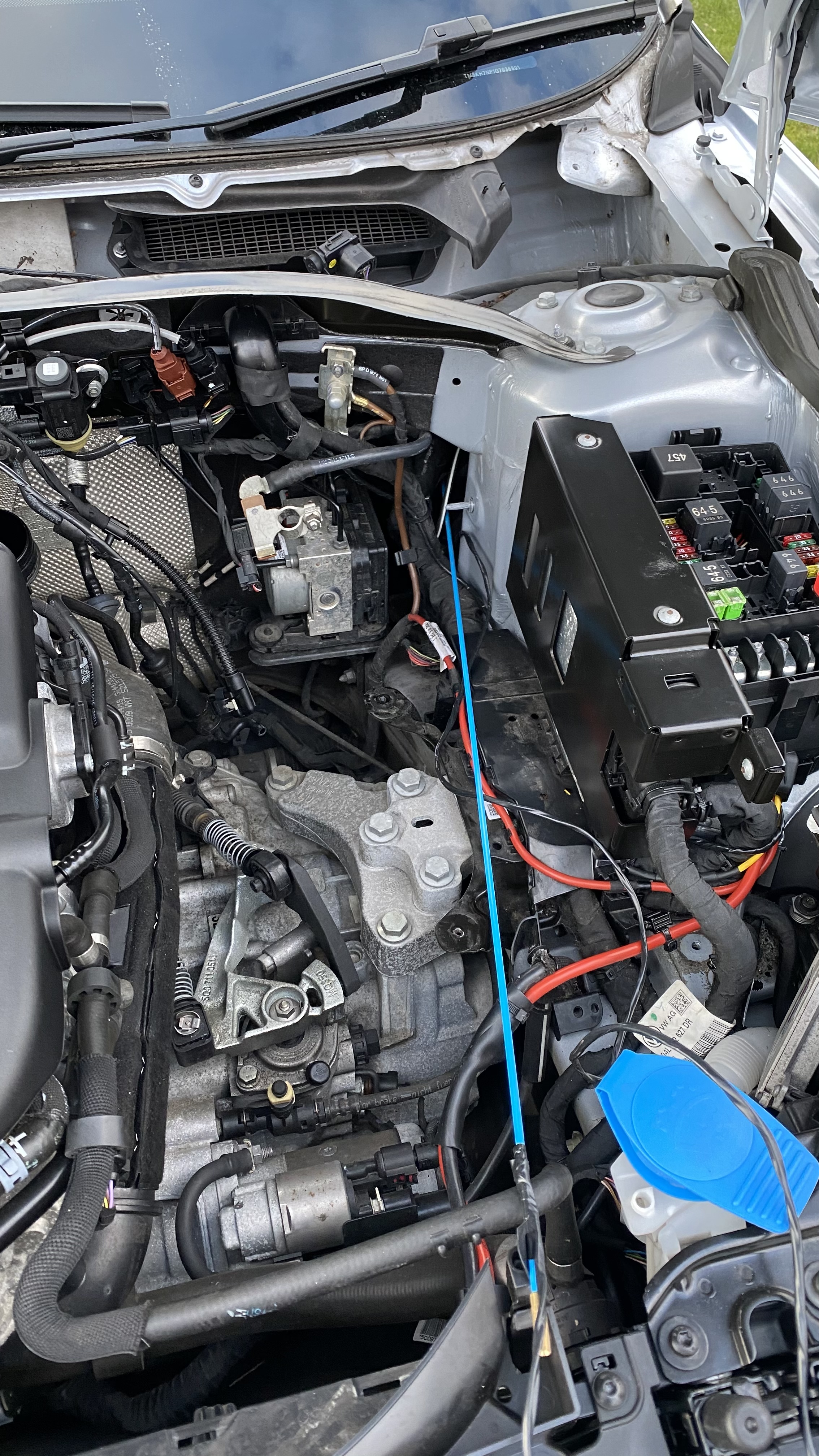
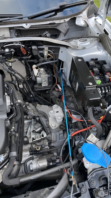
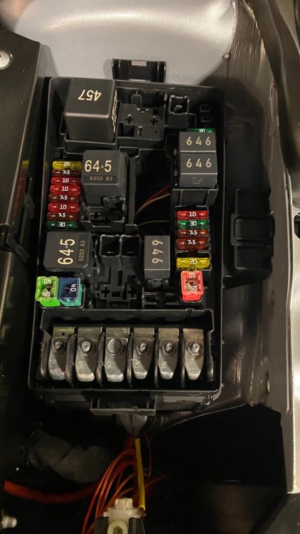
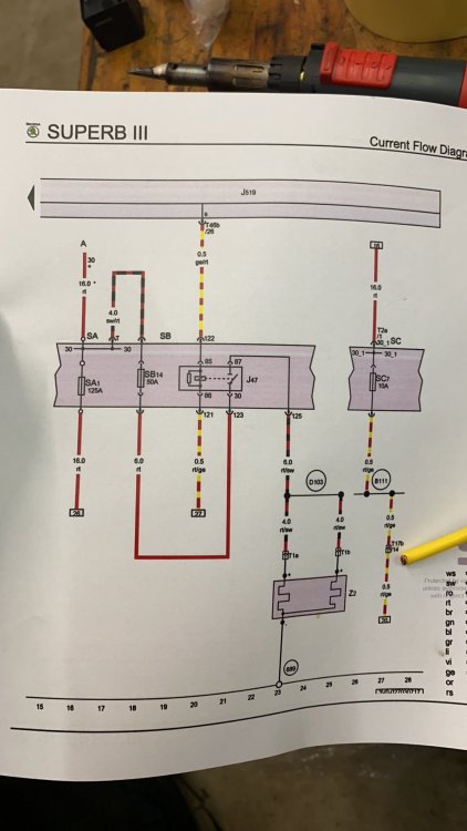
I will do when I’m home, I’m on holiday at the minute for a week is the 3rd photo down not clear enough? If you can’t wait I can always tell you what each component is if need be!
-
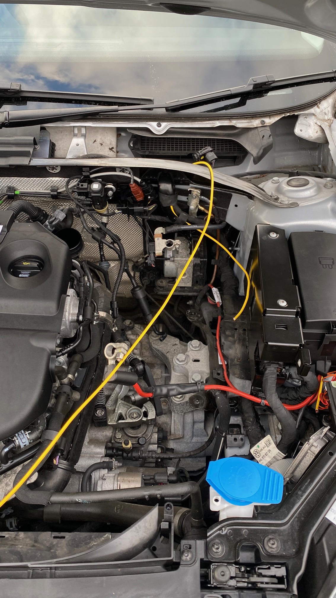
Yes mate, see the photo attached! House cable rod straight through the grommet was the perfect diameter to take the two cables, also make sure you go high up on the groomer that way when the water runs off the screen and out of the scuttle it won’t make its was into the cabin!
-
Sorry pal that was a miss type, I did use 2x number 4, I went off all the invoices I could find but that one was missing! sounds good so far what you’ve done! Have all the part numbers been good so far for you??
-
I’ll second that one!!
-
Everything is accessible once the screen is in pal! If you need any help on the wiring then let me know! I’ll blast you the wiring diagrams over! FYI the earth connection is above the interior light at the front of the roof liner and the two connectors for the positive side of the screen are under the scuttle panel, perfectly accessible if your happy taking the scuttle back off once the screen is fitted!
-
I've finally finished the install now all. Ive created a new topic for it to save hijacking this one again! sorry to the OP! Cheers all!
-
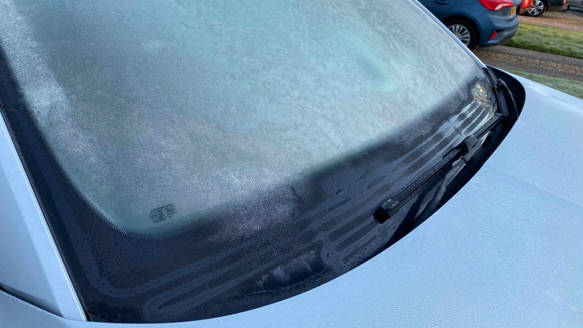
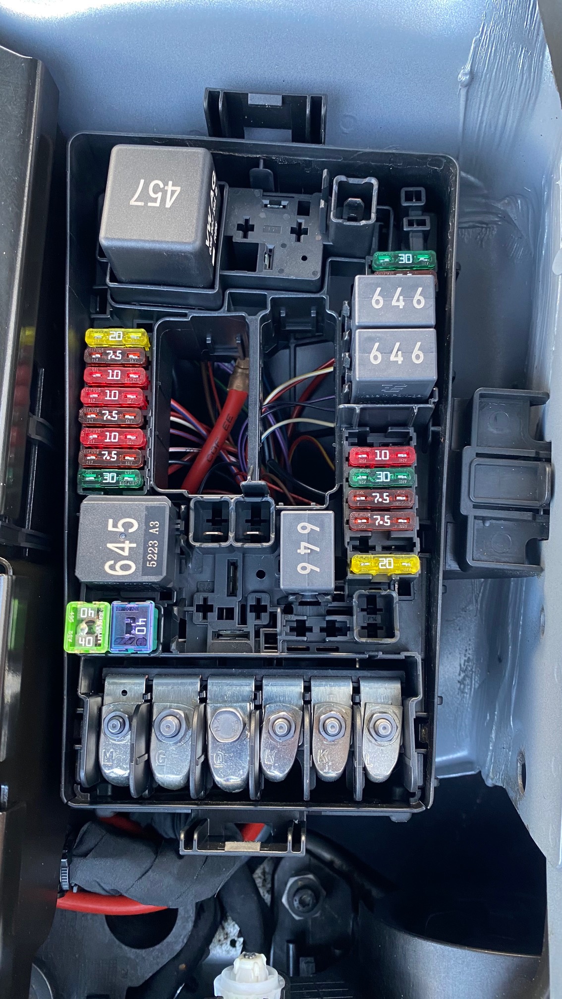
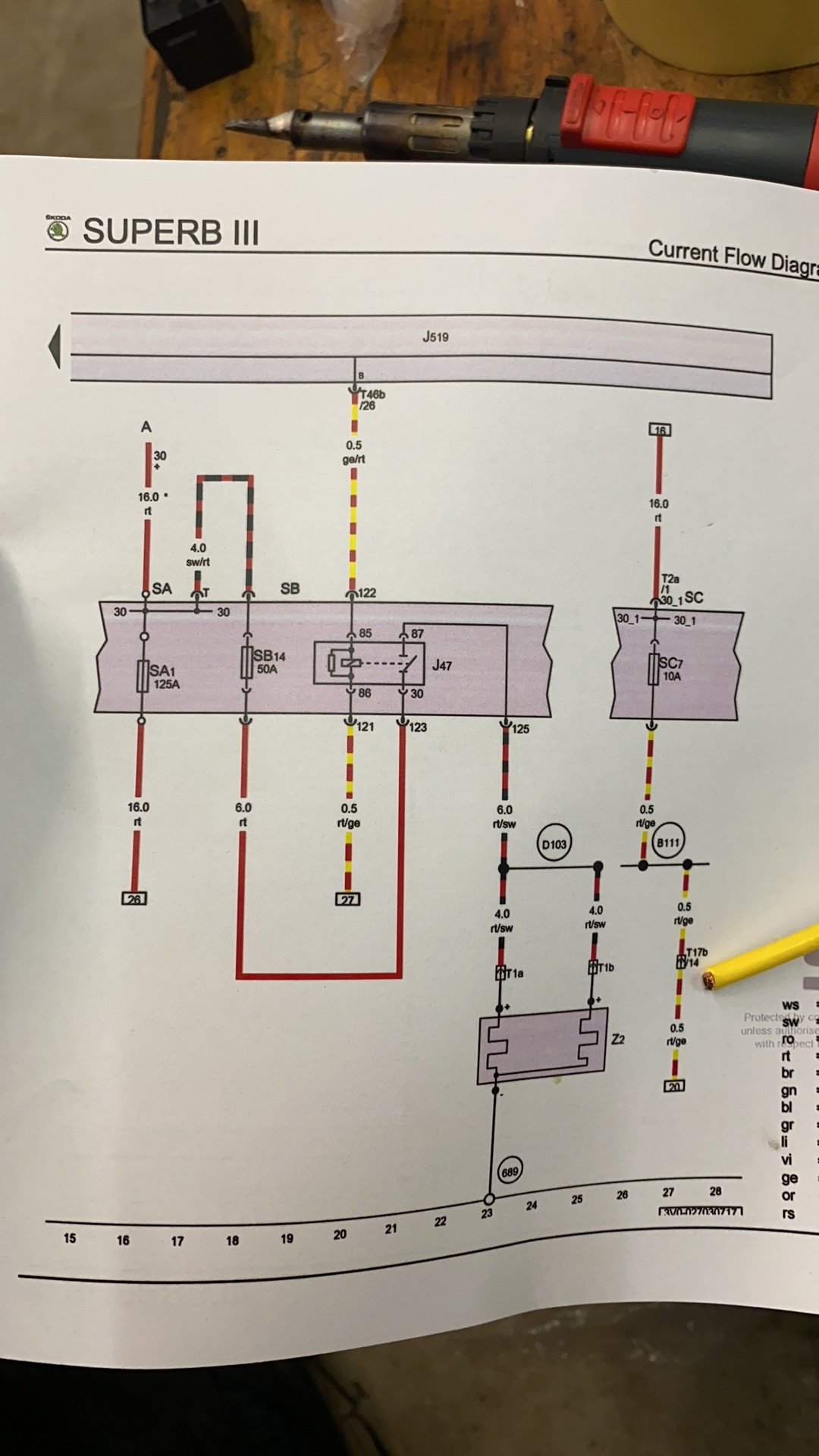
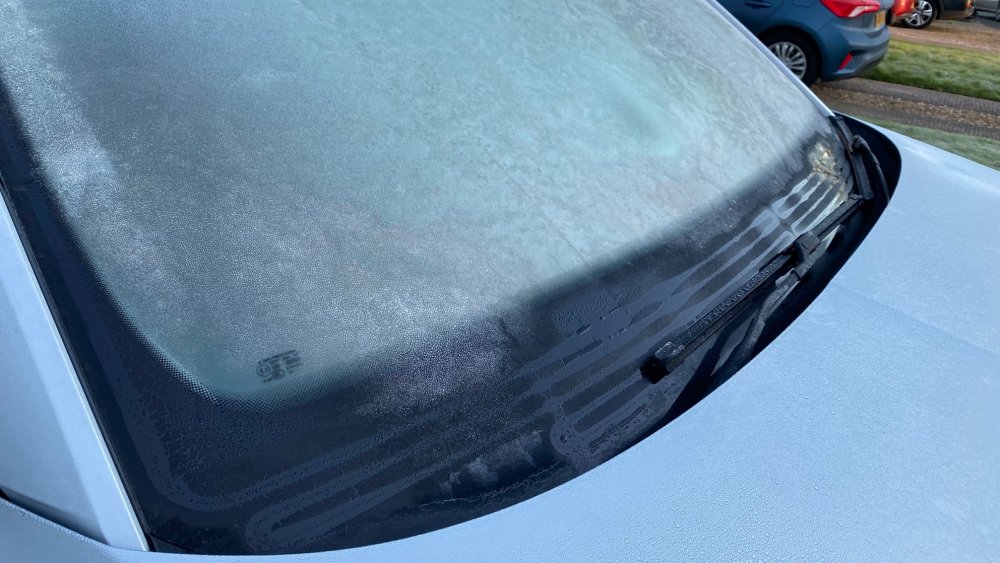
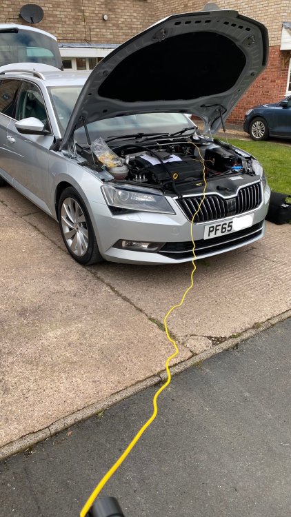
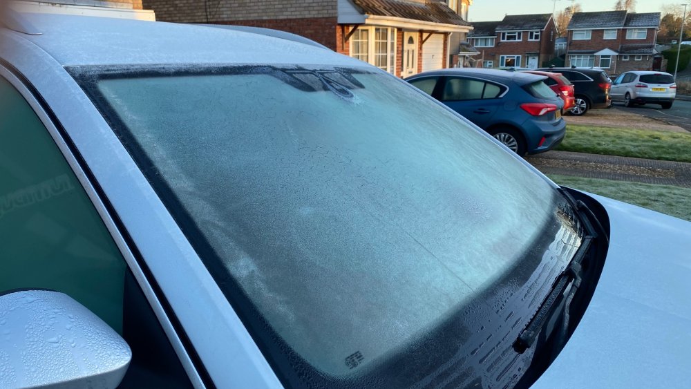
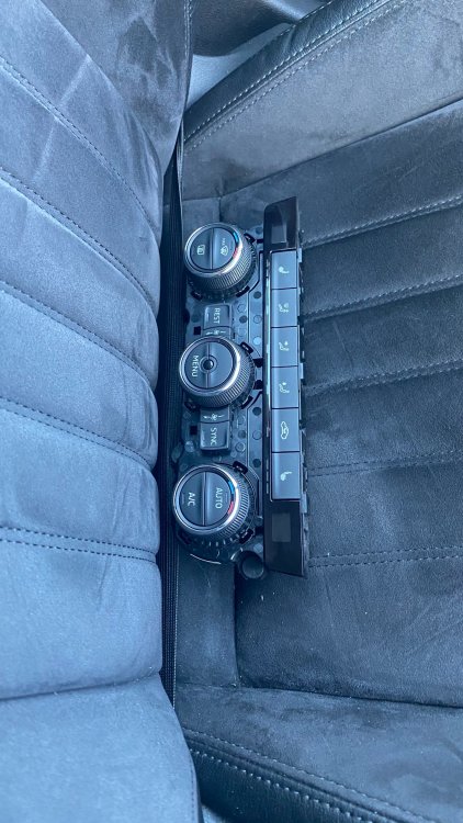
Hello all! This is my first time writing something like this so forgive me if I seem repetitive or Firstly let me say this has been a great challenge from start to finish and what a difference it has made already and I’ve only had the screen in for 5 days as of writing this (27/02/2021.) The whole reason for wanting to fit the heated screen was down to the fact that every winter morning I would get into the car and the screen was misted up and would take forever to clear both the ice and mist on the inside. Parts list for this project is as follows: 1) 000979986A – 6mm repair wire. Approximately 5m long. £6.80+vat 2) 000979985A – 4mm repair wire. Approximately 5M long. £ 8.57+vat 3) 071973851 – Housing (connectors for the heated screen positive connection.) £5.59+vat each (x2 required) 4) 000979425E – 6mm wire with terminals on for relay connection terminals 30 & 87 - £8.64+vat 5) N91186305 – 50A fuse for position 14 in under bonnet fuse box - £5.69+vat 6) 5Q0937507D – Relay plate for the heated screen relay in under bonnet fuse box - £3.79+vat 7) Used under bonnet fuse box from Ebay with all the relays, fuses and terminals still in the housing - £16.66+vat 8) Used Heater control panel from Ebay - £62.50+vat (matching PR codes to your current vehicle apart from finding the correct PR code for heated screen to add to your current codes for the correct part number (3V0 907 044 T YMS for my car) 9) 3V0 845 011 AD NVB – Heated windscreen from TPS - £448.28+vat 10) Soldering iron and solder 11) Heat shrink of varying sizes and colours (optional but it was the best was I found of waterproofing the connections under the bonnet. Might I add that none of the connections that I’ve made have been twisted and taped together! That’s just not done in my eyes, in my opinion you’re asking for trouble if you even contemplate doing that! 12) Electrical cable rod to get the wiring through the grommet in the firewall to make internal connections. So I started off by first making sure that the body control module was the same as one from a Superb that had a heated screen so that I knew that the internal relay was present in my control unit for outputting an earth to the switched side of the screen relay. Luckily it was the same as the superb with a heated screen so onward I went. I started by fitting up the relay plate in the under bonnet fuse box, the 6mm repair wire comes with two terminals on it (one either end) one end went into position 123 and the other in 125 of the relay plate & the wire was then cut in half giving me two long tails read to connect as required. The wire in position 123 was connected one of the cables I removed from the second hand fuse box and was put into one of the openings in fuse 14s location. For the other terminal in fuse 14 I again removed one of the fuse terminals from the used fuse box and put this into the other side and connected it to a Terminal 30 connection post on the underside of the fuse box. I then extracted two of the 0.5mm relay terminals with tail wires still attached from the used fuse box and inserted them into positions 121 & 122 of the relay plate. With the power connections made and the tails for the other three wires long enough I attached extension wires to them and started routing the 6mm wire from the under bonnet fuse box along the existing wiring loom and up to under the scuttle panel where the connection would be made for the positive connections on the bottom of the screen. The other two tails for the power and earth for the changeover of the relay were loomed together and also run alongside the existing wiring loom to the grommet in the firewall. I used a small spike tool to make the smallest of holes so that I could screw the threaded end of my electric cable rod through the grommet and attached the tails to it using electrical tape. Pulled the tails through the fire wall and because I’d made such a small hole to begin with the rubber just closed up around the new wiring no problem at all! If the hole hadn’t have closed up like it did I would have put a small smear of black silicone over the opening to make it water tight again. With the glove box removed and the left hand end of the dash board removed (Right hand drive car) I could access the new wiring that had made its way perfectly to where it needed to go (stroke of luck it ended up where it was to be honest rather than having to search everywhere for it and re rout it inside the car). Again calling on the used fuse box I removed one of the fuse terminals with a long enough tail on it and inserted it into the fuse box behind the glove box (this saved routing a wire from the left side of the car and taking it all round the back of the dash to then have to find connection B111 for the heating circuit fuse and tagging into that) and used a separate 5A fuse supply for the trigger side of the relay instead of fuse 7 on the drivers side fuse box. The remaining tail wire for the earth trigger from the central electrics control unit (J519) was next. This went to terminal 26 of the 46pin connector (middle plug) of the J519. I had a terminal left over from a job at work which was the correct one for this purpose which is why I’ve not listed it above because I couldn’t find the part number for this but if you order parts from TPS then they’ll be able to have a look on ETKA for the wire you’ll be needing. Once this was connected and the two fuses were installed and the relay was installed I turned my attention to the connections under the scuttle for the screen. These were probably the easiest connections to make. As mentioned above the repair wires come with two terminals already crimped on, one terminal was then pushed into each of the two housings and the locking tabs were locked in place. Normally the under bonnet plug connectors have little rubber grommets that are crimped onto the terminal and wire to make the plugs water tight. I wasn’t going to buy a bag (30 in each bag) of these for stupid money as I only needed two. So out came the black silicone with a fine nozzle on it and I filled the two open ends up and moved the wire around so that the silicone could completely fill the connector openings to make a water tight seal. Worked a treat I might add! I then found the middle of the repair wire with the two connections on it and stripped it back enough so I could divide the wire in two and make a hole big enough for the 6mm tail to be pushed through and then soldered in place. I then used a combination of electrical tape and liquid electrical tape to make sure that the connection was water tight and fully insulated from touching any earth! I then had the screen fitted by a windscreen fitting company and they connected the positive connectors up in the scuttle that I’d wired in and connected the earth side of the screen to the earth post which is located under the light in the head liner. The very next day there was a relatively hard frost on the screen which I couldn’t have been happier about for once. In I jumped and within 30 seconds I’d gone from a frosted up screen to clear and ready to go! Totally worth the work doing it and all the time in getting the correct parts and cables to do it properly! Thanks all for taking the time to read this and apologies if it seems like It’s been written by a 3 year old but it’s the first time I’ve done anything like this so I hope it helps someone else out there that’s crazy enough to do the same as me! I know next time I upgrade my car it’ll have a heated screen already fitted! Thanks for reading and bearing with me while I wittered on for ages! Hope this helps anyone else that’s crazy enough to attempt this themselves!


-
they are indeed 6mm tails! Ordered the repair wire from TPS the other day. Will be routing the rest of the wiring over the next few dinner times/nights til it’s finished
-
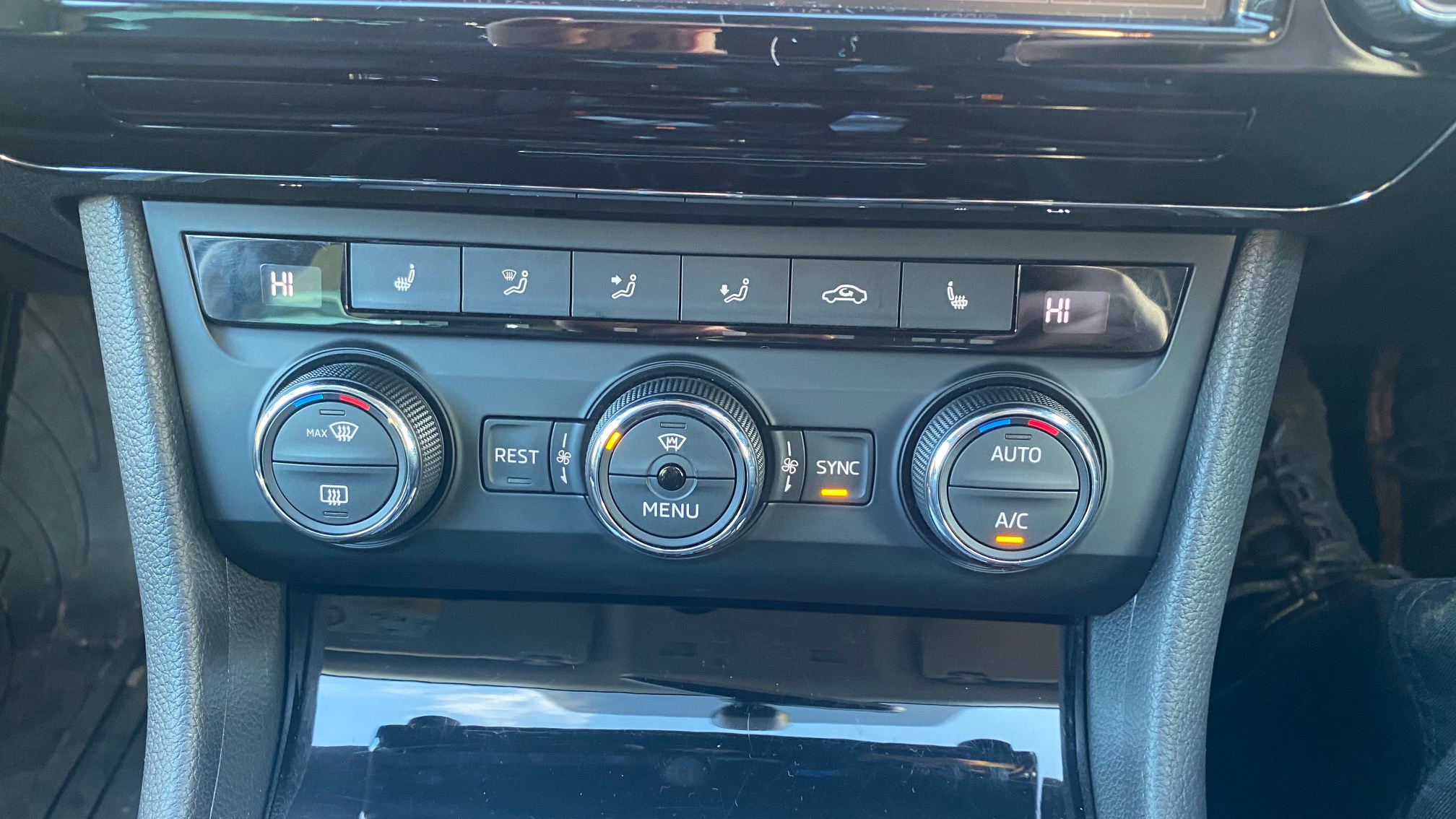
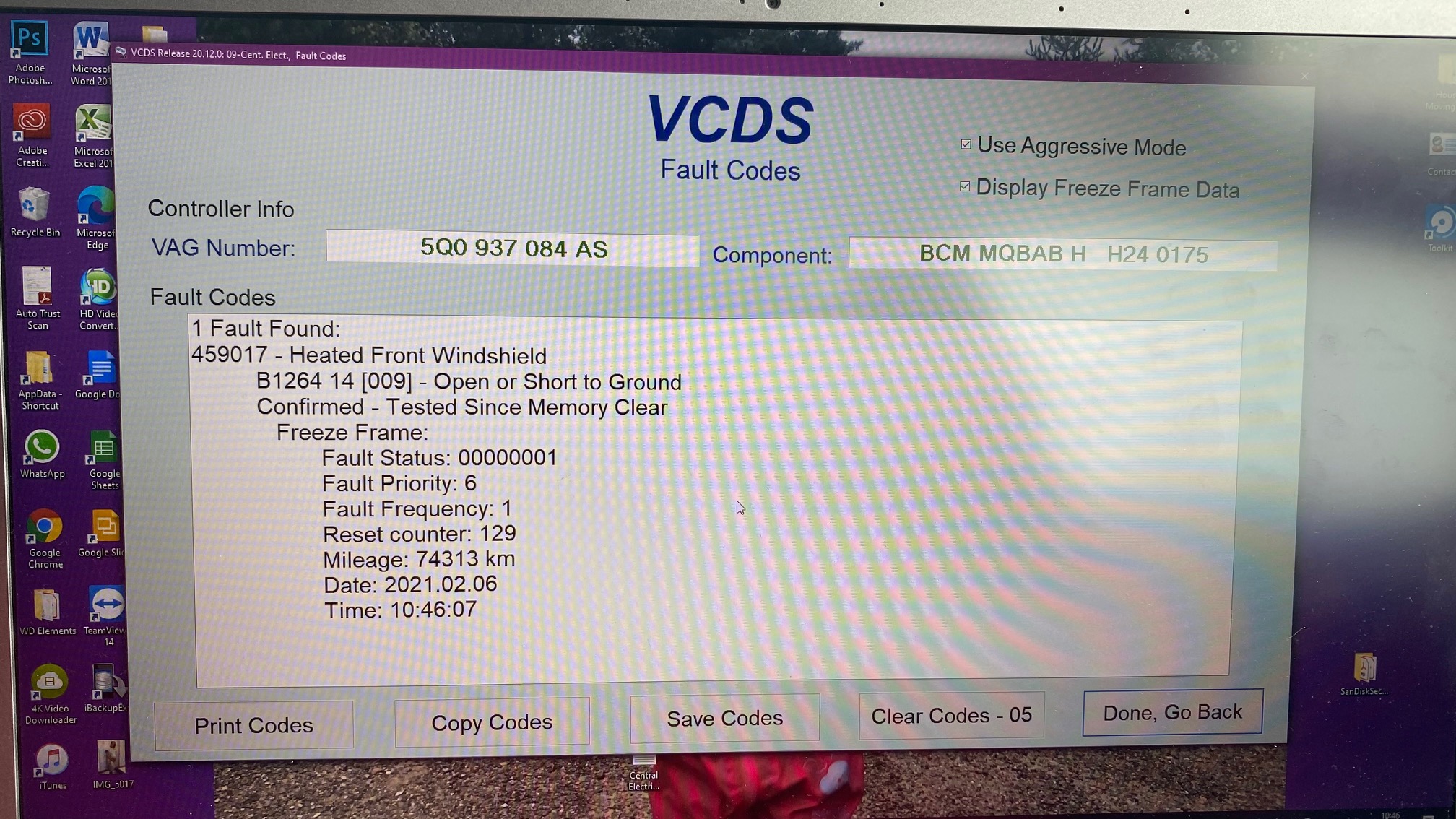
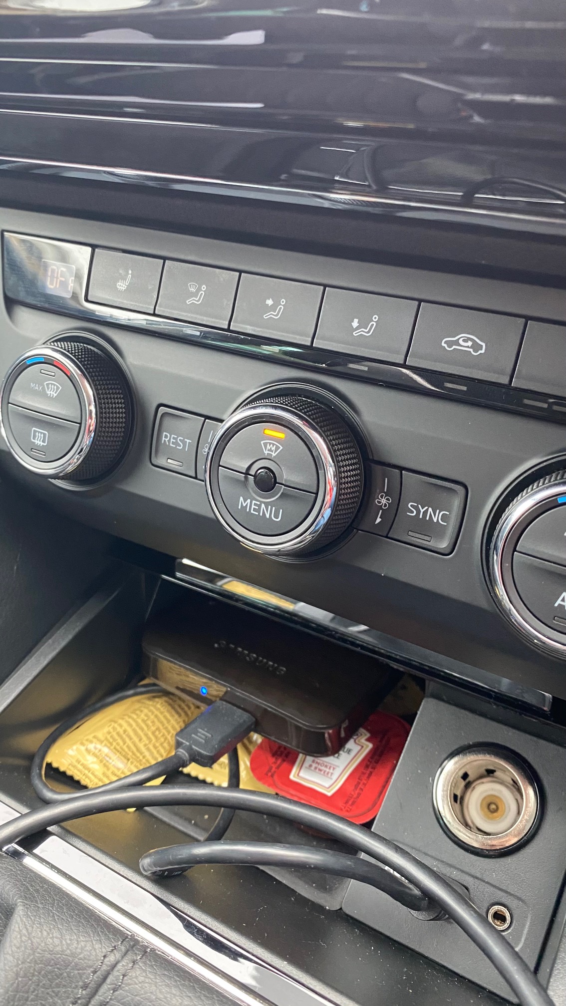
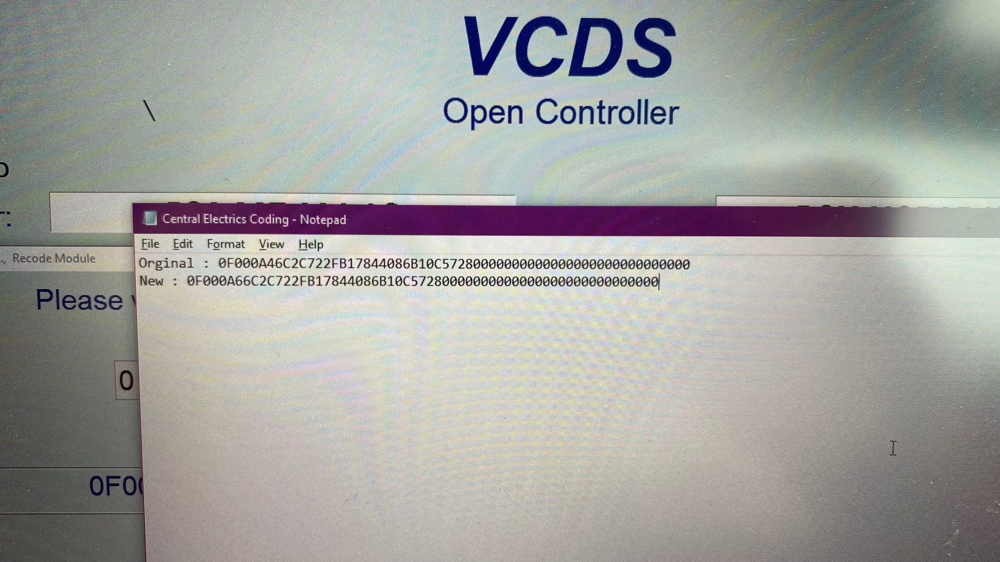
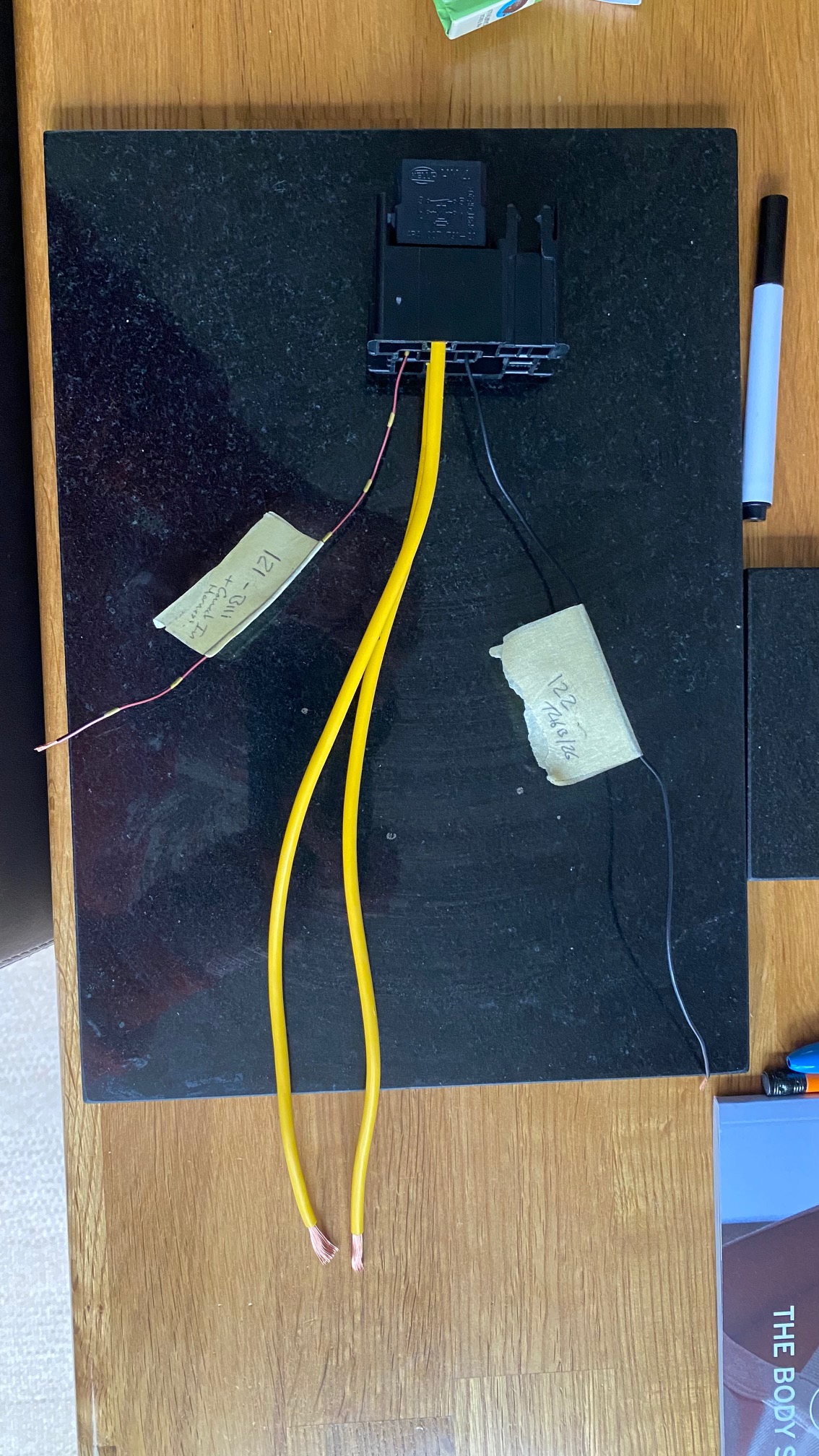
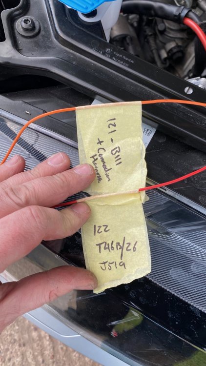
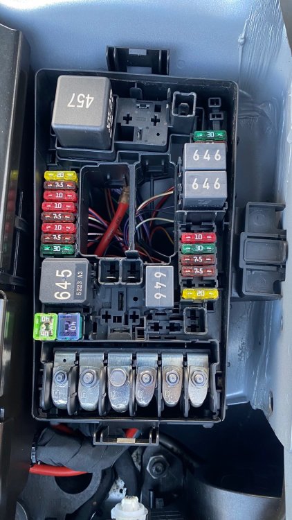
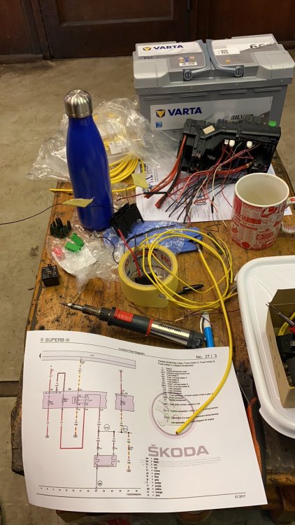
Perfect thanks, I've since been doing my homework on this subject and so far i have wired up the relay holder in the under bonnet fuse box, put in the 50A fuse to protect the circuit and also installed the terminals in position 14. Coded the central electriconics module so that when the heated screen button is pressed the light doest just go out it actually stays on now, and i also know that the relay I've installed is triggered and out puts the voltage up to the wires that will attatch to the heated screen when i get it installed. So im just getting the last few pennies together to pay for the screen and I'll post up the rest of the photos ive got then. Photos below are of pregress ive got so far, will post the rest when ive got the screen installed! Thanks for the heads up about the position of the connectors! Out with the old In with the new The bible! Under bonnet relay Coding changed from 0F000a46..... to 0F000A66 so that i get the below code


-
Where abouts were the existing wires for the screen? Were they behind the A Pillar trims or are the under the scuttle panel under the bonnet? Looking at the wiring diagram for the heated screen if the wiring isnt there then its not too bad to install. Ive been speaking to my local TPS over the past few days and im making a list of connectors/repair wires with the terminals just incase they're not there.
-
Evening gents, im currently looking into getting this sored, once ive worked out all the wiring thats needed and the control module thats required to upgrade from mine (which doesnt have heated screen but does have heated seats) ill post everything up on here for others to follow. Hopefully itll be useful to others!
-
forgive my ignorance ... as it says im new here, just thought id try and help
-
http://updateportal.skoda-auto.com/en-GB have a look on there, i updated my nav for free the other week! just choose you car and media system from the options and itll give you the correct files, follow the instructions and away you go!