burntcrisps2
Members
-
Joined
-
Last visited
Everything posted by burntcrisps2
-
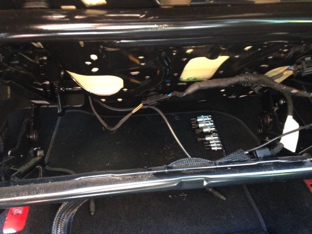
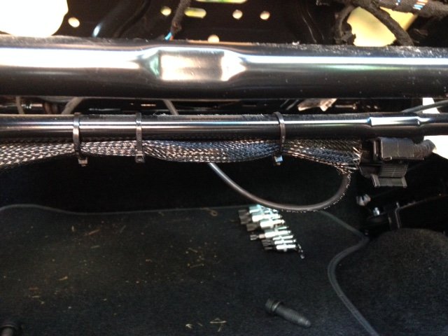
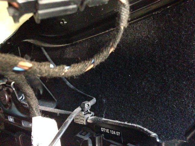
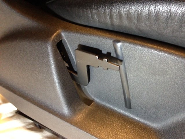
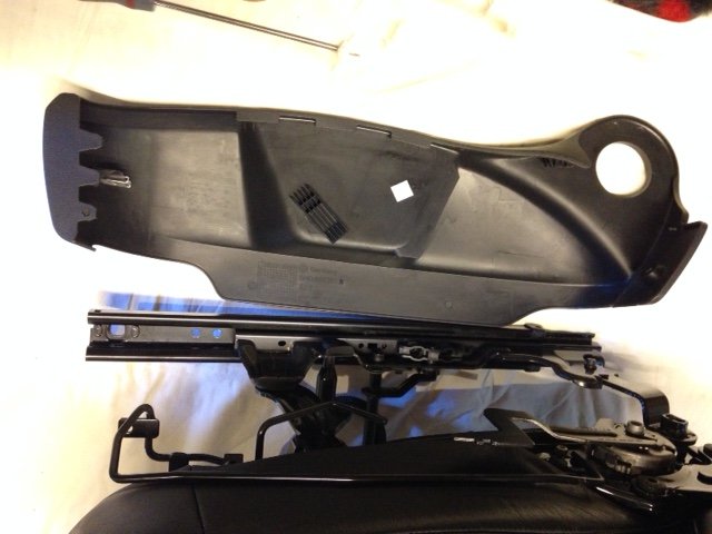
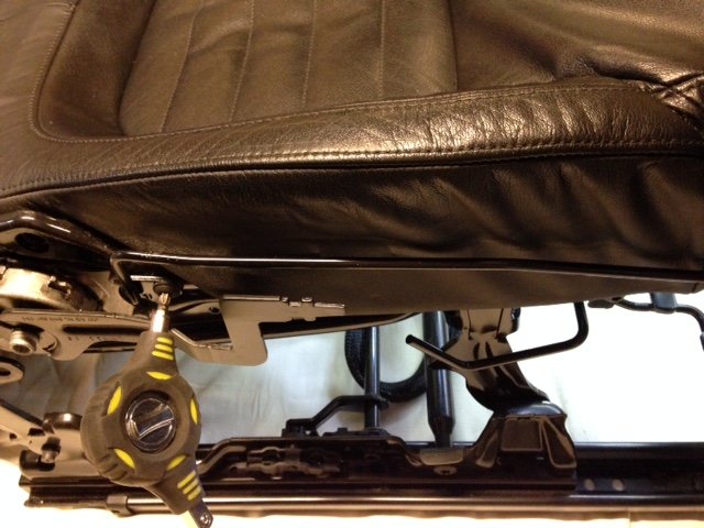
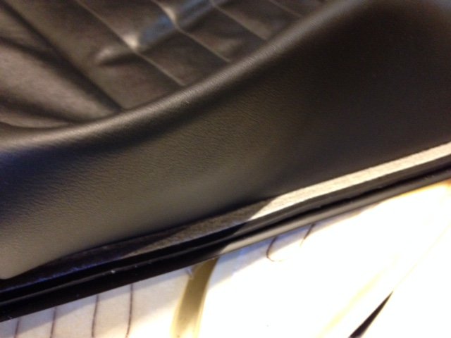
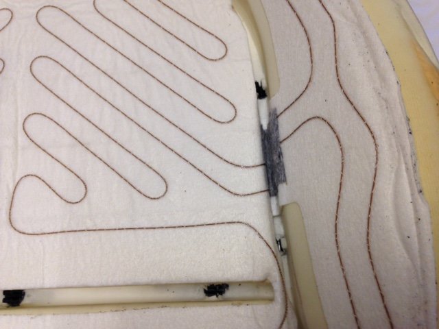
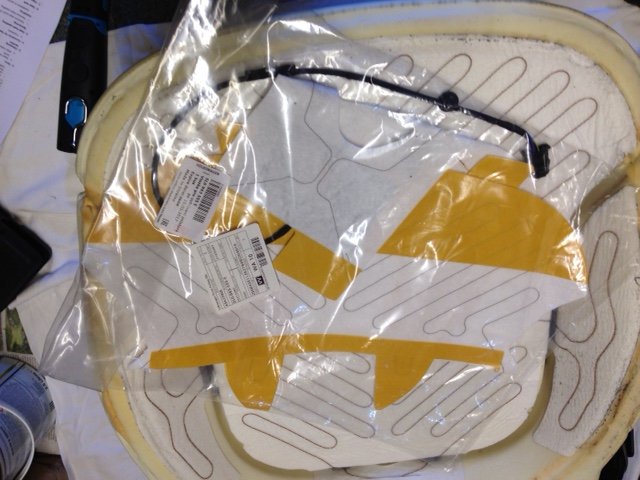
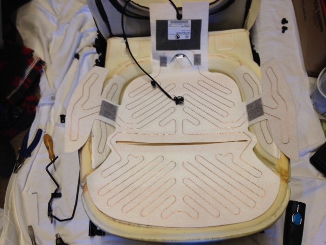
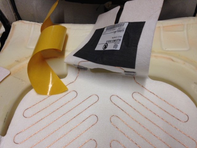
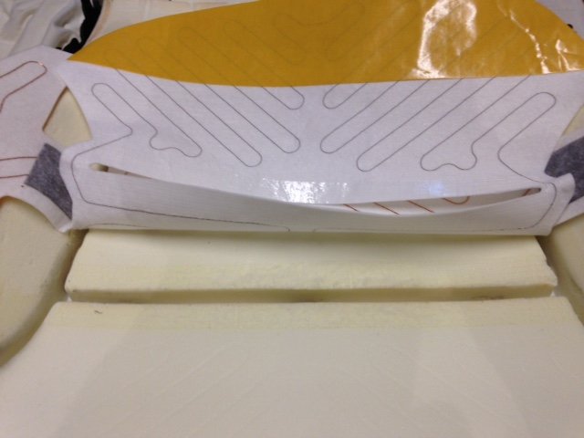
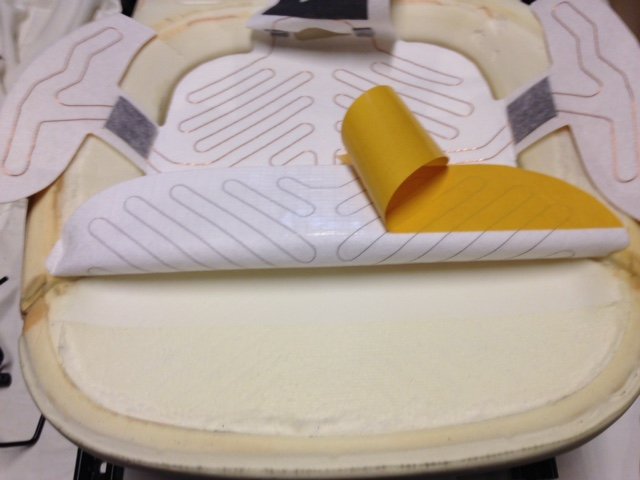
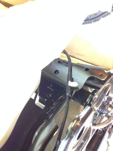
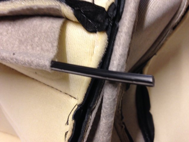
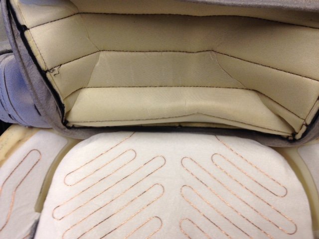
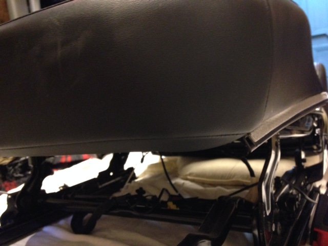
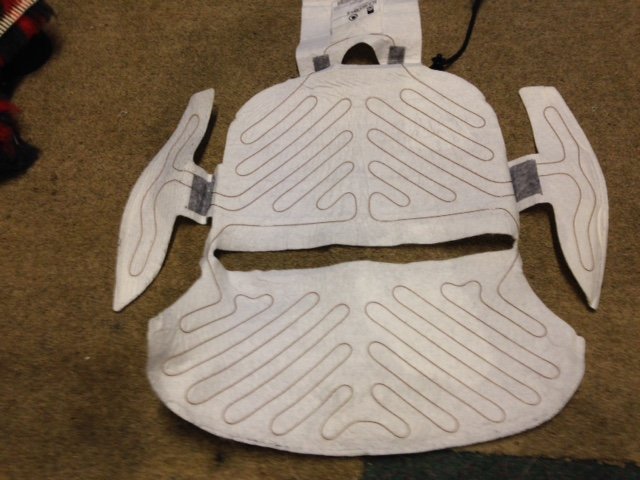
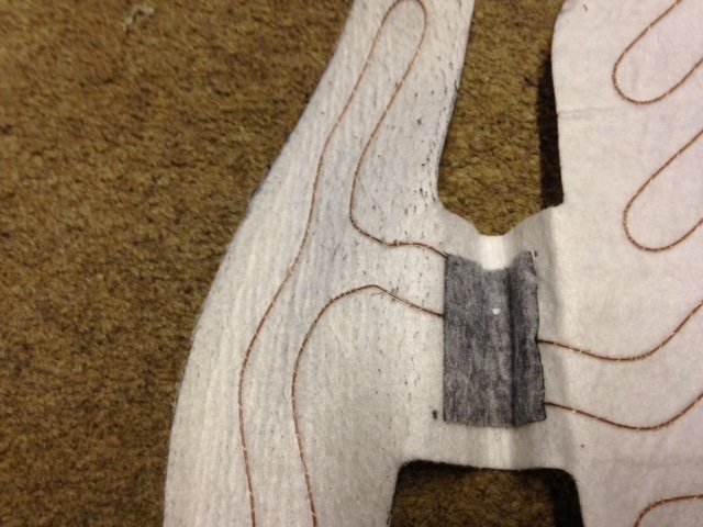
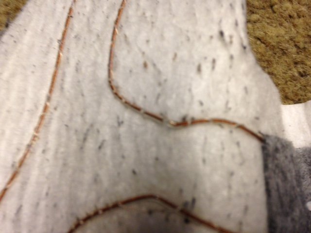
Replacing 2011 Yeti Elegance 4x4 drivers heated seat element Requirements for job 1. A replacement heating element 5L0963555E cost £40.62 30Apr2018. This is for leather seats on Elegance drivers side base heating element. NOTE: Correct item required for Model of car as different versions for Leather/Cloth seats. I believe 5L0963555D is correct for cloth seats. Quote reg/VIN # to dealer to obtain correct part. 2. M10 Spline tool for removing/replacing seat bolts. 3. M8 Spline tool for removing/replacing seatback bolts. 4. T30 Torx tool for removing/replacing some seat plastic panels. 5. Pliers to pull expanding plastic rivets. 6. Small screwdriver or bradle for removing/replacing expanding plastic plugs. 7. Large flat blade screwdriver, preferably well used with rounded corners on blade for prising various parts free and also replacing seat cover into clips. 8. Torch 9. Mirror 10. Some silicone spray to apply to the head restraint bars and mechanism. (optional but probably required on vehicle that’s 3 years or more old) 11. Another pair of hands! Will be required to help replace seat cover into clips. 12. Total time to do, about 4hrs. half a day. The drivers heated seat element failed (base of the seat), whilst the backrest continued to work correctly. So rather odd to have a cold bum, but a warm back! This happened early on in 2018 and I reviewed the procedure for doing this myself or getting the garage to fix. Whilst I couldn’t find a good guide on the web or this forum, I did have access to the Skoda workshop information for doing this and decided I would do this later on in 2018 and went ahead and sourced the replacement part from Skoda (end of April) since the cost was a mere £40 compared to at least £150 to £200 for the dealer fix. So I had in mind to do this over the summer months, but since it was so hot left till the end of September and the onset of some cooler weather, but still pleasant and dry. I have attached the Skoda workshop information, which doesn’t actually show the removal and replacement of the heated elements, but gives the overall process. When you review these you will see that metal C clips are used to hold the seat cover in place and you need to cut these C clips and replace with new ones and use a special pair of pliers to recrimp these C clips. That element alone was enough to make me think this little fix project was going to take some time to do without the special tool and also pry apart the old clips. However this was not required as you will see in the process and pictures below. This is true for our Nov2011 build Skoda Yeti and presumably later builds. This may not be the case for earlier build models. Procedure to replace 1. Fully Unlock and Park the car with plenty of room by the driver’s side, so the doors can be fully opened front and rear, with the ability to get the complete seat assembly out and past the vehicle. 2. Check if you require a radio code. Not required if factory fitted radio/satnav. Installed from new. 3. This is MANDATORY with vehicles fitted with side airbags. Disconnect the battery earth lead. (This is somewhat at odds with my lifelong electronics knowledge. It always used to be remove the Hot lead, Positive, but now most cars state it’s the Cold, earth lead. No idea why this has changed over the years.) Once this is done you will lose the trip miles information and the Clock will also need resetting when you reconnect the battery. You will also get some TCS/ESP errors on the MFD display. You need to drive some 5meters for this to reset correctly. See attached documentation. I originally discovered this when I replaced the battery end of 2017 as it was failing to hold a charge. 4. Remove the headrest. (I didn’t do this but discovered it was required when I tried to remove the seat assembly from the car. In the process I discovered the headrest was stiff to move, so removed and lubricated all the headrests (front and rear) and sprayed silicone grease into the holes and also on the shafts. Totally solved issue with all the headrests. Like new again!) 5. Adjust the seat base so it is as high as it can go. 6. Adjust the seat back so it is leaning as far forward as it can go. 7. Move the seat fully forward and remove the 2 rear bolts. 8. Move the seat fully backwards and remove the 2 front bolts. 9. Now lean the seat assembly backwards so you can gain access to underneath. 10. The Skoda info implied that it was possible to disconnect the wires under the seat base, but in fact that’s not the case. The cables all disappear into a small cut-out inboard from the front seat bolt and rail. Flip the carpet cover up and you will see 3 connectors. Oddly the outer 2 connectors remove by pulling up once locking clips are depressed. The middle one (yellow) needs to be removed downwards and you need to remove it from the clip holding it to the metalwork. A pain for sure. Some odd design! The larger connector has a cable tie mount into the bodywork. Large screwdriver required to lever that out. However having the seat assembly leaning backwards gives good access. 11. Wrap the loose cable connectors around the bar where it is tie wrapped so they don’t get caught when you remove the seat. 12. Carefully remove the seat assembly from the car (it’s fairly heavy and cumbersome) and place on a work surface or bench. (My garage is full of a house clearance so I had to work on the floor on a cleared area. I do have a carpet tiled garage floor, but also put some old dust sheets down to work on top of that. If you have a bench (with access to all sides) it will make life easier as you will be working at a good height and not on your knees. 13. Starting on the left handside of the seat, pry off the backrest adjustment round knob using a large screwdriver. It has 3 clips that hold it on. 14. Pull of the height adjustment lever, by again using the large blade screwdriver to lever it forward. It might be possible to pull off by hand depends on your grip levels. 15. Now remove the expanding plastic rivet and then back. Use a bradle or small blade screwdriver to push the centre plastic bar out and then grab it with pliers and pull out. 16. At the front there was a Torx screw T30 holding the plastic rather than another expanding rivet. Easier to remove. 17. You now have to bend and wriggle the side plastic off. Seemed best to pull the rear part out and then move forward and up. See picture for view of parts that clip over metalwork. 18. On the other side remove the other expanding plastic rivet. It should be noted that at this stage it is worth undoing the seatbelt catch and moving to one side as it aids removal of this plastic cover and also as I discovered it needs to be moved so you can access one of the seatback bolts. There is also a plastic clip into the metalwork that you can access from behind and ease out with a large screwdriver blade. 19. Now remove the 4 seatback bolts, 2 from either side. You really should remove the cabling to the backrest heated panel at this stage, but it looked to me to be easier to support the backrest on cushions so it lay flat and no strain is put on the cables as there is enough length to do this. (Second and third picture show seatbelt before and after moving to gain access to bolt.) 20. Next step was not detailed in the Skoda instructions. I looked at removing the seat cover and realised the metalwork bar down the outer edge needs to be removed. There are 2 @T30 Torx screws and that comes of easily. 21. Now we can actually get the seat cover off to replace the heater element. The cover is held in place by what looks like a section of car door seal. Its U shaped and clips over the thin metalwork. There are 3 sections, one across the front and pieces down either side. Start at the front at one end and press down on the seat to relieve the tension and roll it out and off. It’s effectively clicked into place so expect some clicks as it undoes. 22. Once you have that done, start on one side and do the same and then repeat on the other side. 23. You will now see the seat cover is attached across the middle and down the sides below the side bolsters in those foam grooves. I expected these to be metal C clips, but it turns out the design must have changed and these are basically plastic C clips with a star shaped plastic bar section in the fabric which clips in. All that is required is to gently use a large screwdriver blade to ease the clip apart and out pops the seat cover. The plastic C clips are buried deep in the foam seat so it was not easy to take a picture, but trust its clear enough to see. 24. There are 3 clips across the middle and then there are 2 down each side and 3 across the back section. Took a number of pictures to show element and placement which is stuck in place with the element tracking under and around various parts. 25. Now get the replacement element. 26. Ensure it’s the same pattern and see how it will fit. Basically you will need to fold and push it down into the groves at the sides and the back. Check how this works while you still have the sticky tape covered. 27. Now remove the old element. Not quite that easy as you would think the sticky tape would fail over time. In some areas it was welded to the foam and removal meant some foam removal too. Try all round in different areas and you should find like I did that some came away easier than others work on those sections first. Once you have it starting to peel off pull it back at an acute angle and ease off with your fingernails. I lost a couple of millimetres of foam at the most in a few places. Other areas will remain a bit sticky from the old tape. 28. Once it’s fully unstuck, remove the cable underneath by unplugging and removing the cable tie clamps, one black and one white and move aside. 29. Now place the new element on the seat foam and align as best you can. Its foam so it’s never going to be a precise fit. I lined up the centre grove cut and tried to ensure the cable element was equidistant either side of the centre groove cut. Once you are happy it’s in its correct place I decided to stick at the rear, as it’s the smaller taped area and work forward doing middle then front. Then do the two side bolsters as these areas need folding down into the grooves. I was surprised to find the sticky tape will easily unpeel, so you can do a bit of repositioning should you need to. Pictures below showing this. 30. Lastly do the rear connection area ensuring the cable follows the original route under the seat and push in the new cable tie mounts. I couldn’t accurately remember which holes, but of course you can look at the passenger side and check how it’s routed there. The white cable tie is 3 holes down (and you can see where it cuts into the foam base) and the black one is by the larger cut-out in the base. The cable is fairly taught under the seat base metal. Once connected check the cable routing at the rear of the foam and stick the last area down. It’s fairly easy to see the original sticking areas so it should be pretty much the same for the replacement. 31. Then ensure the star shaped plastic bars are central in the fabric of the seat base. Pulled one out to show it here. 32. Then place the seat cover over the rear and pull forward and you will see that you need to press the seat down to compress the foam whilst getting the bar section back into the middle C clip at the rear. I could not achieve this on my own. This is where you probably need another pair of hands! Makes it a doddle for sure. Carefully line up the bar with C clip and gentle press down with a large blunt screwdriver blade. Do the 3 at the rear, then down the sides and finally the 3 across the front. 33. Now the seat cover is in place it’s just a matter of getting the edges rolled over and clipped back into tension. 34. Do this by pressing on the front edge at one side and roll the channel over and onto the metal and feed along the full length and press up firmly to clip into place. Do the same on each side. 35. Now it’s just a matter of replacing everything you took off the seat in reverse order. 36. Replace the complete seat assembly back into the car. 37. Lean in backwards before bolting in place so you can reconnect the 3 cables. Do the yellow one first and reclip back onto its mount. Do the other small one then the larger connector and remember to push the tie clamp back into the metalwork. 38. Lean the seat assembly forward to its correct place and loosely bolt into place. 39. Move the seat forwards and replace the rear bolts. 40. Check all 4 bolts for correct tightness. 41. Reconnect the battery earth lead (push down quickly so there is little sparking). 42. Start the engine and drive the car 5 metres to remove the TCS/ESP error message in the MFD. 43. Adjust the Clock to the correct time. 44. Enjoy a warm bum again on cold days. Lastly I looked at the old heating element to see where it had failed. As expected I guessed it would be the driver’s door side bolster as this gets the most flexing over time. In fact all it takes is kneeling on the seat to lean in to get something out of the car to severely stress this heating element. I suspect this happens to many vehicles. I doubt the backrest heater ever fails, just the driver’s seat base and occasionally the passenger’s seat base element. Sure enough it was easy to see the break in the element. I noticed the old element seemed to be a single core design, whereas the new replacement seemed to be a multi-strand core design, so it should survive longer. However I really can’t see the point of heating the bolsters as it’s just not required. The base is all that’s needed to be heated in my view. The part number label hides the connections which contain a thermistor (for temperature control) and then the connections for the heater element. The connector can be checked for the correct resistance. The thermistor reads somewhere around 8.5Kohms when I checked (suspect this is in the range 7K to 10Kohms depending on room temperature.) The element should of course read a short circuit s/c, but will be open circuit o/c if it has failed. You can check across the connector. Pin/cable colours are blue and brown/black for the …thermistor and brown and yellow/black for the heater element. Would I do this again? Well it lasted 6 years from new, so the replacement should last beyond the 10 years we will keep this car before being replaced with an EV. The passenger side may of course fail in that time, so I suspect I would probably do it again myself as I at least have done it once and have a typed up guide. Noticed someone has fixed a heater element by soldering it back together. Suspect that will work for a while and then fail again as the element is now stiffer due to the solder joint. If attempting this fix I would remove the element from the drivers bolster and join along the foam groove so it never gets distrubed. Trust the info and pictures will help others attempting this repair. Safety precautions when carrying out repairs on the airbag system.pdf Work sequence when connecting the battery.pdf Assembly overview of covers and upholstery for backrests.pdf Assembly overview of covers and upholstery for seat.pdf Removing and installing seat height adjusting elements.pdf Removing and installing storage compartment on passenger side.pdf Removing and installing the backrest frame for the seat frame.pdf Removing and installing the front seats.pdf Removing and installing the lumbar support.pdf Summary of components of side airbag unit.pdf Summary of the components of the front seat.pdf