Lord_Moppy
Finding my way
-
Joined
-
Last visited
Everything posted by Lord_Moppy
-
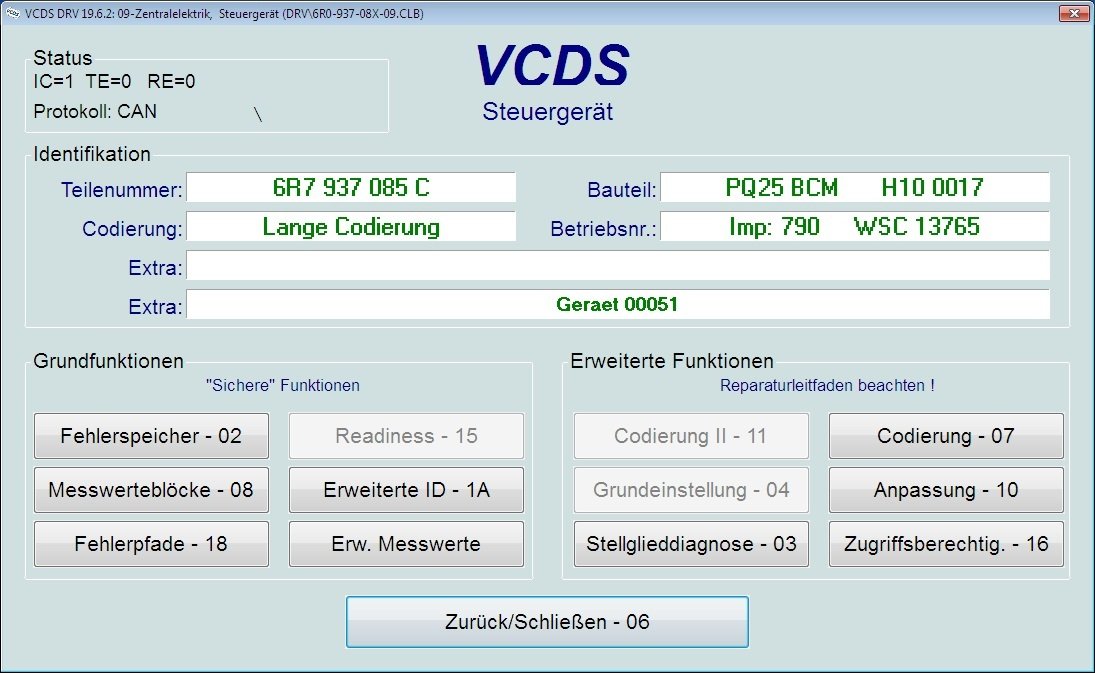
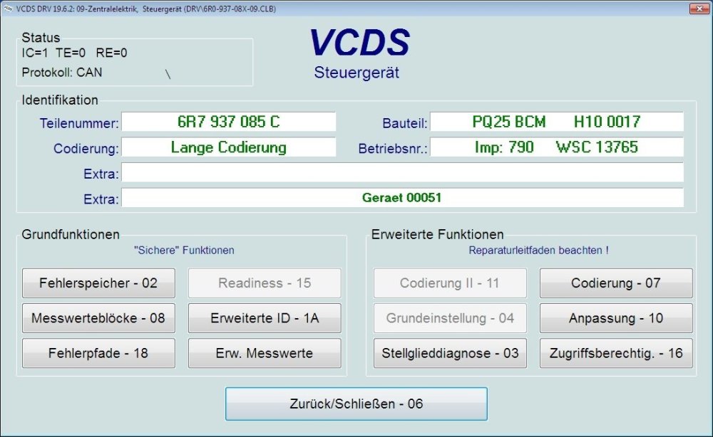
My test platform is working. 🙂 Wiring Diagram This wiring diagram works for me, but I'm not sure if it's correct! Cluster Pins to BCM 28 - Drive train CAN high – T32a 19 - Drive train CAN high - T73b 29 - Drive train CAN low – T32a 18 - Drive train CAN low - T73b OBD2 Pins to BCM 6 - CAN high 23 - Drive train CAN bus high (switched) - T73b 7 - CAN low 22 - Drive train CAN bus low (switched) - T73b 14 - K-Line 37 - Diagnosis wire K - T73b Power T15 (+12V - Ignition) Cluster Pin 31 BCM T73a Pin 44 T30 (+12V) Cluster Pin 32 BCM T73b Pin 39 OBD Pin 16 T31 (Ground) Cluster Pin 16 BCM T73b Pin 38 OBD Pin 4/5
-
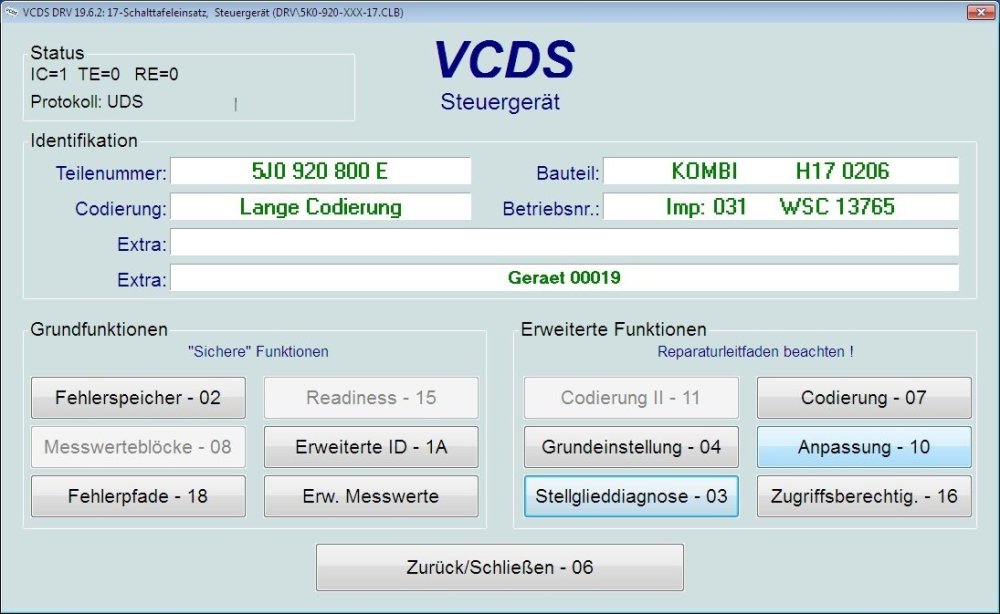
@Cairus Thx for reply. Do you have more informations about this resistor "hack"? I'd like to try it, just for fun. 😅 Yesterday I connected a BCM and was able to query its memory. Today I'll also integrate the cluster and try it out.
-
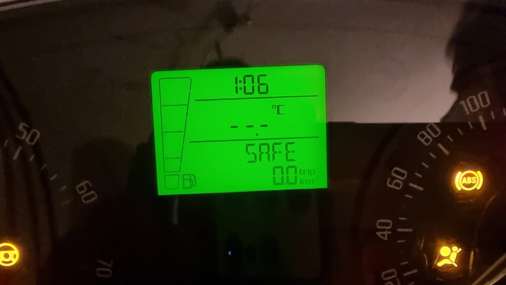
Found a Pinout and it works for PWR ON, but no Diag direct to Cluster possible with VCDS. ☹️ Cluster Pinout 32-pin connector -T32a- : 1 - Fuel gauge sender -G- 2 - Fuel gauge sender -G- 3 - not assigned 4 - not assigned 5 - not assigned 6 - not assigned 7 - Immobilizer reading coil -D2- 8 - Immobilizer reading coil -D2- 9 - Speed signal - Ouput 10 - Speedometer sender -G22- 11 - Oil level and oil temperature sender -G266- 12 - not assigned 13 - Rear fog light warning light -K13- 14 - Main beam warning light -K1- 15 - not assigned 16 - Terminal 31 - Input 17 - Windscreen washer fluid level sender -G33- 18 - Coolant shortage indicator sender -G32- 19 - Ambient temperature sensor -G17- 20 - Terminal 31 (sender mass) - Output 21 - Multi-function display -J119- - Function selection switch -E91- 22 - Multi-function display -J119- - Function selection switch -E91- 23 - Multi-function display -J119- - Reset button -E92- 24 - not assigned 25 - Handbrake warning switch -F9- 26 - Brake fluid level warning contact -F34- 27 - Oil pressure switch -F1- 28 - Drive train CAN bus, high 29 - Drive train CAN bus, low 30 - Fog light warning light -K17- 31 - Terminal 15 - Input 32 - Terminal 30 - Input
-
Hello everyone 👋 Is it possible to test a facelift cluster on bench? If yes, does anyone have a wiring diagram and is a BCM additional required? Regards
-
@Wino Many thanks for your help! It worked perfect...
-
@Wino Many thanks for your help!!! Tested it yesterday and it worked fine. Do you have more information on how I can connect to an instrument cluster? I know connections to power up the cluster, but I don't know which cables are needed for a data connection.
-
@Wino Thx for reply Some days passed now and no answer. I looked @hutchysrs50profile and see that he was last online 3 months ago.
-
Hi there I know it's an older thread, but I didn't find anything like this on my search. Does anyone still have some information about this Fabia cluster on desk project (wiring diagram)?