Bugrat
Finding my way
-
Joined
-
Last visited
-
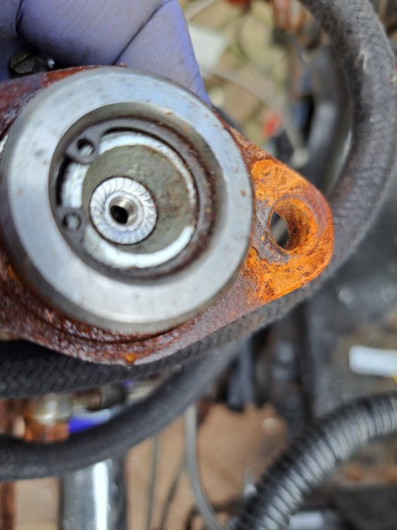
Went out last night, came up to a junction & could see I could pull straight out, so didn't change down just pulled out & floored all 50HP, the engine spun up & the clutch slipped, no worries I thought it just needs a clutch. Bit can I find one? Can I buggery, not even the suppliers in Czech Rep seem to have them, anybody with any ideas, the QH part appears to be QKT243AF but I'll take any make. The adjuster is all the way in, but there is still no play so is it properly foobared?
-
That is bizarre as I checked when you last posted them & couldn't find any, maybe the AI fairy's put them there when my back was turned, little barstools that they are.
-
Thank you for that I'm still struggling to get a rebuild kit and a suitable air filter
-
I 'think' I have, or rather I have used this logic, I know that the way it was plumbed was that one set of front pistons & the rear were on the same circuit, then the second pair of front pistons on the second circuit. A standard MC pushes the first piston directly from the pushrod, then uses a spring to push the second piston, but has a failsafe that if the first circuit fails the second circuit gets pushed by the pushrod so that is how I have plumbed them in. This all seems to have worked as it should but we will see once we get to MOT time. Thank You Nigel, it's always good to discuss as that fires things into the brain to think about. Hopefully this will assist somebody in the future, I hate to see a question asked, potential solutions offered & then no final confirmation of whether it worked or not. Alan.
-
Okay so spent some more time today going over the brakes, re-bled them again for good measure, did get a tiny bit of air out but nothing to write home about. Then wondered if it could be the rear drums that were not adjusting up giving the long pedal, so took the drums off & put a jubilee clip around the cylinders to prevent the pistons moving, this did not improve the pedal. Slackened the jubilee clip of the OSR & whilst pressing the pedal watched the cylinderit only started to move for the last 25% of the push. I then looked at the Servo to M/C connection, I measured how much of the pushrod was sticking out of the servo, it was about 13mm. I then measured how deep the point of contact would be & that was roughly 23mm which meant the pushrod had to move 10mm before the piston actually starts to move. As a temporary measure I placed a spacer in the bottom of the M/C to take up the slack, it was a bit too much, but then a plate between the servo & M/C got it just about right. This gives me a solid pedal at the start of the press, I then found that the OSR handbrake cable was corroded so that had to be resolved. All this was caused by the difference between a genuine OEM unit which are no longer available & units which are sold as direct replacements from 3rd parties which are not a direct replacement.
-
It actually does, now whether it needs it is another matter, I suspect not, I seem to remember it was overbraked with it (18 years ago), the intention was to get it back on the road with it fitted & then decide whether I should remove it or not. I've just rebuilt the front calipers, the rear cylinders look new, I actually suspect it's the auto adjusters on the rear that are not auto adjusting correctly & allowing the cylinders to be pulled back all the way in. They have a setup I've never seen before, a bar going across with 2 little rollers which grip with a spring. I've just found on https://www.skopart24.com/en-gb/shop/Bremse-c35177861?offset=30&limit=30 that you can buy both the adjusting arm (damn out of stock) & rollers for not a lot (not check carriage yet) so I may buy them just to put my mind at rest they are not causing the issue.
-
Don't do Faecesbook, it's the devil incarnate only surpassed by AI, I know I sound like a Luddite, but Faecesbook, tictok et al are a lot that is wrong with the world today & humans will regret their inventions. However thank you for the suggestion, I set them up last night with one set of fronts & the rears on the port nearest the servo & the other set of fronts on the other port. They do work but I have a lot of travel, I thought I had bled all the air out, but it feels like there is still a lot in there.
-
The next issue is the brakes, I believe they are off a 136, (not 100%) but they are 4 pots on the front & drums on the rear, the servo & M/C have been turned 90 degrees so they are now flat & not stuck up in the air. They are currently plumbed so that the 1 set of the fronts & the rears are connected together, then the other fronts are on the other outlet. Is this correct & from the servo which should be which. In the Haynes manual even in the Supplement it mentions 4 pots but shows a 2 pot system. Thanks
-
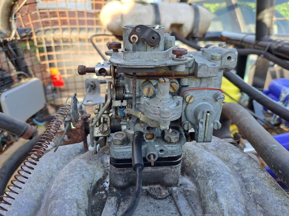
This is the carb if somebody recognises it
-
Well I can't believe I started this post 19 years ago & here I am back again, I sold the car a year after the initial post, then I bought it back last year. In the intervening years somebosy has fitted a Weber card, but I'm having difficulty in identifying it. It has 24-21 stamped on it, what I suspect is a serial number W450309 but I can't find a model number. It does run, but I can't get it to idle properly, I was hoping to get a repair kit for it, as some of the rubber sealing rings have perished & there's a diaphram which looks a bit suspect. Alan.
-
Ah, well. maybe it's not the original then, Sorry I don't know. It was built from a 1989 136 Rapid I was lead to believe, I also understood it was a one donor car, so I presumed that header header/expansion tank came from the original car. I will get an image later today
-
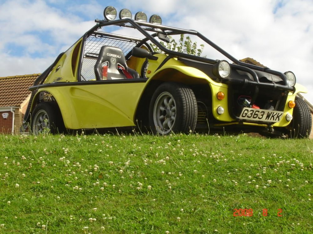
It's a plastic tank with a metal pressure cap. As to Bugrat you're on the right lines(is) with a dune buggy, this is what it looked like in 2007 when I last owned it
-
Yeah, it's the header/expansion tank, radiators are easy as they can still be obtained for not too much money, I've bought a new cap which for the moment appears to have resolved the problem, but we'll see when I eventually get it on the road.
-
Does anyone make a new one or have a good old one, or even a suitable replacement?
-
Thank you unfortunately all of those relate to a Alternator/Regulator, not an Alternator with a separate Regulator,