Dabber2024
Finding my way
-
Joined
-
Last visited
Everything posted by Dabber2024
-
Well here I am again and its time to pick this problem back up. So the gripping tale continues, as of last march I had put switched power to my radio to reduce the battery drain with the intention to perform further diagnostic with the arrival of a logging clamp meter, this is a bluetooth enabled DC volt clampmeter which allows me to measure current flow in a wire over a period of time in a table and graph. Given the previous information I gleaned regarding the water leaks from the rear washer jet causing a short in the rear wiper motor I was planning to clamp the power leads going into the wiper motor and see if there was a spike when the motor kept trying to "park" the wiper blade (as per stuff ive read on tinternet). Naturally the clampmeter has arrived and ive still not got to grips with it lols. I have had a quick go using it on the rear wiper motor leads but i need to get in and have proper go. So the reason for this update. Mavis (our fabia) suddenly decided to stop responding to the key fob this week, i changed the battery and that didnt fix it, i then noticed that the little red light on the key fob was working anyway so clearly its not the fob, or at least the fob is good for power anyway. The spare fob also failed to operate the locks. It has been raining heavily in our area this last week after the prolonged hot weather I should add. We have therefore been locking and unlocking the car with the key, when doing so the only lock that opens is the drivers door lock, in order that we can open the boot i have to press the centre console mounted lock/unlock button and then go and open the boot as normal. When i press this lock/unlock button on the centre console (below the radio area of the dash) it makes an interesting pair of noises, normally it makes an unlock noise followed by the different and sort of "heavier" clunk of the deadlocks coming off, now it makes the initial sort of whining click noise and then repeats itself as if its started an operation and then reversed itself by performing the same operation. Its hard to describe but it now makes two noises that sound the same rather than the correct two noises that are distinctly different. Additionally at no point has the central locking activated itself to unlock any of the other doors, we have to use the internal handles to unlock them. As you can imagine I have by now read many many articles on door locking and electrical gremlins, including @Breezy_Pete interesting article on reflowing the solder joints in the door lock where his earth joints were cracked. This article also ed in with something I read about the shared earth of the door lock unit contributing to the door button for disabling the internal alarms malfunction. I have also read many articles on wires in the door cable grommets being cracket or broken and the issues these cause which can be varied. As mention previously I also am pretty sure my rear wiper has been leaking over my rear wiper motor (theres a lot of rusty deposits and rusty number plate lights apertures) and causing the failiure to park problem which could be triggering a battery drain. However the one thing I have not read so far in this saga is the most recent trick Mavis has pulled. Basically having locked up with the key earlier today I came down around dusk to go for a drive in Mavis, only to find that the drivers front headlight and drivers rear running light were turned on !!! Note i say drivers side ONLY. The car was still locked and I dont thing the little red light on the door was flashing to indicate the alarm is on was blinking but couldn't swear to that. At which point my wife clicked the key fob opne button that hasnt worked for 5 days now, and the bloody car opened up !!! All the doors !!! I have never seen this one sided malfunction occur before in my life, it is possible in my Talbot Talisman for this to occur because the right and left side of the vehicles lights go through different fuses and the main operating switch must send power to both fuses. Are Fabias wired up so that the drivers side lights go through a different fuse than the passenger side ??? And even if they do how on earth is it possible that power can flow to the lights when the car is locked and the key not even in the ignition ??? Somehow the car has turned its own lights on and unless the ECUor Body Control Module actually perform part of the power switching task between the manual switch and the light bulbs then I cannot see how this is possible ............UNLESS somehow power has been flowing from a short to the lightbulbs Thoughts anyone ?? Dabber
-
This was the video ! Excellent knowledge that man. New alarm has arrived need to get round to fitting it. Update on TOPDON carpal readings...retested today after clearing all codes previously. The alarm missing code is back...and also the passenger door inaudible signal ! so.. hypothesis time... The old owner had a dodgy door close signal This set the alarm off intermittently They decided to remove the alarm The door locking signal fault is still there The ECU brain is searching for the Lin wire thats commuinicating with the (missing) alarm The ECU brain is now confused and somehow keeping the radio turned on in the background When I clean and refit the alarm siren I expect to get it going off intermittently but I wont delve into the inaudible door signal fault till I have seen if the radio parasitic drain goes away .. Watch this space
-
Im not sure Pete, quite possibly , do you have a link please ? I would like to get some more knowledge as re-flowing the soldered joints is something I can do easily enough. Ta Dabber
-
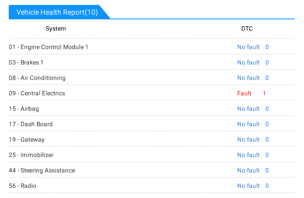
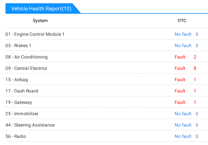
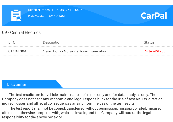
Hi Alasdair, thanks for the input, i had not considered the possible shared power supply to the siren. As it stands my siren was missing when I looked the other day, pretty annoying. The new one off Aliexpress is on its way !. So todays update is only to show what happened when I ran a scan using the TOPDON CARPAL. This is an obd2 scan tool with additional car specific libraries of info you can download and use, they have good reviews . I ran the first scan below and there were several error codes which my old school code reader would not have been able to see. I have attached the detail of the codes as 1st scan details pdf and theres lots of implausible signal codes and an airbag code and then theres the 01134:004Alarm horn - No signal/communication Active/Static. Its the only code that was written in Red, the rest of them had text to tell me they were ok to ignore. So I performed a DTC code clear and re-ran the scan and the only one left was the Horn code. So, Im hoping that the old codes are indicators of some dodgy alarm related triggers from the door locks or something and the airbag code might be something from someone else doing work on the car. When the new siren arrives I will get it plugged in and try it. There are 3 wires from the alarm siren earth, power and a communication wire which is either Lin Line or K line (not sure), I should be able to trace the signal wire back to the combined Voltage control Module/Body Control Unit (i hope). The possibility that the control wire is keeping everything awake is well documented either by ways suggested by Alasdair or otherwise. Dabber 1st scan.pdf
-
Hi Pete, agreed on the microswitch. I cant find the post I read about the car door locking unit which pointed me towards poor soldering in the unit. What with the interior sensor disable button not lighting orange when pressed and the iffy pattern of flashes of the little red indicator light on the top of the door card somethings amiss. Went to look round the breakers yard for a fabia alarm siren , none present, checked several golfs as well and passats , could not even find the alarm sirens on them ! i was looking under the front panel below the windscreen and also the drivers wheelarch , most odd, i must be lokoing in the wrong place. Anyhow I guess i will have to actually buy one from Aliexpress.
-
apologies
-
@JR RS Judging by the dash display the door close and open switch is working, thats not to say it doesnt need cleaning at the least though, which I will do. Octavias might work without an alarm siren but I would like to have a working car alarm on my fabia and from the many other fabia posts and sites I have studied the dodgy alarm battery or link does cause a battery drain, possibly through the 3rd control wire in the connector plug. At present my time only allows for brief periods of work so no taking of the door to pieces yet. I will check the door bellows next all round the car. I am working on installing VCDS lite just need a microsoft PC first and apparently a cable (usb to OBD2) not all cables work though so need to get one that reads the K line it seems. @Breezy_Pete Thanks for the part number, I will be looking at sourcing one asap, there are options from Ali express i believe but to be honest my local scrap yard will be the first place to go I think to get OEM, then perform a battery replacement on the part if required. I am hoping to find a 1K0951605F on a newly scrapped recent model if it is now the VW go to part number, maybe its on the new octavias ? who knows. Fix alarm horn first Investigate bellows Check for parasetic draw again Arrange day to take door to pieces and look at the microswitch possible open the controller module to check the solder connections as there is an interesting post around the earth causing trouble regarding the interior door alarm sensor disable button. From the research done so far the interior sensor deactivation button should be lit red then turn orange when pressed to indicate it is in action. I might visit the skoda garage to see another fabia in action. Dabber
-
Hi there, ive just been searching for "skoda fabia part number nomenclature" I spent 3/4 years working in the engineering department at Bentley as the go to man for parts and tools etc, the naming structure (nomenclature) of the VW system was adopted when they took over the company just after I started. The link below will get you started. https://www.darksidedevelopments.co.uk/Blog/vw-part-numbers-explained/ There is also a full skoda parts list which you have to pay to access, you can run a parts list by VIN number apparently from this : http://www.partslink24.com/ I have just discovered (thank you @Breezy_Pete ) that the horn to fit my fabia was part 1K8951605B, which has been superseded by 1K0951605F. Which is interesting as the first three digits 1K8 indicate: 1K = Volkswagen Scirocco (2009 - 2014) 8 = Coupe from https://vagupdate.com/blog/vag-part-number-structure This has been superseded by the 1K0 1K = Still VW Scirocco 0 = Not specific to LHD or RHD models Things to consider here, and this comes from my years working within engineering at Bentley This is an alarm siren, it has no reason to be handed i would say. Also VW group will not allow engineers to create new part numbers on a whim, there is a strict part release process (3 stages in TEVON system? ) which ensures no new parts are designed when one exists already across the VW group. Its costs many thousands of pounds to revise a BOM, Drawing, Stock holding, part number etc, so they wont do it if possible. Providing the designation 1k as a VW Scirocco is correct from those other sites I am guessing that at design phase of the MK1 fabia the designers were given a packaging space within which they could use the VW Scirocco siren and told to get it fitted. Given there was no requirement to make a handed part (which in practice generally means a model specific part like a wing for example) they did exactly that upto at least Rev B on the MK2 possible later. Then along came the need to supersede the original part number to 1K0 which I am thinking means the part has been moved to another area of the BOM not specific to LHD or RHD models and will be used going forward as the standard VW alarm siren until the physical shape or function is forced to change by outside design factors. good luck Dabber
-
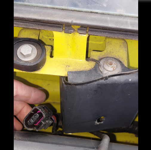
@Breezy_Pete @J.R. Comments noted and will check the alarm fuse. The radio does indeed work, and I am looking at getting a vagcom connector and downloading VBCDS-lite Update: Following from my previous entries I am pursuing the course of least resistance and have now re-routed the 12V power to the radio from its original fuse (50) and have taken a power lead from fuse 1 (micro fuse) bus rail, which is switched. So now at least I dont have to keep whipping the fuse in and out. Next I took a look under the front scuttle for the alarm siren horn.....guess what....no alarm siren present, the wire and connector plug was lying loose in the scuttle but the horn has been removed, looks like someone mangled the bracket slightly as well. See attached. I stated on https://www.briskoda.net/forums/topic/525881-alarm-interior-sensor-shut-off-switch/ this post that my drivers door indicator light was also showing an error somewhere in the central locking ref the flashing sequence of the little red light at the top of the drivers door card. So my thoughts are now running to there being a central locking issue, triggering the alarm all the time, so someones removed the alarm, and now my battery drains and the central locking is not always working right. So 1st this means I need to buy the alarm siren, which means the right part number , my best guess so far is 1K0 951 605 C for the part number based on looking for internet sales for fabias from 2011. I could do with this confirming however if anyone happens to know the correct part number for a skoda alarm siren ? Thanks Dabber
-
@cbeds7 Appreciate this is an old thread however I wanted to share a bit of info I just gleaned: from this link https://www.b-auto.net/skoda_fabia-1/central_locking_system-747.html God bless em. Warning light in the driver's door After locking the vehicle, the warning light flashes for around 2 seconds in quick succession, afterwards it begins to flash evenly at longer intervals. If the vehicle is locked and the safe securing system » page 46 is not operating, the warning light in the driver door flashes for about 2 seconds fast, goes out and starts to flash evenly at longer intervals after about 30 seconds. If the indicator light first flashes fast for about 2 seconds, then lights up for about 30 seconds continuously and then flashes slowly, there is a fault in the central locking system or in the interior monitor and in the towing protection » page 50. Seek help from a specialist garage. I know this doesnt answer your question but bare with: Basically my mk2 1.6 tdi has got a red light like yours in the drivers door to turn off the interior sensors, mine lights up red as I open the door, I press the button, it goes out but comes back on again, after a short time it goes out permanently. I then move about in the car and the alarm doesnt trigger. Before placing any faith in the button I have to first repair the horn unit in mine because it doesnt make any noise, the indicators do flash however which is whats telling me that the interior sensors are indeed being turned off..HOWEVER the section of text in red above is whats happening to the little red light at the top of the drivers door card so clearly I have a central locking problem which is maybe why my Interior Sensor Off button is showing symptoms like yours of being lit red when logic would suggest it shouldnt be untill pressed ? thoughts ? Oh ive also read on this forum that the central locking, little interior sensor button, alarm horn etc are all wired together and sharing earths inside the door .....
-
Well J.R., i need to find a reason as to why the battery drains 3.5 V over 4 days , theres nothing ghostly about that. It may be that the fault does not lie in the CANbus but as per the table below from right at the start the values for power draw are above normal (quiescent ? ) Situation 2 & 3 No. Power consumer Fuse rating (A) Fuses in our box With engine running (mV) Converted using fuse chart to mA Engine off, bonnet and door latches locked and car locked, after 1 hour (mV) Converted using fuse chart to mA 22 Operating controls for the heating, control unit for air conditioning system, parking aid, mobile phone, instrument cluster, steering angle sender, ESP, vehicle voltage control unit multifunction steering wheel 7.5 mini fuse 7.5 mini fuse 4.6 mV 424 mA 0.5 46 mA 24 Central control unit of the vehicle 5 mini fuse 5 mini fuse 3.9 mV 220 mA 2.6 mV 146 mA 49 Turn signal lights, brake lights 15 big fuse 15 big fuse 0.1 mV 21 mA 0.1 mV 21 mA 50 Radio 10 big fuse 10 big fuse 4 mV 519 mA 3.9 mV 506 mA Some more study on you tube diagnoses the curious equal voltage values on can hi and low of 2.51 V in my test 8, they were static values on the meter with no fluctuation, as described at 15:00:00 in this video https://youtu.be/JicbzR3Juh0?feature=shared this might indicate can hi and low are shorted together, so Mr Diagnostek says to perform a resistance test between can hi and low at the OBD, in his video he gets a 0.2 Ohm resistance instead of 60 ish Ohm and hes suggesting that means the can bus wires are shorted together rather than to ground as he also had equal static voltage values. In my readings my OBD can hi and low resistance check gave me a good 60 ish ohm reading BUT my resistance check at the RADIO plug gave me a 0.1 Ohm when really it should have been 60 ish ohm (according to the other video https://youtu.be/fZMNzKpCGfc?feature=shared here.) I shall research alarm horn issue and also remove the J519 module as I might be able to at least split the two CANbus systems and determine something more. Ultimately I have to fix this car otherwise my wife will get anxious driving it and I am not having that, perhaps this level of diagnostics is a bit much for an amateur but the battle is far from over - cue bugles and the sound of the Light Brigade
-
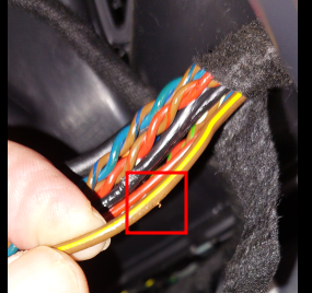
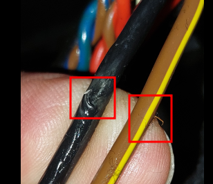
Small update on the radio parasetic drain. Based on my belief that there is a short to ground on the radio canbus somewhere i took a look at the radio wires, they were fitted badly and part of the loom where it disappears to the right of the radio was slightly damaged. One of the black radio aerial wires was showing bare silver wire and also the earth wire (brown/yellow) that terminates in pin 12 ( Voltage supply, negative, terminal 31) So i taped these up in the vain hope this might be the cause of a short. It didnt seem to be, i refitted the stereo and after 30 mins tested the current drain again and the radios still pulling voltage. Ref Pete i felt along the loom and can feel the bulge where the radio wires join the main loom, can see it of course 😞 still good to know where it is. Before I get to removing the dash I am wondering if it is some other module thats giving the whole system the yips as it were and Ive come across videos of similar battery drains being caused by the alarm horn. Interestingly on the times that I have been testing the car I have had the door and bonnet locks tricked waiting for the CANbus to go to sleep and when I opened the door to get in the indicators all started to flash, BUT no horn sound ! so Im now wondering if the alarm horn is up to no good, thanks to some advice I can see the Horn for the alarm is not on either the CAN line however hmmmmm. My mate has a mate in Northwich who is a auto tech and we shall take the car to him one saturday to see if he has a tool that can run a diagnostic and show the topology map of the CAN bus lines, if he has all the gear then that night rule out the radio, though the short to ground is still there, im going to check that tomorrow when I switch batteries I think ,make sure I wasnt seeing things. Dabber
-
Cant thank you enough Pete, im going to look at that now. For anyone interested heres a link to a site with lots of workshop manuals and diagrams on every VW group car out there ! https://www.vag-hub.com/fabia/fabia-mk2/
-
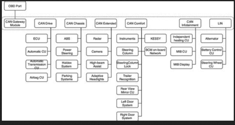
Any thoughts on the above post would be welcome, tomorrow I shall start stripping back the can bus wires from the radio as I believe the ground short is causing other modules like the Voltage control unit to misfire and stay awake, in turn this is keeping the radio on which enhances the battery drain. I still really need a diagram of the canbus network and the points at which I can split the loom to test the separate parts. I found this which is maybe for an octavia. ive also just found this: on another source.
-
Hello all Back to it today and starting from the top with a fresh battery. Firstly i need to answer @Breezy_Pete I tricked the car locks and left the car for 30 mins or so and took readings across the fuses as you suggest. fuse 24 was giving a reading of 3.5 mV, this is the central control unit fuse. fuse 22 was also giving a voltage of 0.5 mV this is the voltage control unit fuse amongst other things. Fuse 50 (radio) was no longer giving a reading, the radio was not fitted for this test. The battery was still depleting but at a much slower rate as previously mentioned in my posts. So it seems the radio is not the only source of the drain. I next went through the tests from the video but jigged the order, first i left the battery negative cable off, then i attached the battery neg cable but left the ignition key out of the barrel, then I did the tests again with the ignition on. The results are tabulated below. The first thing i noticed was that the 66.6 Ohm reading between can hi and lo at the obd2 port was not repeated at the radio multiplug which I have a feeling it should have been The next thing I noticed was the constant voltage of 2.51 V on both can hi and lo at the obd2 port with the battery connected, my understanding was that can hi should have read 2.58 ish V with Can lo reading 2.4 ish V. Im not sure what to make of all this other than, the main spine of the canbus is intact, the radio spur from the canbus gave a reading of O.L which is wrong. So my thinking is the canbus leads from the radio are broken prior to joining the loom. I also think there is a voltage short present somewhere, maybe at the same point. Test number Test purpose Notes Result Further questions Test 1 Establish battery voltage Fresh fully charged 12.9 V Test 2 Ignition off battery not connected Is the CAN network asleep. At the OBD2 port. Check voltage between AN hi and CAN low pins 6 and 14 on the latest CAN design (post a2008 ? ).Reading should be 0 V if network is asleep 0 V No battery connected..no power anywhere Test 3 Ignition off battery not connected Resistance check of the network at the OBD2 port and the terminating resistors. Test between CAN hi and CAN low There are two resistors built into the two modules at the two ends of the network, they are 120 Ohms each. Measure resistance between pins CAN hi and CAN low pins 6 and 14 should be 60 Ohms 66.6 Ohms So the main spine of the CANbus is in one piece If you get a GOOD 60 Omh reading It could still be a module has a break in one of its CAN wires, providing the module is Not a gateway module OR it doesn’t contain a terminating resistor Resistance check of the network at the radio multiplug can hi and lo. Test between CAN hi and CAN low Measure resistance between pins 9 CAN hi and 10 CAN low, 0.1 Ohms Given the main spine is reading 66.5 Ohms I was expecting to read that at the radio plug, am I correct in this presumption ? From the video notes they say, providing the radio is NOT a gateway module or has no terminating resistor then this test when performed at the OBD2 port would indicate a possible break in the Radio CAN wire or other module Test 4 Ignition off battery not connected Short to ground at the OBD2 port– You cant test resistance with current flowing Set to Continuity and check between Chassis Ground (pin 4) and CAN hi and low. If ANY CONTINUITY IS DISPLAYED THEN THERE IS A SHORT TO EARTH ON the circuit somewhere. If YOU GET 60 Ohms on both CAN hi and CAN low then thats good Pin 6 CAN Hi 14.41 kOhms Pin 14 CAN low 14.41 kOhms Short to ground at the Radio multiplug CAN hi lo Set to Continuity and check between pin 9 & earth and pin 10 & earth, Pin 12 used as earth Pin 9 CAN Hi 3.64 MOhms Pin 10 CAN low 5.8 MOhms Value kept climbing on the scale , no continuity beep Test 5 ignition off, battery connected Check voltage at the OBD2 port Set to DC Volts and check between Chassis Ground (pin 4) and Pin 16 power, should get the battery voltage reading 12.9 V Test 6 ignition off, battery connected Is the CAN network asleep. At the OBD2 port. Check voltage between AN hi and CAN low pins 6 and 14 on the latest CAN design (post a2008 ? ).Reading should be 0 V if network is asleep 1 mV How can the meter measure voltage BETWEEN the two can hi and lo pins ? They both carry voltage normally when awake and to measure the voltage the electricity has to flow to earth doesn’t it ? Is the CAN network asleep At the radio mujltiplug. Check voltage between pin 9 can hi and pin 10 can low 3.5 to 4.9 V Value was fluctuating Test 7 ignition off, battery connected Check voltage at the OBD2 port Set to DC Volts and check between Chassis Ground (pin 4) and Pin 16 power, should get the battery voltage reading 12.88 V Test 8 ignition off, battery connected Short to voltage at the OBD2 port Set to DC Volts and check between Chassis Ground (pin 4) and CAN hi and low. No voltage should be displayed if the BUS is asleep. If you get voltage then theres a short to voltage somewhere Pin 6 CAN Hi 2.51 V Pin 14 CAN low 2.51 V Static value no fluctuation. Short to voltage at radio multiplug can hi lo Set to DC Volts and check between CAN hi pin 9 & earth and CAN low pin 10 & earth. Pin 9 CAN Hi 0.59 V to 0.8 V Pin 10 CAN low 4.3 V to 4.9 V Value was fluctuating Short to ground at the OBD2 port– You cant test resistance with current flowing but tried it anyway Set to Continuity and check between Chassis Ground (pin 4) and CAN hi and low. If ANY CONTINUITY IS DISPLAYED THEN THERE IS A SHORT TO EARTH ON the circuit somewhere. If YOU GET 60 Ohms on both CAN hi and CAN low then thats good Pin 6 CAN Hi O.L no buzzer sound Pin 14 CAN low O.L no buzzer sound Short to ground at the Radio multiplug CAN hi lo Set to Continuity and check between pin 9 & earth and pin 10 & earth, Pin 12 used as earth Pin 9 CAN Hi O.L no buzzer sound Pin 10 CAN low O.L no buzzer sound Test 9 ignition ON, battery connected Is the CAN network asleep. At the OBD2 port. Check voltage between AN hi and CAN low pins 6 and 14 on the latest CAN design (post a2008 ? ).Reading should be 0 V if network is asleep 0.9 mV How can the meter measure voltage BETWEEN the two can hi and lo pins ? They both carry voltage normally when awake and to measure the voltage the electricity has to flow to earth doesn’t it ? In this test obviously there is no battery connected but later Is the CAN network asleep At the radio mujltiplug. Check voltage between pin 9 can hi and pin 10 can low 3.49 V to 3.52 V Value was fluctuating Test 10 ignition ON, battery connected Check voltage at the OBD2 port Set to DC Volts and check between Chassis Ground (pin 4) and Pin 16 power, should get the battery voltage reading 12.53 V Short to voltage at the OBD2 port Set to DC Volts and check between Chassis Ground (pin 4) and CAN hi and low. No voltage should be displayed if the BUS is asleep. If you get voltage then theres a short to voltage somewhere Pin 6 CAN Hi 2.53 V Pin 14 CAN low 2.53 V Static value no fluctuation. Short to voltage at radio multiplug can hi lo Set to DC Volts and check between CAN hi pin 9 & earth and CAN low pin 10 & earth. Pin 12 used as earth Pin 9 CAN Hi 0.71 V to 0.75 V Pin 10 CAN low 4.27 V to 4.23 V Value was fluctuating
-
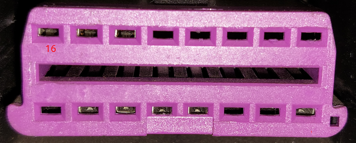
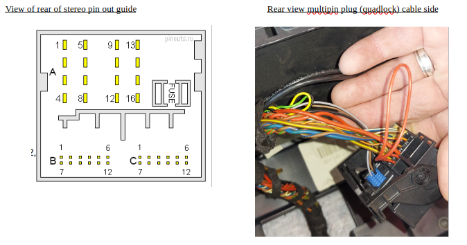
SKODA Fabia, Diesel 1.6 Registered Sept 2011.Elegance. Swing Radio Checking on my quadlock multiplug A connector indicates that my Rear and Front LH and RH speakers have been wired in reverse (my fabia was built in Spain BTW) See table below, Pin 1 & 4 for example in my car the Red Green wire on pin 4 should really be on pin 1 according to Haynes Manual. I have colour coded the speakers in the table so you can see which ones have been wired in reverse. I have not tried using the Fade left and right of the stereo to confirm this as the only DEFINITE way to know which wire goes to which speaker is to check at the door hinge or at the speaker. It may be that I can run a test current down the speaker wires individually and see if the speaker makes a noise, this would be better than ripping the doors open to get to the speakers (sigh). Terminal pin BLOCK A My wiring colours What Haynes Manual says Correct or wrong ? 1 Rear right loudspeaker, positive Blue/White RD/GN WRONG 2 Front right loudspeaker, positive BLUE RD WRONG 3 Front left loudspeaker, positive RED BU WRONG 4 Rear left loudspeaker, positive Red/Green BU/WH WRONG 5 Rear right loudspeaker, negative Brown/White BN/GN WRONG 6 Front right loudspeaker, negative Brown/Blue BN/RD WRONG 7 Front left loudspeaker, negative Brown/Red BN/BU WRONG 8 Rear left loudspeaker, negative Brown/Green BR/WH WRONG 9 CAN bus, high green/orange OG/GN CORRECT 10 CAN bus, low brown/orange OG/BN CORRECT 11 Display voltage supply, positive, optional only on the Low radio version 12 Voltage supply, negative, terminal 31 Brown/Yellow BN/YE CORRECT 13 Display HS CAN bus low, optional only on the Low radio version, not for Midline 14 Display HS CAN bus high, optional only on the Low radio version, not for Midline 15 Voltage supply, positive, terminal 30 2 off Red wires RD CORRECT 16 Anti-theft coding control signal, SAFE, positive Single Red RD CORRECT FAbia RAdio plug wiring pdf version.pdf
-
Right, quick addition. Went to the car yesterday and the battery was down to 9.9 V, which was slightly more declined than I was expecting but as the cars still draining power not a surprise. The car was opened with the fob, then the door locks tricked and the bonnet lock tricked.The radio has been removed for 2 days or so now. I repeated Test 2 is the canbus asleep ? - Result was no current between Pin 6 & Pin 14. I had assumed that by opening the car doors I would have triggered the CANbus awake , but it seems not. Would be interested in views on what actions are needed to wake up the CANbus ? I then performed Test 6.. Short to ground and short to voltage - the results were the same as before, no continuity but a voltage reading of 2.52 V. So the voltage line of the CAN is shorting to the other line of the CAN (im not sure im correct in suggesting only one line of the CANbus net carries voltage as I believe the system works on voltage differential between the lines ?) Regardless its still a short. I suspected a short in the radio or the radio Quadlock connector, so I then performed. Test 4.. Remove the suspect equipment (radio) and do a resistance check from the CANbus wires that connect to that module..I studied my Block A multiplug and worked out the pins to check from the front of the BLACK plug block, used my homemade crimp attachments to check resistance between the wires - the reading was OL (NO RESISTANCE). which is BAD. The testing video I watched tells me that I should have been getting the 66.4 Ohms I had at the OBD2 connector if the Loom is OK . So it seems there is a break in the CANbus Loom somewhere. This is consistent with the indication in test 4 of the short to voltage. So my radio unit is probably OK. Terminal pin BLOCK A My wiring colours What haynes says Correct or wrong ? 9 CAN bus, high green/orange OG/GN CORRECT 10 CAN bus, low brown/orange OG/BN CORRECT At this point I performed a continuity check on the pins within the plug block, 9 and 10, from the front of the pin to the back of the pin, they are good with continuity. So now I need to work out what units make up the CAN bus and where on earth the CANbus wiring runs in the car 😞 I need a map of the CANbus as it sits within the car - if such a thing exists , i cant find one yet. I replaced the battery with a fully charged one and closed up for the night. Today I shall go back down and start the car etc to try to wake the CANbus up, im not sure why I don't get voltage showing the can being awake when I would have thought it should be ? After that I shall trick the locks again and wait half an hour and do as Pete suggests and measure the voltage drops as I didn't want to do that with a low battery in place. If anyone can supply a CANbus map that would be very helpful. Dabber
-
Thank you Pete. I shall sketch out your info on a diagram for future people to peruse. I will do as you suggest on fuse 50. But first I will run the tests now the cars sat with the radio out overnight as thats almost the same.
-
I left the battery connected last night and removed fuse 50 thinking I would start doing some testing via the OBD2 port. HAts off to you tube and this video @Ecutestinglimited This is all greek to me to be honest so my first hurdle was to understand the layout of the OBD2 port, simple yeah ? No The thing is my fabia is a 61 plate so SHOULD be the one post using the K line type of "CAN" however to check I wanted to make sure i didnt stick the probes of the meter into the wrong holes and electrecute myself or the car. So lots of places should the standard obd port layout pins 1 to 16 and what they do , however I couldnt find a specific diagram of the fabia one, not only that but every picture I viewed did not make it BLINDINGLY CLEAR if the view of the pins was from the front (drivers seat) or the back of the OBD port. The image shown is as viewed from the drivers seat, and the standard multimeter probes do not fit into the OBD2 port slots....so I gave up in frustration The next day it wasnt so cold and grim and I decided to have another go by cutting off one of the legs of a crimp connector (below) and creating a homemade probe adapter, worked fantastically. At this point I should say that I had unlocked the car using the fob and the battery had been connected all night with fuse 50 for the radio removed. I commenced with the tests in the video by checking the battery, 12.4 V which had dropped from the last night slightly (nothing like the normal drain I should add) I decided that pin 16 - permanent 12 volt was the top row far left, and by testing with my multimeter from this pin to an earth point on the car body . You will see that there is a metal glint in the top row 3 left hand slots and 5 slots in the bottom row have a metal glint. So without knowing I could have assumed pin 1 was pin 16 given I was unsure of the pin layout to start with...which I duly did and of course pin 1 carried 12 V !!! At this point I decided to turn the ignition key off, something which I was unclear about initially despite my youtube cruising. When I retested with the ignition off I found that the top left slot as viewed above carried 12.4 V Can anyone confirm that pin 16 is as I describe when viewed from the drivers seat ? Onto the tests: Test 1 - battery check was a pass. 12.4 V Test 2 is the canbus asleep ? - I took a reading between the (assumed) pins 6 and 14 and got 0 V , so my canbus was asleep, though I question this as my clamp meter (on battery negative wire) was giving readings which suggested otherwise. Test 3 resistance check between pin 6 and 14, there was no open circuit and the reading was 66.4 Ohms, slightly higher than the 60 Ohms in the video but not lower than 60 ohmsor bang on 120 ohms which would have indicated other issues (see the video), rather I am taking my slightly high reading to show resistance caused by poor connections. Test 5 - not required Test 6..(yes its out of turn I know) Short to ground and short to voltage - checking for continuity between pin 4 (chassis ground-i hope) and pin 6 and then pin 4 and pin 14 gave me a reading of 0 and no signal from the continuity buzzer, so all good there. Then checking for voltage between pin 4 and pins 6 and then 14 gave me a voltage reading of 2.52 V, which apparently shows there is a "short to voltage" according to the video I watched that is were the voltage line of the CAN is shorting to the other line of the CAN. So I am thinking that short could be at the plug on the radio or (worse) somewhere else in the entire CANbus network and that this short is keeping the radio powered up, that said apparently according to test 2 my CANbus net is asleep. Test 4.. Remove the suspect equipment (radio) and do a resistance check from the CANbus wires that connect to that module..and once again here I am struggling, several of the wires that go into the terminal plug on the back of the stereo are twisted together, which is how the CAN hi and low cables were described to be. Also I need to test from the front of this plug as I dont want to try ramming things into the back. Tomorrow I shall go back to it, locate the right pins for can hi and low in the radio plug and do a resistance check backwards to the CANbus network. Hopefully I will get the 66.4 Ohm reading or indeed a 60 Ohm reading and I will know the wiring is sound and it must therefore be the radio itself. I am not sure however if by removing the radio I will cause the rest of the CANbus to keep "hunting" for the radio module ? I have read somewhere ab out people having to de-registger their radios with the car "brain" and re-register new ones when they do swap outs etc. Really I need to know for sure what the slot numbers are as viewed from the front of the OBD2 port, and what they do, if I am right then my OBD2 port has connectors for the ISO9141 L line at pin15 and the ISO9141 K line at pin 7 , which I did not think it would have as its post 2010 and should be ISO 15765-4 spec. I should be able to marry up the cable colours from the circuit diagram in the haynes manual to the ones I can see in the back of the radio plug and work out the CAN hi lo wires. So thats it for today. Im sick to the back teeth of clever cars, my reliant rebel does not have these issues Any thoughts on the above would be helpful please, I know is a long read and I have some more tests from the video to do but Rome was not built in a day. I would like to fit a bluetooth streaming radio into the car, but I dont want anything that will cause CANbus issues (which I believe the Amundsen will do ) so Im thinkng the bluetooth swing radio which is from the rapid will be good for me (i believe) anyone know if this is a straightforward mither free and future proof swap please ? thanks for any advice peeps Dabber


-
Unfortunately VCDS Vag Com is extremely expensive otherwise I would consider it. I have looked through a few posts on VCDS and its not clear whether VCDS is capable of determining the sequence/order of whats happening within the network. As I understand it (so far) the CANbus network is a series of wires connecting various Electric control modules back to the Engine Control Unit, E.g. wiper motor has two wires running to the ECU. I have also read that the various modules only take data from the CANbus network they dont send data, now this I dont believe as otherwise how would the car know the boot was open (for example) or if the rear wiper was parked successfully (another classic battery drain issue apparently) My primitive OBD scanner shows no codes (as you would expect) and I cant afford a more expensive VCDS VAg Com reader ... Im wondering if theres a secret screen on the swing radio that will tell me more info or somewhere in the system ? ~Hopefully someone has had this battery drain issue caused by their stereo and knows the issue better than I do. Or how to establish if just changing the radio would fix the problems, but then how do i register a new radio into the CANbus so the car knows it exists ?
-
Thank you J.R, for your thoughts. I have read elsewhere that the ignition key housing sends a signal to the Controller Area Network ( CAN ) once the key has been removed and that the CAN is always waiting for this signal to totally turn off the radio. Have you heard this ? additionally other people have mentioned that the CANbus network can be kept awake by other units and then this can lead to the CANbus not shutting the radio down, I dont know how much to believe this though as I doubt that just by the CANbus system being active would cause a signal to go to the radio.. Does my car have a gateway controller ? I have heard of this sort of thing but I thought the factory fitted radio linked directly to the CAN network with no gateway linked in between. I have attached a circuit diagram where I have highlighted where the power comes from the battery and into the back of the radio, also the power forks off to the Navigation System Interface (except my car does not have navigation), the navigation system interface is also controlled from the CAN by two wires which are connected to the Onboard Supply Control Unit (my car has this as its post 03/10) . So what and where is this Gateway I wonder ? Would the local dealer be able to scan the radio or the CANbus to see more info and thus diagnose whats making the CANbus stay awake ? or why its telling the radio to stay awake ? Thanks in advance, Im clutching at straws a bit as I have no idea how to interrogate the CANbus system itself. Circuit diagram radio highlighted areas.pdf
-
Hi all Right, ive started a new topic as my first topic was titled "1.6 TDI FABIA 2011 PLATE: fusebox layout and missing fuses rear wiper not working" and no longer describes the situation I am facing. old thread : https://www.briskoda.net/forums/topic/528866-16-tdi-fabia-2011-plate-fusebox-layout-and-missing-fuses-rear-wiper-not-working/#comment-5910143I solved the fusebox layout by reading a lot and consulting the haynes and as for the rear wiper not working, the actual fuse was in the wrong slot, maybe deliberately by the garage as I have now discovered the battery has a parasetic draw. null I had problems with the UNI T clamp meter I had bought, subsequent testing against a brand new alternative clamp meter confirmed my UNI T was not calibrated correctly and giving me nonsense readings. I also was using an old school normal multimeter to take readings but I suspect the amp scale in it is not refined enough to help me (the mV scale seems fine though). So , new thread, more educated approach. lets go. From my last thread you will see that I have purchased a mk2 1.6 TDI fabia called Mavis, and the seller mentioned vaguely that the battery was flat at some point, I bought it anyway and sure enough after 3 days on the drive the battery was flat. I have since charged the battery to full and drop tested it on starting, the process for which is outlined in my last thread but simply involves watching the voltage drop across the battery terminals when cranking the engine, the battery was cranking above 10 V so its as good as can be expected. I also brought in two bigger batteries I have as slave batteries, both of these charge fine and also got drop tested and passed. I am considering purchasing a brand new battery from somewhere and taking it back when it also drains out though i kind of think this is a pointless think to do. I have finally got a grip of my measuring skills and managed to establish i have a battery draw, I decided to pull fuse 50 (radio ) as this was the one that seemed to be causing problems and I then put a fully charged Numax battery in the car to measure how long in days the voltage would take to drop: Date/Time volts 13/01/2025 16:50 12.80 14/01/2025 20:31 12.26 15/01/2025 08:58 12.08 16/01/2025 16:50 12.02 17/01/2025 16:50 11.95 18/01/2025 16:50 11.88 as you can see the voltage dropped over 6 days but not by enough to cause me issues, indeed the car started fine. I then took the Numax battery off and inserted a fully charged (13.43) Starline battery, putting the fuse 10 back into place and I took readings to see how the voltage dropped for the next few days. Date/Time Geotec meter fall in value V 18/01/2025 16:50 13.43 v 19/01/2025 14:06 12.34 v 1.09 v 20/01/2025 16:50 12 v 0.34 v 21/01/2025 09:06 9.6 v 2.4 v as you can see the fuse 50 for the radio has made the battery drain a lot quicker. Using the Starline battery on the 18th I took readings for the drain when the battery was fully charged. i have a clamp meter (new one) on the negative battery lead and it gave me a reading of 0.850 A but when placed in line on the earth side seemed to give 0.450 A either way the car was drawing power. I then measured the voltage drop across the fuses in 3 different situations: 1..At standing, battery connected key in ignition no engine running (mV) - this is where I simply opened the car and installed the battery and took the readings. bonnet and door latches are tricked to seem closed by latching them with a screwdriver 2..With engine running (mV) - took the amp clamp off and fired up the car, again latches closed. 3..Engine off, bonnet and door latches locked and car locked, after 1 hour (mV) - I tricked all the locks and left the car for at least an hour to go to sleep before i took readings. SItuation 1: No. Power consumer Fuse rating (A) Fuses in our box At standing, battery connected key in ignition no engine running (mV) Converted using fuse chart to mA 22 Operating controls for the heating, control unit for air conditioning system, parking aid, mobile phone, instrument cluster, steering angle sender, ESP, vehicle voltage control unit multifunction steering wheel 7.5 mini fuse 7.5 mini fuse 0.5 mV 46 mA 24 Central control unit of the vehicle 5 mini fuse 5 mini fuse 2.7 mV 152 mA 49 Turn signal lights, brake lights 15 big fuse 15 big fuse 0.1 mV 21 mA 50 Radio 10 big fuse 10 big fuse 3.8 mV 494 mA Situation 2 & 3 No. Power consumer Fuse rating (A) Fuses in our box With engine running (mV) Converted using fuse chart to mA Engine off, bonnet and door latches locked and car locked, after 1 hour (mV) Converted using fuse chart to mA 22 Operating controls for the heating, control unit for air conditioning system, parking aid, mobile phone, instrument cluster, steering angle sender, ESP, vehicle voltage control unit multifunction steering wheel 7.5 mini fuse 7.5 mini fuse 4.6 mV 424 mA 0.5 46 mA 24 Central control unit of the vehicle 5 mini fuse 5 mini fuse 3.9 mV 220 mA 2.6 mV 146 mA 49 Turn signal lights, brake lights 15 big fuse 15 big fuse 0.1 mV 21 mA 0.1 mV 21 mA 50 Radio 10 big fuse 10 big fuse 4 mV 519 mA 3.9 mV 506 mA Situation 3 shows the voltage drops re appear an hour after the engines been off and are the same fuses as in situation 1. So its clear from the battery depletion records that fuse 50 ( radio) is causing the biggest drain..and its clear ii its over half an amp on a 63 amph battery so its going to last 31 hours say. Next step im going to take the radio out and see what happens. Theres lots of post about Swing radios and parasitic draw, i can see the CAN is linked to the Power controller module and ive heared stuff about cutting wires etc, im just not sure if the radio staying on and drawing this power is a symptom of the CAN link not letting the radio turn off ( ignition barrel switch ?) or is the radio itself is knackered and its the radio not letting the CAN rest... tail wagging the dog or vice versa ? Its obvious to me that the last owners garage have been messing in the fuse box and may have suspected the rear wiper, hence the misplaced fuse. Thoughts from others welcome .... please
-
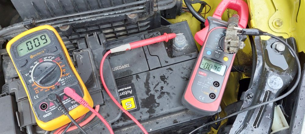
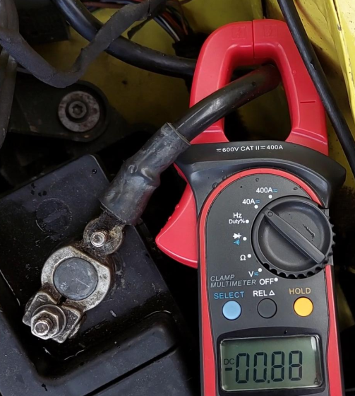
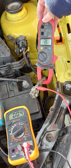
OK, im back and happy new year to all. Ive decided to invest in a clamp meter, a UNI-T UT203. These meters provide a DC amps current reading so hopefully i can check the parasitic draw and get me past my problems of reading the scale of my other meter. Having left the car over christmas and new year I returned to it today with another as yet untried battery, my intention being to test the alternator diodes and output first before looking at the drain. Firstly i opened the car using the key (as the car had no battery in to do the unlock), then i closed all the door deadlocks and the bonnet lock manually to simulate a locked car. No battery installed as of yet. So: test 1:Battery not connected, negative lead on the alternator B+ post (B+post cable removed and isolated), positive lead on the alternator casing gave a reading 0.541v on the diode setting which is within the 500 to 800 range which all the you tube videos suggest a good set of diodes to be read, test 2: as above but reversed the leads, negative to casing and positive to B+ post of alternator, reading was OL on the screen which i believe means no reading possible and again is correct according to the you tube tutorials. test 3: Install battery and in doing so mount a voltmeter in series with the negative battery cable and the battery negative post and also mount the clampmeter to the negative battery cable. I did this because i wanted to see what the draw would be immediately upon installing the battery and also to see what my two meters compared to each other as. The clamp meter was set on the 40A DC autoranging feature and gave a reading of 00.76 with the battery negative lead running through the clamp, the other meter was connected to the end of the negative lead and then to the negative pole to complete the circuit and gave a reading of 0.009 on the 2A range setting. The problem I have is that I am still unsure as to what unit these translate into, my guess is that the 00.76A reading is actually 7.6 milliamps, as upto this point I had not triggered any electrical drains by opening doors etc (door locks and bonnet were already tricked), Using this logic I am then deducing that the other multi meter set in series with cable and post was showing me 0.009 in the 2A range which actually means 9 milliamps ? I thats right then thats a good current drain to have as its less than 10 milliamps. Im sure reaing these machines is easy but I cannot understand why the machines dont simply display the correct unit and the number rather than leaving it open to my crap interpretation. Am I right in what i believe these machines to be telling me ? test 4: Voltage from alternator with engine running. Original battery voltage was 13.27 V after a full charge from its previous voltage of 12.97 V. Started the car and at tickover measured voltage with positive lead on the B+ post of the alternator and the negative lead on the casing of the alternator the reading was 14.52 V with the engine running, then moved the leads to the battery and got a reading of 14.53 V, so happy with that, my wife then put the radio and AC on and the lights and brought the engine to 2500 rpm and I read the output at the battery again at 14.48 V. So far then everything is as it should be (i think - please tell me otherwise anyone). Next my intention was to turn the car off and measure the current drain at the negative battery lead and watch it to see where it gets down to, again my issue here is I dont really know what the meter is telling me so some more assumptions to follow. Immediately after switching of the engine at 13:10:00 the clamp meter read 5.08 A on autoranging, drivers door being open and not tricked and the car starting to go through the engine off cycle of its electronics, this dropped to 01.10 A some 90 seconds later at 13:11:42 when i stopped the video. The next reading I took at 13:13 was down to 01.11 A , within another minute it was down to 00.89 A on the clampmeter. At this point i am guessing that this is a reading of 88 milliamps not 880 milliamps but again who would know as its not clear from the machines screen.Pic attached. Next at 13:28:00 I decided to break the circuit and put the multimeter inline with the negative lead whilst also running the clamp meter on the negative lead. Interestingly the readings dropped significantly to 00.26 A on the clampmeter and 0.004 on the multimeter on the 2A range setting. My guess is that this reading is 4millamps or 4 thousanths of an amp as its 3 decimal places on the multimeter, quite how this relates to the ampclamp reading of 00.26 is anyones guess.Pic attached. I am now going to guess that disconnecting the negative lead to insert the multimeter inline forced the car to shutdown briefly ? So I removed the inline multimeter and put the negative lead back on the battery with the clampmeter, and the clamp meter is reading 00.88 again. At this point the hailstones became to much to bare and I called it a day, leaving the healthy battery attached and the car all back together again, cold and dejected i sat down to type this saga. Tomorrow I will pop the bonnet and see what the battery is reading, hopefully its still at around 13V. I did start testing the fuses again using the multimeter as per various you tube tuturials but I could not find any where the current flowing did not reduce to 0 after a second, as Jock pointed out in previous replies there should not be a current flow across the fuse unless something is earthing that fuse and any switches between the fuse and the earth point are closed (on). If my diodes are good (which they seem to be) and the alternator is charging fine (which it is) and mone of the fuses have a massive current going through them when the engines off...then what else could it be ? Something thats not attached after one of the fuses in the fusebox, something thats on the fuses under the battery cover perhaps ... hmmmmm
-
Morning Jocko, well, so far so good , the car measured 0.008 on the 2mA scale and still had 12.21v. And turned over first time ! So....problem solved.... Thanks for the advice so far, im going to just leave it connected now and fire it up every day for a week and see how she schoons. Merry christmas Dabber
-
Hi Jocko, thanks for the explanation regarding the voltage, id forgotten the switch needing to be on as well. Ive been out this morning and good news (i think). I was able to open the car using the keyfob which was a good start, i then proceeded to measure the voltage of the slave battery which had been connected overnight (expecting it to be depleted) and it wasnt !, I got a reading of 12.89v (higher than last night !) I then put the meter between the negative terminal and the negative battery cable and got a reading of 0.008 on the 2mA range , so roughly the same as when i left it last night. So i then swapped out the slave battery with the old battery that came with the car, having charged it overnight, in situ this battery gave a reading of 13.35v across the terminals which reduced to 12.98v after I connected the neg lead to the terminal and did a drop test by turning the car over. The results of the drop test were the battery dropped to 12.55v when i put the ignition on and then fell to 10.44v when i fired the starter motor. Thats leading me to believe the battery is sound. However I shall leave it connected till tomorrow now and check everything again. I went on to measure the current drain between the negative terminal and the negative lead with the old battery in situ and got the same reading of 0.008 on the 2mA range. Depending on what happens tomorrow should prove out if the battery is kaput for sure, if it is then its off to the scrapyard with it and I shall invest in a new one. If it isnt kaput then Im wondering what exactly i have done to reduce the current drain from the first reading of 180.7 on the (presumably ) sub 2mA range ? Ive now found something on the internet identifying this mystery range as “1.5V mA” setting on a meter is used to measure the current at a 1.5V voltage level, typically for testing how much current a circuit or device draws at this voltage" I cant understand why this worked on my 12v battery however The only thing I have really done is to leave cable 2 detached overnight accidentally, other than that ive simply pulled and tested all the fuses ostensibly. Maybe the original battery was simply very dead initially, maybe the cable 2 needed taking off to allow something in a circuit somewhere to go to sleep ? I guess we will see how the old battery fairs tomorrow morning, I might just leave it connected and check morning and evening to log the battery voltage over a week or so. Bloody electrics.