

Joel SHOEMARK
-
Posts
170 -
Joined
-
Last visited
Content Type
Profiles
Forums
Gallery
Shop
Events
Downloads
Posts posted by Joel SHOEMARK
-
-
I received quick replies from Damian and pretty happy with the service. His prices are awesome and even with shipping it's cheaper for me to buy from him and pay the freight to Australia.
Priced, invoiced and payed with in 2 hours from a forum referral.
Happy Days.
-
 1
1
-
-
Hi,
£460.83 plus £135.00.
Damian @ DPM Performance
Just sent you 2 emails, mate. The first one was incomplete, thanks to my 5 year old son.
 .
.Prices are sweet and I'd like to order them.
Happy Days
-
1
-
-
Hey Damian,
Will you send to Australia. Can you give me a price with freight?
Happy Days.
-
Absolutely agree with you. Our Yeti just had to renew rear discs and pads - 37000miles and 5 years old. Never had this on any other car. Car always garaged and discs dried off by braking after washing car. Previous Fabia had a problem with rear brakes sticking! Just what rubbish are these discs made of now???
I think this is pretty common with most cars these days. My last car was a Subaru WRX. I replaced the rotors with every set of brake pads. I think it's something with the brake pads compounds containing more metal. Rotors have always been consumables but they are just getting consumed quicker these days.
I also don't think stabilty control helps these days. Unrelated vehilce I know but to demonstrate the effects of stabilty control. Newwe Land Rovers have a thing called trailer sway control. The idea is the stability control detects sway of the trailer and counteracts it with brakes. The system works so well though the driver often cant detect sway. So when a trailer like a caravan is loaded wrong like too much weight to the front or rear the trailer would normally cause the vehilce to sway, sometimes uncontrolably. Just note some Land Rovers have air suspension that raise and lower to keep a standard ride height so you don't see vehicles sagged or raised in the rear from badly loaded trailer. The issue comes when the system has been working so hard to counter the sway of the trailer the brakes are worn out within 1000km.
Happy Days.
-
3
-
-
S on the way into a corner a D on the way out.
-
1
-
-
Cheers; I see what you mean.
Did you secure the cable outside the car (between the grommet and the 13 pin plug)?
And did you just plug it all in without disconnecting the battery?
I can't remember how I secured it. Everything came in the kit.
Yep, Just plugged it in. I did have the ignition and accesorys turned off.
You still need the vehicle prorgammed for the rear park sensors to turn off.
Happy Days
-
I hope you're still here Joel? I am planning to fit the same wiring to mine (following a towbar fitting debacle mentioned elsewhere) and your guide above is first class. The only bit I would like some more advice on is the routing from the module to the 13-pin plug at the towbar. I gather there is a grommet that needs to be removed on the underside of the car, and that the wiring kit comes with its own grommet? Then how does the cable run to the plug? Is it secured once outside the car? And do you think I could run this with the bumper still in place... you see I have the bar fitted now but no wiring. Oh, and did you disconnect the battery, or just plug it in live? It has been suggested that I attach the earth first, before the connector plugs...?
Hey mate,
If you look at photo 17, just before I start puting panels back in,, you can see the cable runs down to the grommet in the left hand side. The bracket that the 13 pin plug mounts on is a seperate peice. It actually allows the plug to swing down into place. It then swings up out of the way when the hitch is removed and the cover on. Without the bracket on the plug fit through the hole and there is another grommet that is part of the loom itself.
Happy Days.
-
x3 on S mode being pretty useless on the Diesel.
I use S coming into corners and then change to D at the Apex on the way out.
Happy Days.
-
Well. Over 2500km down and the lights are working OK with 100w halogen bulbs in them.
To ejstubbs. Yes I stuck with the transistor circuit. Mainly because I didn't want to get a CANBUS error. As far as I know all loads are monitored. As you say this circuit should be more than able to handle a couple of hundred milliamperes but if the system isn't expecting any load then it might generate an error and turn off that system. I can only confirm it doesn't see 2 milliamperes. As for wiring the relay direct, experiment at your own risk. I would at least recommend using a resistor in series to at least limit the current draw.
I say the light are only working OK as the HID kit I ordered didn't turn up before I left. This the first time I have run halogen driving lights in over 6 years and while they are good for halogen, they have nothing on HID.
Happy days.
-
This is them.
http://www.ebay.com.au/itm/like/300960171844?lpid=87
They do look so much better than the flat strap that is sold as light support strap. I think hella call theirs 2 point mount. It's just flat strapping with slotted holes. You get the light where you want it and do up the bolts in the slotted holes, holding the strap at the set length.
Happy Days
-
Cheers Joel.
That looks like my idea will be fine then, as I intend to use a couple of these:
http://www.memfast.co.uk/shop/Vprod2.asp?cat=2257001824
through the plastic.
I think the vibration is from the softness of the plastic. I have no doubt of the strength to hold the lights. It's just a little flexable and allows the plate to move. I have also added a couple of stays of the top of the lights that completely stop that forward/back movement of the top of the lights.
I'm also into RC Helicopters so I crossed the hobbies a little and use some heavy duty (RC heavy duty) ball joints from the light to the car. The ball joints are connected by about 3mm threaded rod with a carbon fibre tube. The carbon fibre tube just hides the thread and looks cool..
Happy Days.
-
Looks neat.
I presume you didn't use the bar thing then?
That looks like you have mounted them on a alloy plate with the top bent at right angles, using the number plate mounting screws. Is that correct? It is similar to the thoughts I've had, as I have about 8mtrs of 2" angle alloy at home from an old frame around a flue.
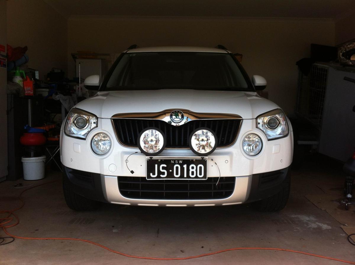
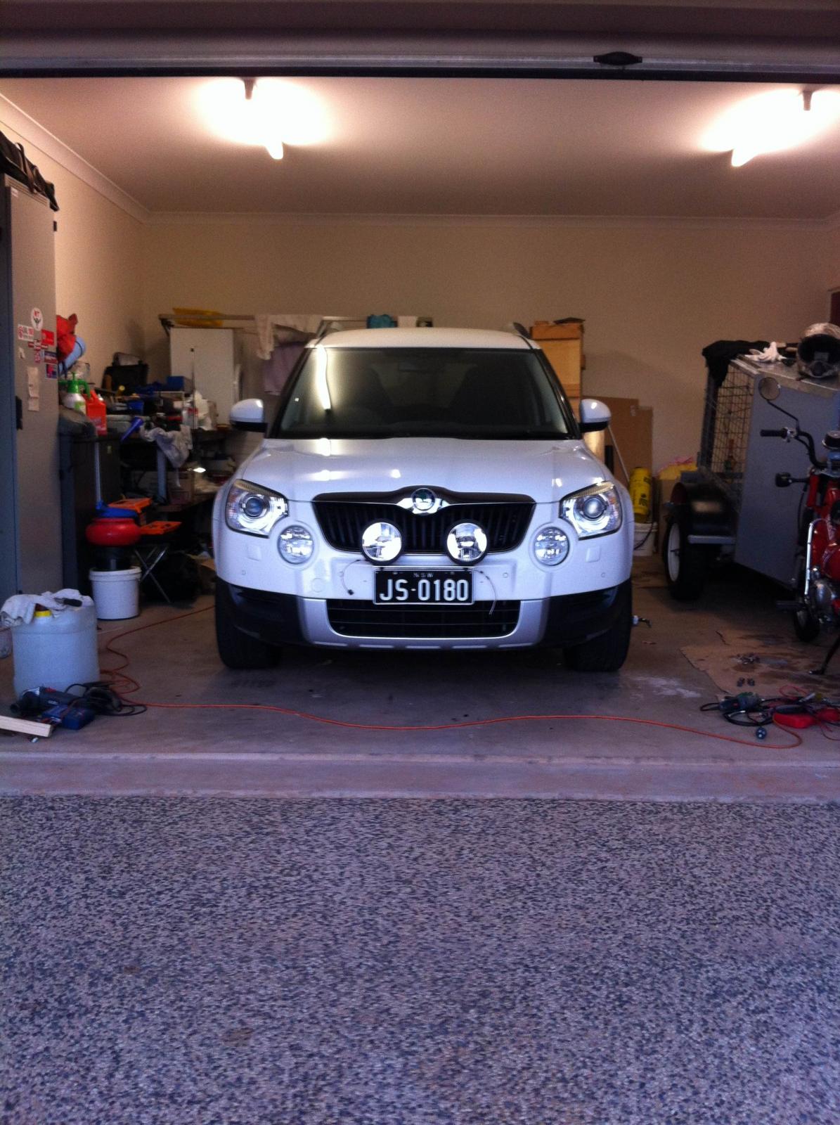
Yeh mate, Thats pretty much what the bar thing is. It's just a peice of alloy angle thats pollished up. I has to cut the tube peice of the front because my lights are very low and wouldnt fit. It was only welded on the bottom side so my cutting is not visible unless someone gets lower than the lights.
As for mounting. I had the whole bumper off. Its so easy when you have the workshop manual. The plate had holes for 4 x M8 bolts but the silly thing was the lower 2 were only half way down the plate which is full number plate height. I went against my better judgement and just used the provided holes, only to find it was not rigid enough to stop the lights vibrating so I had to add 2 more at the bottom. I'll post pics but just imagine 3 x M8 bolts on either side, spaced out from the bumper to match the curve.
Dont worry about whats behind the bumber. It's just foam. I want to put all the pics together with instructions and information but here's a sneak preview.
-
Well this has to go down in history as the longest driving light install ever.
I have enough pics for others that want to try their own install but I'm leaving for a 2 week trip tomorrow, 10,000km to drive. I'll get them uploaded when I get back.
I have to say I'm pretty bloody happy with the result. These are all wired up but I'm waiting on a HID kit. If it doesn't arrive I'll put the 100w Halogens in.
-
Ok the last 2 days have been rubbish to say the least. Well until about mid day today anyway.
I have done a bucket load of searching, posted questions on several forums and sent a few Private Messages to people who had posted pictures of Skodas with driving lights. I was hoping that other Skodas might just use the same colour code with the head light wiring. Still no idea what wire was the high beam wire so I could use it to activate the relay.
All the wiring is sealed so I cant just test from the back of the plug. If I unplug connector, the Contorl Unit detects a break in the system, throws a code and turns off the light so I cont test from the end of the unpluged connector.
I managed to find the relay inside the head light and check the wires on the back. Power was all over the place and never anymore than 2.5v.
I was pulling my hair out and starting to think it wasn't going to be possible. A mate had suggested that I run a kick switch to the floor and operate the driving lights seperatly but that would annoy me to no end.
So late last night I found a site that had a downloadabe copy of the workshop manual and sold the key to operate it for 9.99 pound. I down loaded it over night and it turned out to be the best money I have ever spent on the Yeti.
I spent a couple of hours studying the circuit diagrams and by mid morning I was convinced that it couldn't be done. Turns out the Bi-Xenons have there own Control Unit. It monitors individual wheel speeds, steering angle, rear axle heigh to name a few. Turns out its a very cleaver unit. It receives Data from the main ECU and power then does it's own thing so there is no power wire as such going to the unit to open the shutter. It has it's own power and opens the shutter when it's told to via CANBUS data.
Then I considered that some people sell change over headlights from Halogens to Bi-Xenons. I checked the circuit diagrams for NON Bi-Xenons and found there is a wire from the power control unit that supplies power for high beam. Low and Behold it still workes even though everthing else is settup for Bi-Xenons.
So I now have a high beam power wire to activate my relay for the driving lights. It's Yellow with a grey line on the left side head light. I beleive ut's differnt on the right.
Happy Days.
-
1
-
-
I know, which is why I was trying to work out which contact each of your wires goes to.
Some relays don't have the contacts in quite the same order.
One side of each the coil and the switch are joined together and go to positive. So lets say 30 and 86. The other side of the switch (87) goes the the auxiliary driving lights. That leaves 85. 85 is the other side of the coil. Now if 86 is the positive side then 85 has to be negative. If you work through the pictures you'll see this is the leg that most of the components are built on. The transistor basically becomes a switch for this leg.
Sent from my iPhone using Tapatalk
Happy days
-
A quick google. 85 and 86 are either side of the coil. 30 and 87 are either side of the switch. Powering the coil generates a magnetic field which pulls the switch on.
Happy days.
Sent from my iPhone using Tapatalk
Happy days
-
Joel,
could you link your wires and colours to the numbered contacts on the relay, please?
Yep. No worries. I'm away from the office at the moment but when I get back, I'll get straight onto it. I think it's 8? and 8? Are the 2 coil wires and 3? and 3? are the 2 switched wires. Neither are polarity dependent normally but this circuit means they need to be.
Happy days.
Sent from my iPhone using Tapatalk
Happy days
-
So the yellow wire on the left is a postive wire one side of the coil in the relay and the positive to the switch in the relay.
The 2nd yellow wire goes off to the driving lights.
The bigger of the 2 white wires goes to ground (Negative) and the smaller of the white wires goes to the wire that operates the shutter in my Bi-Xenon lights.
I am no expert by any means and while I know what a transistor does and I have only used one once before, this is how I beleive they work. They can be used as both an amplifier or a switch. I've only used them as a switch because you dont need to be too specific about the values, as long as it's close it will work.
A transistor has 3 legs, Base, Emitter and Collector. The one I have used in a NPN (Negative, Positive, Negative) transistor. So the collector leg goes to the negative side of the power source, the base need a positive feed from the switching source and the emitter leg goes to the negative of what ever you are switching. Now god and other smart people know what goes on inside them but in their normal state there is no connectivity between the emitter and the collector. When power is applied to the base leg, power flows from the base leg to the collector leg then something special happens inside them and what ever power is flowing between the base and collector, a bucket load more will flow between the emitter and the collect it called current gain or something. The measurement of "a bucket load" is specific to different models of transistors and thats why I have never used them as amplifiers but I thinks it something like 100 times the current between the base and collector will be allowed to flow between the emitter and collector.
I have my circuirt hooked up to a battery now and I'll leave it there until the morning just to make sure it's all good. I'd hate to get it all in and wired up and then have a resister fail or somwthing stupid.
Happy Days.
Happy Days
-
And the end result is this.
The relay on its own took 124 milliamp to close the switch. I tested it like this.
It fluctuated a little to 124.7 Milliamp but who's counting?
And with the circuit installed, I tested like this.
And it uses 2.06 Milliamp.
-
Righto, I'm at work now hard at it. Obviously.
Next solder in the diode across the transitor for the Coller to the Emmiter legs. Make sure the negative side of the transistor is on the Emmiter leg. With the flat side of the transistor facing toward you the Emmiter leg is on the left. This is just another bit of protection for surge from the coil. I know I have mentioned it twice and I have installed the diodes but as I said before I do not think they are needed at all. One good thing with instlling to diode across the transistor is it makes it structurally stronger.
Solder the diode like this.
Then cut the negative wire of the coil and solder the transistor in the cut section with the Emmiter leg toward the relay. Like this.
Then get a peice of large size heat shrink and seal it all up like this.
-
Ok. Now the Transistor, resisitor and next Diode.
Solder the resisitor to the middle (Base) leg of the Transistor and the put on some heat shrink. Make sure you push the heat shrink up all the way so it doesnt short when you start bending the legs around.
I have to get ready for work now. I'll post up some more once I get to work.
Happy Days.
-
Ok. 2 x Diodes 1N4001, 1 x 5.6K Resisitor and a 2N3904 Transisitor.
Grab a relay holder. Mine looks like this.
2 legs will be the switched legs, the other 2 will be the coil legs. Grab the coil legs and cut around them with a razor. Then pull he sheath back of a little to expose the wire. Like this
Get your Diode. Diodes are clever little things that allow power to flow one way but not the other. In this circuit they dont do anything while the power is flowing and working but once power is turned off they flow power in the opposite direction and short out the circuit. This short basicly burns of the residual power and prevents it surging back through the ECU or somethig silly like that. I doubt the head light circuit for the car would be that sensative but what the hell, they cost $0.30. Mine looks like this.
Take it and connect it to a batttery and a multimeter like this.
You find that you have power one way, turn it around and there will be no power.
Mark one side so you know which way is which. The diods should be marked with white on one end. When the white end is going to the negative, it should flow power.
Oh and put some heat shrink over it so it wont short on anything.
Now mark one leg of your relay holder so you know which side is negative and positive. I have marked positive. (a bit silly but I marked negative on the diode).
Now solder the diode to the exposed wires. Make sure that its in the direction that WILL NOT flow power. Like this.Then put on some heat shrink like this.
-
Good news guys.
It works. (Bench test at least)
I'm at work tonight so photos will have to wait until tomorrow.
My multi-meter has a blown fuse so I couldn't use it to test the current draw of the base lead on the Transistor and my watt meter I use for RC stuff only goes down to 0.1amp and it doesn't register.
If my calculations are right, it should be about 2 milliamp. I tested the relay and it takes about 150 milliamp so 2 milliamp is looking good and shouldn't be a problem with the CANBUS.
I'll post all the pictures (there's plenty) tomorrow and I'll bring it to work with me tomorrow and leave it on test for 8 hours just to make sure the resisitor doesn't get too hot or anything like that.
Happy Days.
-
I'm going to have a stab in the dark here.
I dont think you'll have to get it coded back. There was a fair amount of discussion why they are not just coded for tow wiring from the factory and then all you'd need to do is install the module when you fit the tow bar. The coding just means you need to go to the dealer to get the tow bar fitted.
Happy Days.
 .
.


Bilstein B6 dampers for Yeti
in archive
Posted
Mine arrived today. Very happy with quick shipping and very good price. 10 days from order to at my door in Perth Australia.
Now to fit them tomorrow.
Happy Days