


arpster
-
Posts
14 -
Joined
-
Last visited
Content Type
Profiles
Forums
Gallery
Shop
Events
Downloads
Posts posted by arpster
-
-
On 21/03/2024 at 08:36, Breezy_Pete said:
The first thing probably worth checking is the 12V permanent power to the thick red/yellow, and also the thinner red/violet feed going to the 20-way door module connector. If you measure relative to the thick brown earth wire on pin 20 of that connector, you'll be testing the earth continuity through the bellows too.
There does seem to be two motors within the lock module, a lock motor and a safelock motor. Not really sure what the normal sequence of operation is, but they share one common wire, the green/yellow at the lock connection. The lock motor has a blue wire also going to it, the safelock motor has a grey/yellow.
I assume that when locking and unlocking there is a 12V potential difference applied on these wires. So for one direction of lock movement the common, green/yellow would be at - say - 0V and the other two wires given 12V, probably one after the other? For the other direction, the common would be at 12V, the other two earthed.
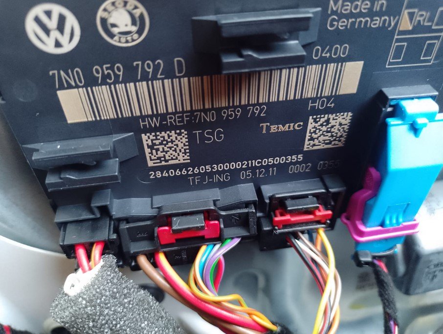
You can access the non-lock end of these wires at the 20-way connector that goes onto the door control module. Pin 11 is the common, green/yellow, 12 is the grey/yellow, 13 the blue.
You could just play around with applying voltage to these wires and hoping to unlock it.
BOOM!!!....😃.....followed the above instructions - and after numerous click and groans with the initial setup (12v to grey/yellow and to blue) ...I reversed the sequence as suggested - 12v to the common green/yellow and 0v to the other two and Boom! ...the door popped open...as did my jaw! ) .....was finally able to access the cursed door loom and sure enough - two small snapped wires ....heck of a job repairing them as only had about 40mm of wire to play with but just about had enough to extend / solder and heatshrink .......doors (front and rear) now locking/unlocking...windows working...adjustable mirror and mirror indicator all good 👍
To say I'm pleased is an understatement ....first posted about this in December and its been doing my nut in all winter - no-one appeared to have ever had the same problem - or if they had there was no record of it and any forums/ youtube videos / facebook groups despite months of searching.........
MOT due later this week so had resigned myself to automatic failure and hefty auto sparks bill .....last chance saloon - and it worked!Can't thank you enough Pete......absolute legend mate.....several virtual pints coming your way! 👊 🍻
Cheers! On 21/03/2024 at 08:36, Breezy_Pete said:
The first thing probably worth checking is the 12V permanent power to the thick red/yellow, and also the thinner red/violet feed going to the 20-way door module connector. If you measure relative to the thick brown earth wire on pin 20 of that connector, you'll be testing the earth continuity through the bellows too.
There does seem to be two motors within the lock module, a lock motor and a safelock motor. Not really sure what the normal sequence of operation is, but they share one common wire, the green/yellow at the lock connection. The lock motor has a blue wire also going to it, the safelock motor has a grey/yellow.
I assume that when locking and unlocking there is a 12V potential difference applied on these wires. So for one direction of lock movement the common, green/yellow would be at - say - 0V and the other two wires given 12V, probably one after the other? For the other direction, the common would be at 12V, the other two earthed.
You can access the non-lock end of these wires at the 20-way connector that goes onto the door control module. Pin 11 is the common, green/yellow, 12 is the grey/yellow, 13 the blue.
You could just play around with applying voltage to these wires and hoping to unlock it.
-
 3
3
-
 1
1
-
-
15 hours ago, Breezy_Pete said:
Do you mean at the lock module, or the door control module?
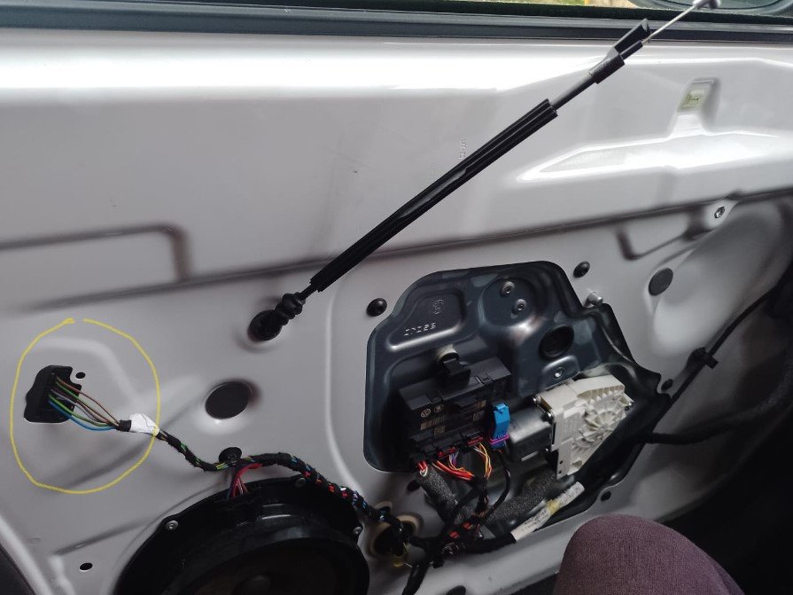
I was thinking you could unplug that 20-way at the door control module and feed 12 and 0V into the pin numbers mentioned above, by poking thin wires into the appropriate contacts of the loom connector? Could actually just link across from the contacts that the thick brown 0V and thick red/yellow 12V appear on.
Make any sense?
Yep (hopefully!)....unplug 20-way connector.....link thick brown to the common green/yellow......and thick red/yellow to the blue - and then the grey/yellow....- and then reverse that sequence if required......fingers crossed!
-
On 21/03/2024 at 08:36, Breezy_Pete said:
The first thing probably worth checking is the 12V permanent power to the thick red/yellow, and also the thinner red/violet feed going to the 20-way door module connector. If you measure relative to the thick brown earth wire on pin 20 of that connector, you'll be testing the earth continuity through the bellows too.
There does seem to be two motors within the lock module, a lock motor and a safelock motor. Not really sure what the normal sequence of operation is, but they share one common wire, the green/yellow at the lock connection. The lock motor has a blue wire also going to it, the safelock motor has a grey/yellow.
I assume that when locking and unlocking there is a 12V potential difference applied on these wires. So for one direction of lock movement the common, green/yellow would be at - say - 0V and the other two wires given 12V, probably one after the other? For the other direction, the common would be at 12V, the other two earthed.
You can access the non-lock end of these wires at the 20-way connector that goes onto the door control module. Pin 11 is the common, green/yellow, 12 is the grey/yellow, 13 the blue.
You could just play around with applying voltage to these wires and hoping to unlock it.
Preliminary test shows power to the thick red/yellow - and the thick brown earth also seems ok! ...surprised me as I assumed one/both of these would be damaged or broken in the door loom?.........the wires in the 20-way connector correspond with your description Pete - so that was reassuring! - only problem is how do I access the ends of them to test or apply voltage to them?......they are tucked up and under in the multiplug....am I missing something?.....apart from common sense! )
-
2 hours ago, Breezy_Pete said:
The first thing probably worth checking is the 12V permanent power to the thick red/yellow, and also the thinner red/violet feed going to the 20-way door module connector. If you measure relative to the thick brown earth wire on pin 20 of that connector, you'll be testing the earth continuity through the bellows too.
There does seem to be two motors within the lock module, a lock motor and a safelock motor. Not really sure what the normal sequence of operation is, but they share one common wire, the green/yellow at the lock connection. The lock motor has a blue wire also going to it, the safelock motor has a grey/yellow.
I assume that when locking and unlocking there is a 12V potential difference applied on these wires. So for one direction of lock movement the common, green/yellow would be at - say - 0V and the other two wires given 12V, probably one after the other? For the other direction, the common would be at 12V, the other two earthed.
You can access the non-lock end of these wires at the 20-way connector that goes onto the door control module. Pin 11 is the common, green/yellow, 12 is the grey/yellow, 13 the blue.
You could just play around with applying voltage to these wires and hoping to unlock it.
That's great Pete!...thanks very much - ...currently away in my camper for a couple of days, so will work through these steps when I get back ....at least I know where to start now! 😎 👍
-
53 minutes ago, Breezy_Pete said:
I will try to look at wiring info at some point this evening, not sure if there will be one or two motors within your lock module, but there ought to be a way of sticking 12V across a pair of now accessible wires to unlock the door.
Thanks! 👍
-
12 hours ago, Urrell said:
Have you checked the wiring in the rubber boot
Is it a left hand drive? I thought the mirror adjustment and alarm LED were only on the right hand side drivers door.
Cant get at the rubber boot mate.......door locked shut
right hand drive - i was referring to the passenger side controls on the drivers door
-
On 13/03/2024 at 15:38, Crasher said:
I have had it work for me a few times, how did it go?
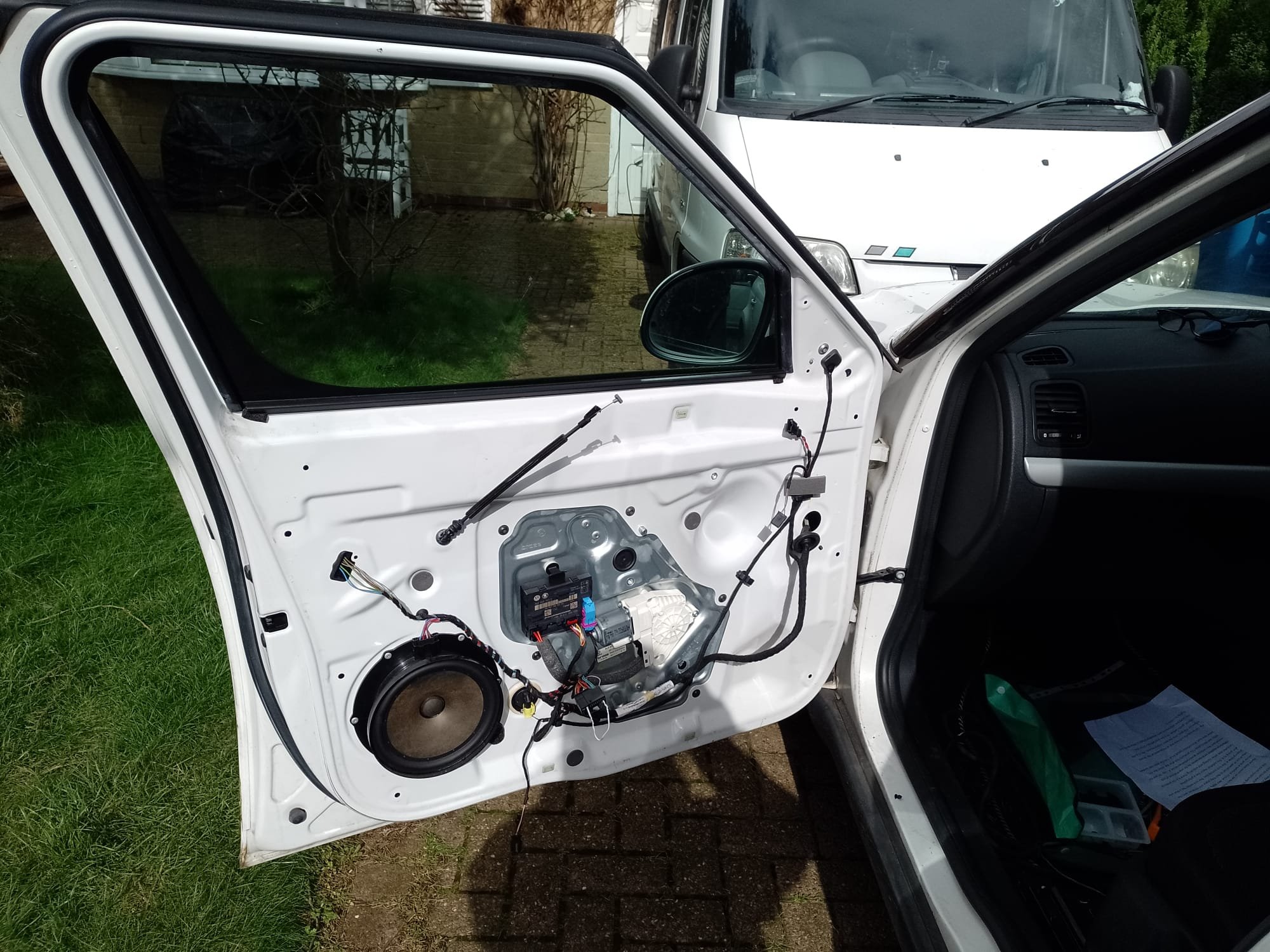
Unfortunately disconnecting the battery didn't work for me mate.............I have however managed to get the door card off (with the passenger set still in situ!)
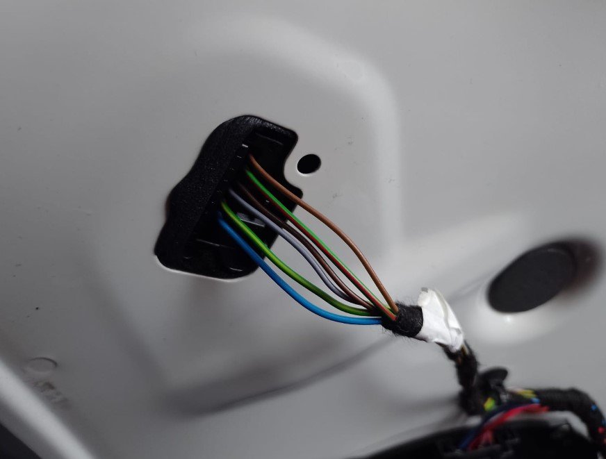
....again I have very little 12v electrical knowledge but would it be possible to run a temp wire directly from the battery just to get the door to unlock?......if so which wire should I be running it to?...(see pics)....is the thick red/yellow the main feed? (im assuming the main feed is broken)....
cheers
-
On 15/02/2024 at 13:13, Crasher said:
Disconnect the battery overnight.
not sure what that would do....but i'll try anything at the moment!! 🙂
-
On 15/02/2024 at 13:03, Breezy_Pete said:
There's not an emergency keyhole on passenger front door, hiding under a plastic cover, by any chance?
no such luck ! ......😟
-
On 14/02/2024 at 12:06, Breezy_Pete said:
I believe both of the front door modules are connected to the convenience CAN network, but each rear door is only LIN connected to its same-side front unit.
So for the whole passenger side to be affected I would think it will be front passenger side wiring problem, causing the front module to not be 'playing nicely' with the car as a whole. That in turn will mean the rear doesn't work due to the absence of LIN communication to tell it what it should do.
Having said all that, I haven't actually looked at the relevant circuits for the OP's car, but at that age/recency, I believe that is the general norm for VW group.
Thanks for the reply Pete....and I fear you may be right.....I followed J.R.s tip but there are no obvious signs of damage / cracks in the drivers door loom....and the fact that all the electrics on the N/S are out (doors / mirror adjustment / heated mirror / alarm led) ..makes me suspect it is indeed the loom on that side..........problem is of course, how the heck do i get at it?!..... ive no real idea how the locking electrics work but could a car locksmith maybe spring the door for me?......
cheers again for the help -
Thanks J.R. ........Id assumed the loop fracture would be on the passenger side as all electrics on the drivers side are ok....but will definitely investigate that!
-
HI all, My issue is that i cant access the passenger side door loom...the sub-zero cold snap lead to the electrics on that side playing up ...windows wouldn't come down, electric mirror wouldn't adjust and the doors (front and rear) wouldn't lock - seemed to right itself with the help of multiple opening/closing/locking - but now in limbo as the doors are permanently locked - no amount of fiddling with the fob / centre console release / central locking fuse etc makes any difference - doors are locked shut - so i cant actually get at the loom and im now in no mans land .....any suggestions would be very gratefully received,,,,,,
-
HI all, thanks for letting me join.....been perusing for years but this is my first post
- im having a similar n/s door problem - but find myself in a bit more of a pickle! .....My issue is that i cant access the passenger side door loom...the recent sub-zero cold snap lead to the electrics on that side playing up ...windows wouldn't come down, electric mirror wouldn't adjust and the doors (front and rear) wouldn't lock - seemed to right itself with the help of multiple opening/closing/locking - but now in limbo as the doors are permanently locked! - no amount of fiddling with the fob / centre console release / central locking fuse etc makes any difference - doors are locked shut - so i cant actually get at the loom and im now in no mans land! .....any suggestions would be very gratefully received,,,,,,
All N/S electrics down.....
in Skoda Yeti
Posted
Thanks mate.....hopefully this'll help others with Yeti door issues! 👊