russ17
Finding my way
-
Joined
-
Last visited
Everything posted by russ17
-
Hi Amateurtje, I followed your guide and everything worked out fine. I purchased an SKF Aftermarket hub (SKF VKBA3644) direct from SKF via Amazon for £45.50 (in Aug 2021) https://www.amazon.co.uk/SKF-VKBA-3644-Wheel-bearing/dp/B00AJU0I58/ref=cm_cr_arp_d_product_top?ie=UTF8 Bearing was an easy fit on my 2007 Octavia 2 1.9TDi Combi. I found I was able to remove the disc WITHOUT removing the caliper bracket, which saved the difficulty in removing the triple square bolts, so I just needed to remove the caliper bolts, which are 13mm Socket and only 35Nm torque to re-fit. I managed to re-torque the hub screw to 180Nm and managed 180 degrees (using an axle stand as you suggested) after much pulling with an extra length of tube on my 600mm 1/2" drive breaker bar, which was flexing a bit! Thanks for the assistance. Russ
-
I went ahead and ordered the Fabia Mk1 6Y front door speaker with the part number 6Y 0 035 411 C. The original Octavia Mk2 1Z speaker has a part number of 1Z 0 035 411 C The Fabia speaker was a perfect fit. Conclusion - The relevant part of the part number was "0 035 411 C " - the 1Z or 6Y prefix means that it was intended for a Octavia (1Z) or Fabia (6Y)
-
Hi I need to source a door speaker for an Octavia Mk2 1Z - part number is 1Z 0 035 411 C I have found one which is from a Fabia Mk1 6Y and has a part number 6Y 0 035 411 C Obviously, the first two characters of the part number indicate the model that it is for, the remaining characters are the actual part designation. The question is, will the Fabia part fit the Octavia? They look the same, but I personally cannot measure it to confirm fitment. Can anyone advise? Thanks Russ
-
My rear wiper motor became a bit temperamental. I opened it up again, and this time I added longer thin plastic shims under the brushes, so that they extended fully under the brushes to give better support and almost (but not actually) touching the commutator, leaving a small cut-out on one corner, to allow a retaining pin to be inserted through the brush body, which keeps the brushes away from the commutator, to allow the brush body to be re-fitted to the motor body. I made a mistake in re-fitting, as I accidentally rotated the brush holder and fitted it 180 from the original position. It all fitted and worked EXCEPT, the wiper would not park in the correct position and would initially move the wiper in the wrong direction. When I looked at it again, i realised that reversing the brush holder, reversed the motor direction. This meant that the park position was being triggered at the wrong point in the rotation of the metal disc which is on the drive gear, which which changed the point in the rotation where the wiper arm would stop, so basically, it would start at "2 O'clock" position, rotate to "3 O'clock" then rotate to "9 O'clock" position and then return to "2 O'clock" position" to park, instead of going from 3 O'clock, to 9 O'clock and back to park at 3 O'clock.. I dissembled the motor again, rotated the brush holder by 180 degrees, back to its original position, re-assembled, and normal movement was restored. When running in reverse, it was also noticeably louder, so this is another giveaway. When running in the correct rotation, it is quieter.
-
@Nexus21 I was looking for ports relating to Steering Control Unit and found this post, which mentions random operation of engine cooling fan: Could be a pointer to BOTH your issues, as wiper stalk signals are routed through the steering control unit, those signals are then passed to the Power supply unit, which controls the rear wiper/washer relays. The front wiper receives a signal from the Power Supply Unit, but it is only a signal and NOT relay controlled. To that end, the rear wiper MOTOR is not driven directly by a relay, it is driven by a power MOSFET on the wiper PCB (I would say the front wiper is the same). The rear wiper PCB has a permanent 12V Live feed from FC41 15A, and two relay controlled signals from the Power Supply Unit. The two relay controlled signals (which will be either 12V or Ground (0V)) will tell the motor PCB whether to activate the rear wiper motor or not. These same two signals also tell the washer pump which way to run, which will determine if water is delivered to the front or rear screen, depending on the voltage polarity applied to the washer motor. It is not possible to send water to both screens simultaneously and it is not possible to operate the rear wiper and front windscreen washer simultaneously.
-
Also, when the boot is slightly open, the relays under the steering column do not operate and therefore the wiper doesn't move. As your wiper operates when car is in reverse, this discounts the micro switch on the boot as being the cause. So ruling out what is known: Items which are Good: Tailgate Micro Switch (indicates boot is closed, so must be good as wiper works when reverse is engaged) The tailgate switch gives a Ground to pin 18a/8 on the convenience control unit, which I assume is communicated through CAN bus to the Steering Column Control unit, which supplies signals to the On-Board Power Control unit, which controls the rear wiper/washer relays. FB52 50A in engine fuse box (supplies power which goes through Relay B, FC41 & FC42 so must be good as wiper works when reverse is engaged) Relay B - single pole type - Power Switch "X" (supplies power to FC41 & FC42, so must be good as wiper works when reverse is engaged) Fuse FC 41 & 42 (supply power to motor, so must be good as wiper works when reverse is engaged) Wiper Motor (works when reverse is engaged) The only things it can be are (in order of likelihood in my opinion, if I were in your position): Relay D - Changeover type - Windscreen Washer Relay 1 Relay E - Changeover type - Windscreen Washer Relay 2 Wiper Stalk (just the rear wiper/washer function, as the front wiper operation is OK) - you may be able to test this with a multi meter On Board Power Supply Unit (under steering column) Steering Column Control Unit Relays are a definite source of trouble, more the contacts than the operation coil.
-
Just doing some testing on my car (1.9Tdi Estate) - the boot must be fully closed for the wiper to operate. Even if the boot is slightly open, the wiper wont wipe, and if the boot is slightly open, the boot lights will be off, so it must be the micro switch on the tailgate catch that determines the closure status of the boot/tailgate and hence the operation of the wiper.
-
I have to say that my Haynes manual is for the 1.9TDi OCtavia 2, so the TFsi "may" be different, but the wiper section "should" be identical across all variants. I think FC11 is a typo in the Haynes manual wiring plan, as in the FC layout diagram, FC41 15A is the permanent feed for the Rear Wiper. I would definitely check and/or swap the relays that sit on the Power Supply Unit, which should be under the steering column area, as you said you are not hearing a relay click when the stalk is moved forward to enable the rear wiper. These relays also determine whether you get washer fluid to the front or rear screen, so check the washer operation too. You said that the rear wiper works when in reverse gear only - so when you move the stalk forward, do you hear a click and then the click when you pull the stalk toward you? If you enable the rear wiper then engage reverse gear, do you hear a click? Then take the car out of reverse gear (without moving the stalk), do you hear a click? We have to establish if the stalk and/or steering control module are faulty, as the commands from the stalk pass through the steering control module. The steering control module also has CAN bus inputs, which give another layer of enable/disable (e.g. reverse gear enabled = operate rear wiper and boot open = disable rear wiper). Testing the outputs of the steering wheel control module are not possible with a meter as they may be digital commands instead of just 12V present/not present. Have a look at this page: https://workshop-manuals.com/skoda/octavia-mk2/vehicle_electrics/electrical_system/wiring/fuse_holder_and_relay_carrier/removing_and_installing_the_relay_carrier_under_the_vehicle_voltage_control_unitj519_vehicles_as_of_my_09/ As regards your coolant sensor issue, the Haynes manual doesn't show engine wiring, and I cannot find anything online, but don't give up, you are making progress, and you will feel satisfaction when you finally solve the problem! There are some users, "Wino" is one, who have access to the Skoda online documentation. Perhaps PM him and ask if he can get a wiring plan of the coolant sensor system, and see if that helps.
-
Update: You can possibly get to the relays according to this image: https://www.ebay.co.uk/itm/164187916679?var=0 I cannot work out which one is which, but you could try swapping similar relays and seeing of the issue moves elsewhere. There are three single pole relays and two changeover relays: Relay A - single pole type - Horn Relay B - single pole type - Power Switch "X" Relay C - single pole type - Heated Rear Window Relay D - Changeover type - Windscreen Washer Relay 1 Relay E - Changeover type - Windscreen Washer Relay 2 It could be that Relay D & E are in one package https://www.ebay.co.uk/itm/GENUINE-AUDI-VW-SEAT-SKODA-WIPER-WASHING-RELAY-377-CONTROL-UNIT-4B0955531A/254744692537?epid=1109331791&hash=item3b4ff78739:g:Mr0AAOSwfEVe51SJ Have a look at this video You could measure the coil resistance of you have an Ohm meter - I would expect around 300 - 3000 ohms - but it is more likely it will be open circuit (infinite resistance with an ohm meter).
-
Dear Nexus21, According to the Haynes manual wiring diagram: Fuse FB52 50A which is in the engine compartment fusebox is the fuse which provides power to the On-Board power supply unit. The on-board power supply unit contains relays and 3 of these relays form part of the wash/wipe system. FB16 15A feeds the steering column control unit. This unit gives commands to the on-board power supply which controls the rear wiper and washer pump. FB31 30A feeds the front wiper motor - this is OK as your front wipers are working. Fuses "FC" are in the passenger compartment - remove the side panel from the dashboard on the drivers side with a flat blade screwdriver. Fuse FC42 15A feeds the rear wiper and washer pump, by relay control, via the on-board power supply unit. The rear wiper motor has a permanent 12V live feed through FC11 5A which is identified as "Trailer" for some reason. The washer pump can run in both directions (the relays in the on board power supply reverse the power) and depending on the pump direction, will supply fluid to the front or the rear screens. The same two relays which are within the on-board power supply to control the washer pump and also seem to supply a control signal to the rear wiper motor PCB, so depending an how the relays are switched, will determine if the rear wiper is operational or not. So in short, the relays cannot easily be checked, only the fuses as stated above. a quote from your previous post: "Just to reiterate I have,since stripping the estates rear wiper motor and greasing up the parts,fitted a brand new one so that’s also not working from the drivers right stalk- nor the washer motor or wash fluid at all." Do you get washer fluid on the front screen when you pull the right side stalk towards you? If you do, then this means the washer pump is OK, verifies that Fuse FC42 and FB52 are good and could indicate an issue in the on-board power supply unit. Let us know what you find.
-
@nexus21 When you press the right side stalk (Rear wiper) forwards (away from you) do you hear a relay click from under the steering wheel? You should hear this, even if the motor doesn't move. If you don't get this click, then something in the ECU is preventing the relay from energsing, and hence the motor from operating - I don' t what would cause this however i'm not sure that the "boot open" signal would stop the relay click.
-
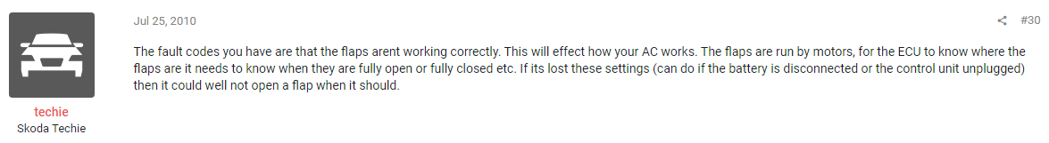
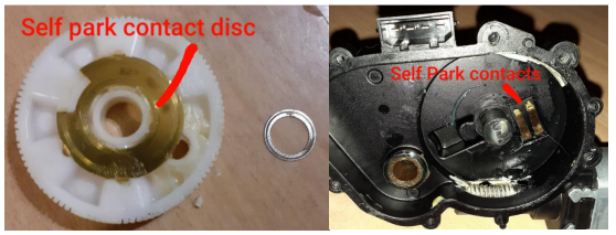
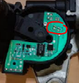
@ Nexus21 Are the front wipers operating correctly? To solve this, lets apply some reverse logic. You know that you have power, as the wiper will work under certain circumstances. The CANBUS control is therefore working, but there is something telling the wiper to be "disabled" in all circumstances, except when in reverse. I am aware that the wiper is disabled when the boot is open. What happens to the boot interior light? is it on all the time, or does it go off when the boot is closed? Theory being that if the boot closed switch (or sensor if that is how it is monitored - I haven't checked how it is done) is not operating as expected, then perhaps this explains the lack of wiper operation as the ECU detects that the boot is open, so disables the wiper operation. IT is possible that the boot open detection is achieved by measuring the current drawn by the interior boot lights, but I don't know this for sure. When the wiper operates, does it park itself in the correct position? I see you replaced the wiper motor. There is a metal disc on the drive gear which contacts the fingers on the PCB, which tell the system when the wiper is in the park position. Is it possible that the metal disc is missing or damaged or the fingers are not in contact with the disc? You could measure the resistance between the two contacts circled on the PCB, which should be "short circuit" at all times, except when the motor is in the "park" position (The cut out in the metal disc is the park position, so one finger will loose contact with the disc in the park position),. To test this, you would need to get the motor away from the park position (by operating the wiper when the car is in reverse in your case), then disconnect the wiper motor fuse, to make the wiper stop away from the park position. You will probably need to remove the wiper from the car to access to the PCB after you remove the plastic cover on the motor, once you have moved the motor away from the park position. Good Luck
-
Hi MicMac, Did you brave the DIY clutch replacement? If so, can you offer any advice, as I too am planing this job on a Mk2 1.9Tdi with BXE engine, on the driveway, as the value of the car doesn't justify a garage job and as it not a daily driver, I can take my time, within reason! Also, did you stay with DMF of do a SMF Conversion?
-
Phew, I had a near miss with this company. I am looking at a SMF kit for my Mk2 Octavia 1.9TDi, but luckily saw all the negative reviews and will be looking elsewhere for a Kit. Has anyone had experience of National Auto, Borg & Beck or Comline SMF Kits? Russ
-
If you are interested, I did a strip down and motor brush "tweek" on my estate rear wiper motor, to get it working.
-
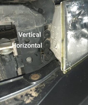
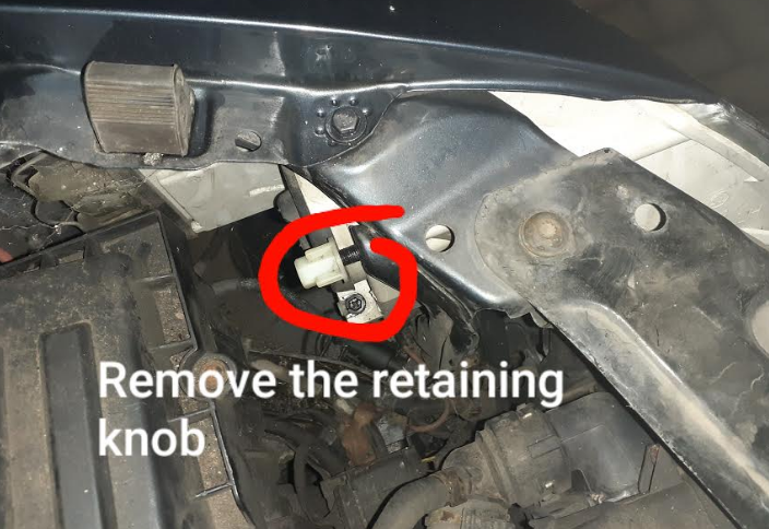
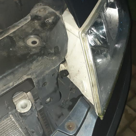
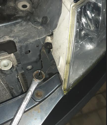
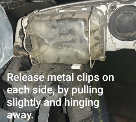
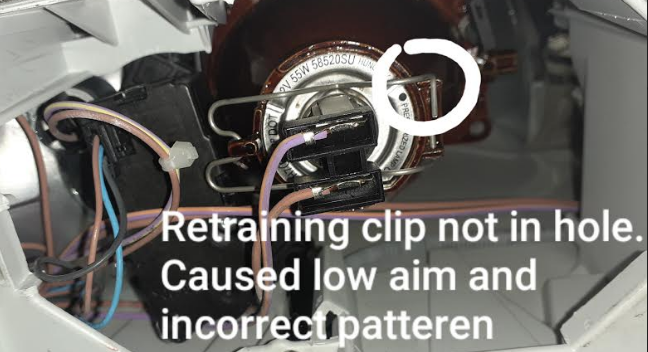
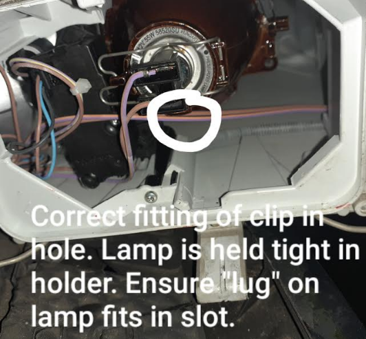
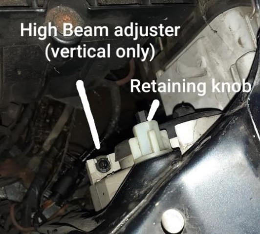
Hi I had noticed that the headlamp aim of the dipped beam was very low (just a puddle of light 2M in front of the car). I don't know the history if the car, so figured that the headlamp aim would be out. I initially tried the adjustment - the adjusters are shown below (Octavia 2 2007 Pre-Face Lift) the adjusters can be rotated with a 10mm socket or a 6mm Allen Key) - You can see the lens of the projector moving - a good reference is to make the gap between the lens and the reflector is equal. It achieved nothing!!! I decided to check the headlamp bulb. Remove the white retaining knob - it is screwed on by hand - the tightness does not affect the alignment. The high beam adjuster is also shown, and can give vertical adjustment of the high beam only, with a 6mm Allen key. Depress the retainer (just under the hook, against the edge of the light), and using a ring spanner or similar, pull the retaining hook sharply towards the centre of the car, this will cause the headlamp unit to move forward 20mm or so. It is now unlocked and can be withdrawn - have some towels or similar to protect the bumper from damage. May be worth having an assistant hold the headlamp to avoid it falling. It is possible to disconnect the electrical connector to remove the headlamp from the car. Swivel the headlamp unit out to get access to the dipped beam lamp holder. unlatch the clips to ether side - they stay attached to the headlamp unit, then pull the cover away. Examine the lamp and ensure that it is located correctly in the holder. In my case, the metal spring clip which holds the lamp in the correct position in the lamp holder, was not fitted correctly. The top right side of the spring clip had come out of the locating hole, meaning that the clip was not keeping the lamp pressed fully in to the holder, causing the lamp to aim towards the floor. With the clip inserted in the hole correctly, the "lug" on the skirt of the lamp should locate in the "slot" in the lamp holder. The clip is held in place (on the left side in this picture) and is unhooked by pressing the clip down (towards the bottom of the lamp housing) on left side of the clip, which allows the clip to disengage from the retaining hook and then to swing open, allowing the lamp to be removed. Once I had re-fitted the clip correctly, and re-fitted the lamp, the correct light pattern was produced (horizontal line with an angled up edge to the left). Refit the cover over the rear of the bulb and engage the clips. Carefully align the headlamp unit in the tracks of the retaining bracket and gently push it in until it stops. If it is difficult, ensure the "rails" on the underside of the headlight have engaged with the rails on the retaining bracket. Once the headlamp stops, push the hook in (using a ring spanner or similar), towards the headlamp unit, which will pull the headlamp in to its fully locked position, and the headlamp unit should be aligned with adjacent panels. As you close the bonnet, ensure that the bonnet does not hit the edge of the headlamp unit - it wont if you have fitted the headlamp correctly. Refit the plastic retaining nut on the top/rear side of the headlamp, inside the engine bay. The retaining nut tightness does not influence the headlamp alignment. Check alignment of headlights and adjust as required. In hindsight, the give away here was that the light pattern was, in MOT speak, "Obviously Incorrect". Had I checked the lamp fitment first, adjustment would probably not have been required. Always pays to check the simple things first, and never trust that someone else says they have checked it!

-
One thing I do know, is that the car was stood for some time and the battery was very flat (0.6V DC) but I managed to recover the battery and it starts the car fine now. I read on a Seat Cupra Forum https://www.seatcupra.net/forums/threads/climate-control-air-con-problem-help-before-the-weather-gets-hot-again.271744/page-2#post-3041470 That the motor position can be lost if the battery goes flat. I am guessing that Techie (Seat Forum) =Tech1e (Skoda Forum) = AKA Ross in Worcester? Thanks for any help anyone can provide. Regards Russell

-
Here is the VCDS procedure for performing the Basic Setting of the motor if the V68 Flap Motor is replaced in either the Climatic (Manual A/C or Climatronic (Climate Control Automatic system): http://wiki.ross-tech.com/wiki/index.php/VW_Golf_(1K)_Climatic#Basic_Setting
-
In the climatic (manual A/C) I think there is only one sensor: Which is in the centre of the three buttons which control the system (Heated Rear Window, A/C On & Re-circulate), which monitors cabin temperature, and adjusts the flap position to increase or decrease the flow of hot air, to achieve the setting on the temperature dial, which does have temperatures marked, implying that it is a closed feedback loop. The positions of the flaps to give air to feet, face or windscreen are mechanically moved with either cables or levers. The temperature is the same no matter what position the vents are in. As I posted before, if I perform the "test mode" (press and hold "Re-Circulation" and "Heated Rear Windscreen" for 1 second, the LED's flash and the temperature flap is moved between the extremes of movement (i.e. Hot and Cold) then returns to the position it was before. Here is a video to illustrate this test mode: https://drive.google.com/file/d/1NAGPJ8SdcwCtLkLfSXc2AReTeeWbYMV4/view?usp=sharing With the engine hot, If I enter the Test Mode, I feel the air change from cold to hot then mixed temperature, but I am setting the temperature control to Hot, but the flap doesn't stay in the "Hot" position" I don't know if this is the original motor or a replacement motor by the previous owner. The original motor end points should already be known by the car, but a new motor (or replacement potentiometer in the original motor) will need to have the end point set again. Any Ideas anyone of how to "re-calibrate" the motor position without VCDS?
-
Hi Thanks for the reply. I have seen that the climatronic versions have a hidden menu, where pressing the "ECON" and "Centre Vent" buttons with the ignition ON will perform a calibration of the flaps. By experiment, I have discovered that pressing the "Re-circulation" and "Heated Rear Window" buttons on a car with Manual A/C will cause the temperature flap to go to the hottest flap position (lever moves fully forwards towards the engine) then it will move to the coldest position (lever moves fully backwards, towards the driver). Then the motor will move to the current setting of the temperature control. With the engine warm, you can then feel the temperature change from Hot to Cold during the test mode. . This test routine doesn't seem to result in a calibration of the end positions, as when the temperature control is set to maximum heat, the flap motor does not reach its end of travel, resulting in slightly warm air, not hot air. So the flap motor is capable (both mechanically and electrically) of moving to each extreme of travel, but it is not where it needs to be. If there is an "on board" calibration for manual A/C, using dashboard button combinations, I cant find it
-
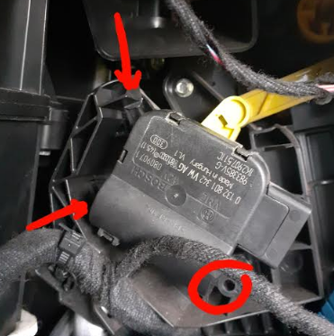
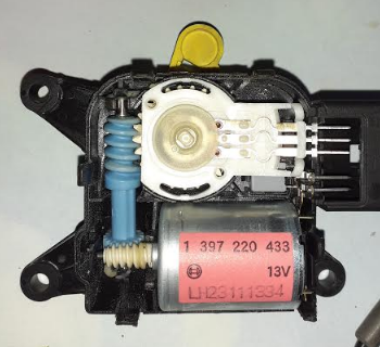
Hi I have a 2007 OCtavia 2 1.9TDi, with Manual Air con (not climatronic). It gets up to temperature, but I cannot get hot air from the vents. I have read about issues with the temperature flap motor. When I turn my temperature control to maximum cold, I cold hear the flap motor move. If I set temperature to the middle (12 o'clock)m position on the rotary dial, the motor could be heard, but if I move the control anywhere past the 12 o'clock position, no motor noise is heard. I removed the glovebox (6 screws), disconnected passenger air bag switch (with battery disconnected) and glove box light and cooling tube for glovebox, which allowed access to the flap motor. To remove the flap motor, release one screw (circled), then rotate the motor ant clock-wise slightly, then twist the motor to disengage the motor from the top retaining lug (which is on the opposite side to where the screw is), you can then unhook the motor from the yellow actuating lever. I opened the cover of the motor and then removed the feedback potentiometer (4.7K ohms). I cleaned it with electroninc cleaning spray, measured the resistance of the potentialmeter, which seemed good at all positions. I did note that there was an area at each end of the rotation which was "short circuit". Usually, these type of rotary potentiometers will have a variable resistance for about 300 degrees of rotation, with a linear change of resistance for the full rotation. I reassembled the motor and plugged it back in without re-fititng it to the actuating lever.. The motor moves, but only really when the control is towards the cold end of the temperature adjustment. Even towards the 12 o'clock position, there is no response from the motor. I have read that the motor position may need to be "learned" by the car, but I don't have diagnostics tools to achieve this. Can it be done any other way? If you look at the actuating lever on the motor, the arm seems to stop short of full travel at one end, and wants to carry on driving at the other end, characterised by a "ticking sound" which is the motor trying to drive when the mechanical arm is at the end of its physical travel. I can source a new potentiometer for £2, but will I still need to use VCDS to teach the system about the new potentiometer? Thanks in advance.
-
Good Tip - I watched a few You Tube videos, some used a "handle", some didn't. I didn't use a handle, and they worked fine, but I guess a handle would help.
-
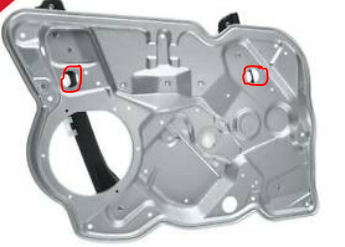
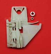
I just remembered that yours is the front regulator, so you will have two plastic brackets and spreader plugs to deal with, accessible through the holes circled.
-
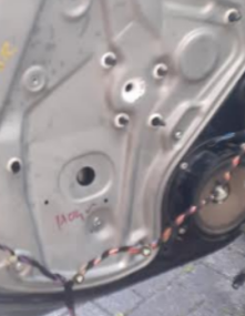
Before you try and get the regulator off, you need to separate the glass from the regulator panel track!! Assuming you already have the door card off, disconnect the motor plug, then remove the 3 Torx screws holding the motor and remove the motor. Remove the black rubber grommet which is just below and to the left (in this picture, you can see the hole where the grommet was). This will allow you to see the spreader plugs which hold the glass to the plastic regulator bracket, once you lower the glass - you can see the hole where the spreader plugs fit. Using some straight circlip or needle nose pliers, turn the white gear where the motor was fitted, and lower the window glass. As your plastic regulator bracket and or the drive wire are broken (which is why you are doing this job) lowering the glass may be a struggle, or may be easy, just make sure the glass cannot fall, so use a dent puller on the glass, like I did, to limit the travel of the glass or ask someone to hold the glass. When the glass is almost at the bottom of its travel, you should be able to see the spreader plug through the hole where the grommet was fitted. Use a M5 x 70mm screw, insert it into the smaller plug, then pull it the plug out, then use an M8 x 80mm screw and repeat the process from the larger plug. This will separate the glass from the plastic bracket. You can now lift the glass manually by pulling it up, then secure it with some tape or a dent puller on the glass. You can now drill the rivets out with a 10mm drill. Once all rivets are drilled out, you can extract the regulator panel downwards as the top of the regulator track extends a bit higher than the panel. You can use a length of woor to support the window from inside the door cavity for extra security while you fit the RivNuts. You can now open the holes out in the door panel (I would recommend a cone drill as above), then fit the RivNuts. Fit the large spreader plug to the hole in the glass (the large plug has a groove around the middle of it which allows you to locate it centrally in the glass) then fit the smaller plug into the large plug. Now offer the regulator into the door opening (remove wood if used), and adjust the position of the glass, to allow the spreader plugs to locate in the hole in the plastic bracket. Once it is located, adjust the regulator (using the gear where the motor was) and glass position, so that the regulator can fit into the door panel (there are 3 or 4 large metal dowels on the rear of the regulator panel to allow the regulator panel to sit correctly. Now fit the screws and washers to secure the regulator panel. Now fit the motor screws then re-connect the motor. Run the window up to the top and hold it there on the switch and then do the same at the bottom travel. This will allow the system to set the top and bottom travel, and then the window will work with the "one shot" function. Refit the rubber grommet Refit the door card. Good Luck
-
Good News! When you get your M6 set screws (Setscrews have thread all the way from the end to the underside of the head, bolts have a plain section under the head, then thread to the end), get some washers too. Make sure the screws are not too long. Mine are 10mm long, with a Torx T25 pan head (had some kicking about), but I would say 12-15mm would be better, to give a bit more thread into the RivNut. I would advise to keep the head choice as low profile as possible (say 4mm max) to avoid it fouling the door card when it is refitted. Remember that the factory rivets would only be about 2-3mm above the surface of the regulator panel, but with a screw and washer, it will sit a bit higher off the regulator panel. I don't know how much clearance there is between the regulator panel and the door card. Let me know how it goes.