

favguy
-
Posts
265 -
Joined
-
Last visited
Content Type
Profiles
Forums
Gallery
Shop
Events
Downloads
Everything posted by favguy
-
favorit rebuild
favguy replied to favorit33's topic in Skoda Favorit, Skoda Felicia, Skoda Fun and Skoda Forman
Hi, Had to laugh at the system treating S****horpe as a rude word!! I'm also only about 15 miles away from you. What year and model is your favorit? If you need an engine at all, I've got a perfect and very low mileage (19.5k!) engine available for a modest price due to my electric conversion :yes: Regards Paul -
Coming soon, the greatest Favorit project ever! (Probably)
favguy replied to favguy's topic in Classic SKODA Projects
OK, I made some good progress over the weekend and another milestone completed, the adapter plate and coupler finished, installed & tested Started with the motor end cap which came back from the machine shop looking very nice and more importantly, now flat, so started by re-installing this onto the motor: Next the coupler was fitted to the motor: The adapter plate was then bolted to the motor and the gearbox placed on top, aligned, clamped & finally drilled. Here's a pic. of it finished: The gearbox I've used for prototyping is sacrificial, so a large cutout was made in the top to observe correct alignment and true running of the coupling at speed, flats were ground around the bell housing to allow for clamping prior to drilling and the rear mount had to be hacked off to give access for some of the drilling! Sad for this gearbox, but I can now be confident the now finished motor and adapter will bolt directly to the cars gearbox with perfect alignment. A couple of pictures of the completed assembly rigged up ready for testing: And a close up showing the coupler in situ: I tested at 24v in 5th gear, running up to about 2500rpm, nice and smooth, no vibration at all, so should all be good. Next job is to strip out the cars engine bay, transfer the original gearbox to the motor and get the resultant drivetrain installed into the car. be back soon... :yes: Regards, Paul -
Coming soon, the greatest Favorit project ever! (Probably)
favguy replied to favguy's topic in Classic SKODA Projects
Hopefully the motor, coupler, adapter plate and gearbox will all be mated together and tested this weekend :yes: I'll update with piccies before Monday ;-) -
Coming soon, the greatest Favorit project ever! (Probably)
favguy replied to favguy's topic in Classic SKODA Projects
The adapter plate turned out to be very easy, the Favorit gearbox bell housing is nice and round, so easy to make a plate for. A 332mm x 332mm section of 25mm alloy plate was bought in. For those of you interested the alloy used for the coupler and adapter plate is 6082T6 grade, I believe it's aeronautical grade, so good enough for the Favorit It was taken to the local machine shop to be cut to 330mm outside diameter and 140mm internal diameter, with a part radius cut in the side to clear the half shaft. I then marked it up and drilled it for mounting to the motor: Once bolted tightly to the motor, we can move on to the final drilling for the transmission mounting, but..... :S We can't just yet, as it seems I overlooked something else... The motor was previously foot mounted and is now going to be used face mounted, it didn't occur to me when I drilled the face for mounting that the only part of the drive end housing that had actually been machined when the motor was made was the mating face to the steel yoke of the motor and the bearing housing, the face of the motor itself is as it came out of the casting mould and although that was fine in its previous life and it doesn't look to bad at a casual glance, it's not even close to the perfectly flat and true surface we need to mount it to the mounting plate and gearbox. So it's been removed from the motor and taken in to the machine shop to be worked over. I dropped it in this morning, once it gets back we can resume the fun. So that's all for now folks, be back soon. Paul -
Coming soon, the greatest Favorit project ever! (Probably)
favguy replied to favguy's topic in Classic SKODA Projects
And now for your entertainment, I present to you, the correct way to make a coupler... So having aquired yet another clutch disc, I set about grinding off the rivets and removing the unnecessary friction disc, leaving a nice shiny torque damper, this time to be used the right way around and mounted in such a way as to transfer the torque from the outer edge in as it was designed. If this is where you expect a picture, er.. sorry, forgot to take one at this stage! So... moving swiftly on... I now welded the hub to a suitable piece of 6mm plate steel, as both parts were over 5mm thick at the weld point, the juice could be turned right up and a nice neat heavy weld achieved. I then trotted off to the local machine shop to get it worked over on a lathe to the right diameter and have any runout removed so that it will run exactly true. following this a trip to the pillar drill for the mounting holes and here's the end result: Much better already I think! An alloy spacer ring was next made up from 5 inch round bar ordered cut accurately at 15mm and checked for complete flatness on a thick glass plate, turned out it was, completely flat that is! It was drilled out to suit and here it is finished: The torque damper had to be split apart in order to insert the new mounting bolts and to allow the mounting plate to be centred and clamped tight to the other components for accurate drilling, this involved grinding off the rivet heads, removing the original rivets and replacing them with high tensile bolts, threaded spacers and nuts. These were torqued up to the maximum recommended and then the bolt end "rivetted" over the nut to ensure they stay as tight as the original rivets: The next set of pictures shows the build up sequence to finished: I'm pretty happy with the end result and think it should now go the distance, only time will tell So whilst on a roll from the coupler being finished I moved on to the adapter plate.. -
Coming soon, the greatest Favorit project ever! (Probably)
favguy replied to favguy's topic in Classic SKODA Projects
Hi all, I'm back ... Well I've been doing a little bit behind the scenes, but mainly waiting for parts to get machined and turn up etc. but now I've a bit of an update for you all. The motor to gearbox coupler and mounting plate are finished, yeah!!, this is one of the most important parts of the project and has to be exactly right, and on that note I'll give you all a laugh by showing you my tragic first attempt at a coupler followed by the correct way to do it Although I neglected to take a photo of it prior to cutting it up, my motor came with a useful female attachment (no giggedy's or other comments please! ) that had big lugs on it to attach it to the original drive shaft or whatever in its previous life, having cut these off leaving the hub, I now needed to end up with this on something that in turn would go onto the gearbox input shaft. Due to the very high starting torque from the motor, I also wanted some form of dampening to "cushion" the power transfer, the ideal thing being a torque damper from an original clutch disc. So after not really enough thought I concluded that using an existing damper back to front got me the right distance onto the gearbox input shaft and that I could weld directly onto this! So I went ahead and welded the hub to one of the damper plates: (I can already hear those of you with engineering backgrounds tutting about why this is so bad!!) I then realised that the springs in the damper come on one set at a time in a staged way, and only do this in one direction, so using it backwards meant they wouldn't work properly, so to continue polishing the turd I was now committed to, I altered the spring carrier to suit: And here it is finished: And the re-assembled finished job in all its glory: I ran it up on the motor, got a cup of tea, stared at it for 5 minutes and thought about it, then promptly took it off, ground the hub off it and threw the remains in the scrap bin swearing about the amount of time I'd just wasted!! :wonder: For the following reasons: 1, The heavy cast steel hub was welded directly to the 1.5mm thick damper plate, which is made of very, very, hard (and a bit brittle) alloy steel (it destroys HSS drill bits when you try to drill out the pressed holes!), I'm pretty sure it would crack in short order at the weld edge due to this. 2, The torque would be transferred from the centre out to the springs, the damper was designed to do exactly the opposite of this... asking for failure. 3, It was impossible to get the spring action progressive when running it backwards, after the welding mod, all the springs would work together, at least to a degree, defeating the point of having the damper in the first place! 4, As if that wasn't bad enough, it didn't run true anyway due to distortion caused by welding to the thinner steel. 5, And finally, you know when something just looks like a crappy design and you just know it's not going to work right.. well it smacked of that (even before i'd completed it to be honest!) So there you have it, one great big crappy failure. So shall we start again?... -
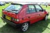
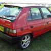
Hi, Unfortunately most car paint chips more easily than it used to due to the use of water based paints (envioronmentally better, durability wise far inferior) instead of the old 2 pack paints. It also gets damaged far more easily from bird ****, even leaving any on there for an hour or two in the sun will badly mark the paint, so keep an eye out for it! The good news is your car is made of galvanised steel, so won't rust much as a result, if left it will eventually spread and blister though if the chips are through to the metal, if they are only through to the primer it's not so bad. Best bet is to clean thoroughly and touch any through to metal chips in before winter weather. Paul
-
Coming soon, the greatest Favorit project ever! (Probably)
favguy replied to favguy's topic in Classic SKODA Projects
Hi Phil, Well as for performance figures... it's a bit of a lucky dip to be honest as the motor I'm using was never designed for it's new application and didn't come with any performance data, however... below is a performance graph for a Warfield Impulse9 motor, this is of very similar electrical construction, build and weight: Bear in mind I'm running 144v and not 72v as per the graph. (I hope the graph means something to you, as I can't make head or tail of it !!) Also, you can't directly compare HP for a petrol/diesel engine to an DC series wound electric motor, this is because you start with 2.5 times max. torque at zero rpm, and it drops away with increase in rpm's, then you change up and get the torque back, kind of exactly the opposite to an internal combustion engine! -
Coming soon, the greatest Favorit project ever! (Probably)
favguy replied to favguy's topic in Classic SKODA Projects
Well if I use 160Ah cells (largest I will use, might go with 100Ah's yet) they will need about 170Ah's in allowing for losses, so assuming an 8 hour charge, charger output needs to be at 21.25A, with an output voltage at about 156v to charge the pack. Voltage and current is inversely proportional, so with 230v in, charger will pull 14.41A, in reality at 90% efficiency, it will pull about 16A. Perfect for standard blue 16A socket and lead As for cost this equates to 3.68Kw, so x 8 hours equals 29.44KwHrs @ 12.902p per unit (BGas Day), at standard tariff so, thats £3.79, although the night rate is only 4.497p and thats when most charging will be done, so that's only £1.32 for about 80 miles But then we need to add the cost of a battery cycle, assuming battery cost of £7,000 (that's why I might be using the 100Ah's @ £4,500) and cycle life of 2000, that's another £3.50, so total cost of £4.82. For comparison, a diesel doing an average of 55mpg would cost you about £9.25 to do the same trip. this of course ignores wear & tear and servicing costs. (No exhausts, oil, filters etc. with the electric option)! By the way, I haven't forgotten you all, done a lot behind the scenes, mounting plate is at the machine shop, the coupler was designed and tested, a big fail! So 2nd prototype has been designed and tested and is now great, needs to go into the machine shop for a finishing tweak in the lathe that can't happen until I get the new clutch plate, so I can strip out the torque damper All will become clear soon... Paul -
felicia top speed
favguy replied to uma1998's topic in Skoda Favorit, Skoda Felicia, Skoda Fun and Skoda Forman
Once, a few years ago now, I needed to test my 4.2 A8 I had at the time having overhauled all the suspension links, took it up to 155mph on the M180 It was 2am on a summers evening and utterly devoid of all traffic I'd add! It's not speed itself, but the inappropriate use of speed thats the danger.. -
Coming soon, the greatest Favorit project ever! (Probably)
favguy replied to favguy's topic in Classic SKODA Projects
Hi st3f4n, Would love to show you the car some time Ok, making slow progress, got lots of materials on route at present, until they all turn up, I can't do a great deal. I did pick up a spare transmission cheaply, this will allow me to prototype and build the adapter plate and coupling and mount and test the motor without risking damage to the cars original box, also means I can drill big holes in it to check alignment and run out at speed in the bell housing, wouldn't want to do that to the oringinal I have a blog on an electric car site and one of the motor guys on there asked if I'd re-fitted the "wavy washer" on re-assembly of the motor! Turns out this was missing, presumably left out from prior maintenance, it pre-loads the bearings and takes up end float, so is quite important, it sits behind the bearing in the control end of the motor. So I whipped this off again and inserted the right washer, got to love the internet, I'd never even heard of these before, and 10 minutes later had sourced the right size and ordered one!, here it is: Meet the new brushes, same as the old brushes I decided to order a new set of brushes after all, although the old ones were in good nick, as they did look a bit low with wear. Well, turns out the new ones were virtually the same length!!! doh!!! Apparantly they are meant to sit that low in the holder when new, anyway, I'll console myself with the suppliers comment that they are a new graphite compound that minimises commutator wear! I did also give the motor a quick circumcision!! Compare with an earlier picture of the output shaft and you'll see what I mean This is in readyness for the coupling mounting, which will now be locked in place with a grubscrew, all will become clear soon.. And finally, although I didn't bother photographing it, I've changed the 8 bolts holding the end caps to the steel casing to high tensile grade 8 bolts and set them to a higher torque setting than before. I did this after noticing the originals had no head markings, meaning they were ordinary softer steel (probably grade 2). Makes sense I think as the motor is now going to be running at much higher voltage, current & speed than before. OK, thats it for now, for what it's worth, back soon... Paul -
Nice job, Watch the sides in those car parks now that they're smooth though!!
-
Used clutch plate wanted!
favguy replied to favguy's topic in Skoda Favorit, Skoda Felicia, Skoda Fun and Skoda Forman
djaychela, Not sure if you got the PM OK, as not heard back yet, can you drop me a line at paul(at)newmanfinancial(dot)co(dot)uk please so we can arrange things Regards, Paul -
Used clutch plate wanted!
favguy replied to favguy's topic in Skoda Favorit, Skoda Felicia, Skoda Fun and Skoda Forman
djaychela, I've sent you a PM wayne247, If you'd like to see pictures of the build as it progresses, I have a thread in the Project Journal section of the site, although we are a little of completion at present! Best regards Paul -
My Favorit
favguy replied to flipper's topic in Skoda Favorit, Skoda Felicia, Skoda Fun and Skoda Forman
This sounds great, can't wait to see the pictures Paul -
Used clutch plate wanted!
favguy replied to favguy's topic in Skoda Favorit, Skoda Felicia, Skoda Fun and Skoda Forman
Not in the slightest, assuming they use the same spline Paul -
Hi All, As some of you might have noticed on the project journel thread, I'm converting a Favorit to electric drive. As a result of this I need an old clutch plate/friction disc for prototyping reasons, doesn't matter how worn out and knackered the disc is, as I only need to strip the splined centre from it So if anyone has one from a recent clutch change, either Favorit or earlier felicia will do, I'll happily pay you postage and something for your trouble for it, please let me know. Best regards, Paul
-
Coming soon, the greatest Favorit project ever! (Probably)
favguy replied to favguy's topic in Classic SKODA Projects
Yes, That's exactly it, the physical work is to just rotate the brush assembly (in the head of the motor)in relation to the pole shoe position. In this case anticlockwise, as it runs clockwise looking from the head assembly. As for the stuff you said about speakers :S I'll take your word for it lol!! I know less than nothing about ICE! Regards, Paul -
Coming soon, the greatest Favorit project ever! (Probably)
favguy replied to favguy's topic in Classic SKODA Projects
Advancing it...well, first you need to fully understand DC motor theory, and in particular, series wound DC motor theory, I won't pretend I do, I had a look at the formlae for it the other day and got a serious headache after 10 minutes! I just do what I'm told by a very well renowned and trusted DC motor Guru I know of in the US! But here's the jist of it: Advance for a motor is shifting the brushes towards the direction of rotation slightly. The best position for the brushes to contact the commutator is midway between the north and south poles, or neutral. However when the motor is under load, the magnetic field of the armature distorts the main field (from the stator) and shifts it so the "magnetic neutral" is no longer aligned with the mechanical neutral. This shift causes induced voltage in the armature coils as they exit the brush and cause arcing. This isn't a problem at forklift running voltages of 36/48v, but becomes much more of an issue as voltage increases to much higher levels. One can compensate by shifting the mechanical position of the brushes to align with a "best guess" to where the magnetic neutral will be and reduce the amount of arcing under load. This arcing increases with voltage, current and speed, or any two, or any one of the three. That is why I say "best guess", because the EV traction motor is always changing voltage, speed and current as it accelerates. So, rules of thumb, and advice from experienced motor specialists are what most rely on. If the arcing at the commutator gets too severe, you can end up with it "zorching" a ball of plasma running around it similar to what you get from an arc welder, needless to say, if this happens the motor becomes a very heavy doorstop The rule of thumb for running at 144v is an advancement of between 10 & 12 degrees. So I've gone with 12 as I'd rather be safe than risk killing the motor! -
Coming soon, the greatest Favorit project ever! (Probably)
favguy replied to favguy's topic in Classic SKODA Projects
So, exactly 2 weeks from picking the motor up in it's original sorry state, everything was double checked and it was powered up from a large 12 volt battery for testing and run for an hour to help re-seat the brushes and observe it for proper function. As it had no load and the brushes were advanced, even at 12v it purred up to around 1500rpm as smooth as silk A few finished piccies: And just to remind you of the contrast with how it started lol!! : So there we have it, next job is to strip out the existing engine and transmission from the car and start working on the mounting plate to the transmission and the coupling. Back soon... -
Coming soon, the greatest Favorit project ever! (Probably)
favguy replied to favguy's topic in Classic SKODA Projects
OK, now the exiting bit starts, we get to build it all back up... First the front end cap onto the armature: You'll notice the top bearing has also been pressed onto the armature prior to the build up. Then the main casing is lowered into place (having first been painted Skoda Sportline Red to match the car ): Then the head assembly is carefully added to make the motor whole once more: In the end I put the original brushes back in as having inspected them, they were in really good order, along with new brush tension springs, the end result is quite neat: -
Coming soon, the greatest Favorit project ever! (Probably)
favguy replied to favguy's topic in Classic SKODA Projects
Whilst apart, the front end cap needed some work also. The lifting tag was removed as it will be of no use now that the motor is going to be face mounted to the transmission bell housing via an alloy plate. The face was then drilled and tapped for 4 x 3/8 UNC mounting bolts. (personally I prefer metric, but the rest of the motor is UNC, so it seemed bad practice to "mix and match" on the motor itself) Then moved on to build up the brush assembly and bus bars in the head: OK, next job was to press the new bearing into the front end cap: -
Coming soon, the greatest Favorit project ever! (Probably)
favguy replied to favguy's topic in Classic SKODA Projects
OK, So we'd got to having the motor taken apart, cleaned, old paint stripped and etch primed. So each section of the motor was now worked over as necessary, the main casing had the field coils removed and cleaned, then re-varnished using 1200v high temperature impact proof insulating varnish! The casing inside wall was then insulated with Nomex Polyester Laminate again rated at 1200v, high temperature to avoid any possibility of a ground short in the future. Whilst the casing was stripped out, I also re-drilled and tapped it to allow the head assembly to be rotated 12 degrees anti-clockwise for brush advancement. This turned out to be fun, as 3 holes drilled out just fine then the 3mm pilot hole drill bit decided it would be fun to snap off in the 4th hole at 20mm depth 3mm below the surface of the hole!! Anyway, 6 hours later.... after a combination of drilling down onto the top of the broken bit with a 5mm combination masonary/metal bit on hammer action! (usually useless but better than HSS bits for this task!)then disintegrating it with a narrow pin punch about 1mm at a time, then drilling down another 1mm, etc.., the ba***rd thing was finally out! Unfortunately, after completing drilling the hole, it was now far too "slack" to tap succesfully, so it was drilled out oversize and tapped for a helicoil, with this fitted the job was done at last, the remaining 3 holes took all of about 20 minutes to tap out perfectly! The pole shoes were re-painted and the casing re-assembled: Following on from this, the end housings were top coated metallic silver along with the fan. The brush assembly was then washed with phosphoric acid to remove the build up of carbon and re-assembled to the head. The fan was re-attached to the armature, after first blowing out about 30 years of compacted dust from the armature windings and inspecting it. Here we are so far: -
Coming soon, the greatest Favorit project ever! (Probably)
favguy replied to favguy's topic in Classic SKODA Projects
Well... Although my motor isn't a Warfield, they do a motor that looks just like the finished version of mine (see more below!) and it's called the Warp9 lol!! Apparantly owners of these motors are often heard quoting Captain Pickard and shouting "Engage..Warp 9" as they set off... -
Coming soon, the greatest Favorit project ever! (Probably)
favguy replied to favguy's topic in Classic SKODA Projects
Hi all, Just realised post No. 66 was still showing my first (crappy!) effort for the battery cell monitor display, so I've re-written it with the new pics. of the re-worked effort, a vast improvement me thinks... As for the motor, well, it gets finished tomorrow, so I'll have the during restoration and finished pics. up here within the next couple of days, you simply aren't going to believe the contrast with how it started out!