
favguy
-
Posts
265 -
Joined
-
Last visited
Content Type
Profiles
Forums
Gallery
Shop
Events
Downloads
Everything posted by favguy
-
Coming soon, the greatest Favorit project ever! (Probably)
favguy replied to favguy's topic in Classic SKODA Projects
Just a tiny update for now. I got my custom made grill badge back from the manufacturer today, so the car has now been re-branded to "FAV-E" (short for Favorit Electric of course ) -
Colour of new body panels/wings
favguy replied to j2sound's topic in Skoda Favorit, Skoda Felicia, Skoda Fun and Skoda Forman
Hi Craig, I don't have experience of using Halfords paint, but the professional convenience paints such as Upol matts/satins sold in rattle cans are exactly the same formulation as gloss finish coats, they use a matting agent at 5% to 10% solvent volume to lose the gloss. They are not water permiable and specifically designed for finish coat use. I checked the above with my supplier this morning . Probably best to avoid the cheap (quality, not price!) Halfords crap! -
Colour of new body panels/wings
favguy replied to j2sound's topic in Skoda Favorit, Skoda Felicia, Skoda Fun and Skoda Forman
@ craig1010cc What type of paint are you referring to when you say matt & satin black is porous? Unless you are talking about water based, my understanding is the paint is the same as finishing gloss but with a matting agent added to avoid the gloss finish, for example I've used Upol satin black for years (on top of prepped primer coats as I would with gloss top coats) on under bonnet metalwork & bracketry etc. I've never had any rust issues as a result?? Best example is a 1955 Beetle tank I did satin black during a restoration in 1989 it's still sat in my garage now and is as good as the day it went on! -
Coming soon, the greatest Favorit project ever! (Probably)
favguy replied to favguy's topic in Classic SKODA Projects
Finally it's legal!! Had a trip to the DVLA at Beverley today, no hassle at all and the car is now registered as an Electric. And the best part is the "NIL" duty rate, so I splashed out and went with 12 months. I owe you all some more pictures of further progress to date, I'll be back as soon as I get a chance to take some. Paul- 326 replies
-
- 16
-

-
16k felicia.
favguy replied to tedvegas's topic in Skoda Favorit, Skoda Felicia, Skoda Fun and Skoda Forman
I thought all felly's came with the strut brace as standard ? Those wheels are just incredible, fantastic looking car -
Felly 1.3 pinch bolt
favguy replied to greengoddess69's topic in Skoda Favorit, Skoda Felicia, Skoda Fun and Skoda Forman
Can I clarify something important regarding the B&Q suggestion above. Most bolts at B&Q are cheap "common" bolts, you can tell these as they have no markings on the bolt heads. This type of bolt is not high tensile and should never be used for safety critical work such as a ball joint pinch bolt or any other suspension related work for that matter. The type of bolts you need should be marked 8.8 on the head or above, nuts should be marked with an 8. -
Coming soon, the greatest Favorit project ever! (Probably)
favguy replied to favguy's topic in Classic SKODA Projects
An inaugural voyage, and the longest MOT... I've been grinning like a demented cheshire cat all day today. I'd been scurrying around all weekend finishing off bits and pieces ready for the MOT test today. So at 8:45 this morning I set off to the appointment with some apprehension, being the first time on the road, and the first time the car would be used "properly" with the controller, cabling and management systems installed and beyond the previous 24v "on/off" test I did around the yard after fitting the motor. So, with some very gentle throttle we set off out of the workshop and down the drive to the public highway, so far so good, no unexpected noises. Once on the road, a bit more throttle and off we went, changed up through 2nd, 3rd, and into 4th as the car got close to 50mph. All nice and smooth, no vibration and just a hint of that fantastic electrical motor whirring noise as the RPM's increased. The car is currently running 72v of used 110Ah Varta batteries and I really didn't expect it would accelerate very well or maintain much of a speed over 40mph. In the event I think it would have approached 60mph if I'd kept on giving it enough throttle, but I didn't want to push anything on the first trip. Average current to hold about 30mph on the level was around 80A to100A, accelerating was pulling 200A to 300A and I just touched 400A at one point accelerating up a slight incline. It all seems to be in order and would suggest a pretty low Wh/m figure. I'm really very happy so far bearing in mind it's running on crappy batteries at only 72v. I absolutely can't wait to get it running on 144v of Lifepo4 now... So, got to the garage and showed it to the MOT tester, who was firstly astounded at the condition of my 18 year old car, then gobsmacked as I showed him the fact it was now electrically powered and instructed him how to power it up for use. I ended up putting it on the lift for him and doing the brake roller test myself under his instruction, as he was nervous about driving it. He did insist on calling everyone else over to stare in awe at the engine bay and under carriage!! It really was quite surreal. The fun ended with the garage owner, about six mechanics and a passing customer milling around and under the car, the MOT took 90 minutes in the end, 15 minutes was actually the test. Great fun this EV thing... Oh, needless to say it passed... Merry Christmas everyone- 326 replies
-
- 14
-
-
Favorit vs Felicia wiper blades?
favguy replied to favguy's topic in Skoda Favorit, Skoda Felicia, Skoda Fun and Skoda Forman
lol! I wonder how much you could get away with, for example using an old flat screen beetle blade, I think they were only about 12" long -
Favorit vs Felicia wiper blades?
favguy replied to favguy's topic in Skoda Favorit, Skoda Felicia, Skoda Fun and Skoda Forman
Yep, 20" fit perfectly -
Favorit vs Felicia wiper blades?
favguy replied to favguy's topic in Skoda Favorit, Skoda Felicia, Skoda Fun and Skoda Forman
Thanks for the reply, I'm going to try a 20" set today, so I'll let you know if they fit later -
Coming soon, the greatest Favorit project ever! (Probably)
favguy replied to favguy's topic in Classic SKODA Projects
Hi Guys, Well.... the MOT is finally now booked for next Monday at 9am, I decided the car needed some TLC to the non EV conversion side of things before the MOT. So I fitted a few new bits.. Front and rear Shocks Front springs (lowered), to correct the stance due to the rear sitting lower due to battery pack) Front Brake discs and pads Rear Cylinders and shoes Master Cylinder Lower control arms Track rod ends The shocks were all working fine but had all rusted so severely I was worried about the springs coming through the support cups! It's odd that the car is almost totally free of any trace of rust underneath, yet the shocks were just horrendous, looked like they'd been salvaged from the titanic! The master cylinder seal was weeping slightly, probably due to sitting unused for a few years. One rear cylinder was also weeping a little and the other had seized up. The front discs were just quite worn, (original from new) rusty & pitted from lack of use. The nearside lower balljoint was worn, the wishbones generally tatty with rust and in any case after 18 years the car will benefit from having all new bushes. The track rod ends had torn boots from removal during the conversion, so needed changing. Add to that lot a new set of wiper blades and were all good to go for the MOT on Monday, It should sail through hopefully. I've got some more pics to post soon of the main cabling install and rear battery, I'll add them after the MOT 'till later... -
Hi All, I just noticed whilst looking to pick up a set of new front wiper blades for the Favorit that the listing in the book showed 18" for the favorit and 20" for the felicia. As both cars share exactly the same size windsreen glass, can anyone advise if the 20" will fit the Favorit at all? (I have always thought favorit blades looked a size too short,so maybe!) Regards, Paul
-
Coming soon, the greatest Favorit project ever! (Probably)
favguy replied to favguy's topic in Classic SKODA Projects
Forgot to add, there are no additional MOT checks for an electric car other than the usual cables and batteries must be secure etc. In fact the test should be a bit faster, with no exhaust, emmissions, or fuel lines to check. -
Coming soon, the greatest Favorit project ever! (Probably)
favguy replied to favguy's topic in Classic SKODA Projects
Hi all, Will usually set off in 2nd unless on a very steep hill, could probably even use 3rd, but the acceleration will be a little slower. There is no clutch, the motor is linked to the transmission via a damped coupler (see earlier posts on this). A clutch isn't needed as there is no large rotating powered mass to remove as with the original petrol engine, just the additional few KG's of the motor armature, which isn't powered when the throttle is released, so you can change gear at will clutchless I'll have to be there during the MOT, as the tester won't have a clue how to start it! Starting sequence: Ign. on position gives accessories only along with brake pre-charge as needed (if not still under vacuum). To prepare for drive, the key is momentarily turned to the start position and the drive system relay latches. The drive system active (Amber) warning light comes on along with a Red pre-charge warning light. The controller is soft started by charging the capacitors through a resistor. After 8 seconds this is complete and the main system contactor now closes giving full pack voltage to the controller and the pre-charge warning light goes out. The car is now ready to go. (You can't go before this as the throttle is locked out). Simples!! -
Coming soon, the greatest Favorit project ever! (Probably)
favguy replied to favguy's topic in Classic SKODA Projects
Just realised, you may all not know why this matters. With a DC series wound motor, if anything more than a very low voltage, 12v-24v is applied to the motor at no load (ie. flooring the throttle pedal in neutral) the motor will almost instantaniously accelerate to a dangerously high RPM and could destroy itself and/or possibly the gearbox! -
Coming soon, the greatest Favorit project ever! (Probably)
favguy replied to favguy's topic in Classic SKODA Projects
OK, so I've got the control wiring finished and tested out at last . One thing that's been bothering me for a while is that an MOT tester, or any other third party for that matter can "blip" the throttle as you might in an ICE when the car is in neutral and we all know how that can end! So I built a throttle override switch to run in parallel with the throttle and keep resistance at zero when not in gear. The two microswitches are normally closed and wired in series so keeping the throttle locked out until either switch is activated by engaging a gear. One switch covers 1,3,5, the other 2,4,R. You can see it fitted below along with an additional control disk monted on the gear linkage. OK, that's it for now, just still got to run the battery cables to the rear boxes and overhaul the brakes, MOT is booked for next week, at last.. -
Coming soon, the greatest Favorit project ever! (Probably)
favguy replied to favguy's topic in Classic SKODA Projects
I've been working steadily on the car, the day job has, as ever, has kept getting in the way, but I'm very nearly ready for the MOT now. I've spent a a good full four days finishing up all the control wiring, building safety interlocks on the gear selector to lock out the throttle function when out of gear, installing the impact switch cut off circuit and manual emergency circuit breaker control, finishing the voltmeter/ammeter/temperature guages wiring etc.. Doesn't actually look like much progress actually, but seems to have taken ages. I've tested it all out with just 12v on the main pack at this point. All seems good. Just have to run the last battery box cabling now and then overhaul the brakes, and I'm off for the MOT Finished control box: Close up of the circuit breaker access for turning it off or resetting: -
Coming soon, the greatest Favorit project ever! (Probably)
favguy replied to favguy's topic in Classic SKODA Projects
The next shot shows the front battery rack in place, with two of the 110Ah Floodies present (I'm running a total of six of these initially, just to get road legal and test out the car and systems, then onto 144v nominal of proper lithium! ) Still got to do the battery hold down at this point. The next picture shows the control box with the main cabling done and the throttle and pot box set up. The 12v control wiring, pre-charge and instrument wiring is still to do: The next shots are of overall progress to date. The space left on the shelf is for future placement of the DC/DC converter. This will be run in conjunction with the small 40Ah accessory battery you can see in the rear right of the shots. The black grommet in the control box lid is to allow access to connect the emergency shut off cable to the main breaker once the box lid is on. That'll do for now, I'll be back soon, the plan is to have the car ready for, and MOT'd by the end of next week -
Coming soon, the greatest Favorit project ever! (Probably)
favguy replied to favguy's topic in Classic SKODA Projects
Right, I'm back, so much for getting on the road by the end of September... I've only got to finish some battery cabling, battery hold downs & 12v control wiring and I'm good to go for the MOT, I've done quite a lot of stuff over the last few weeks, so here is the update, in no particular order: Starting with the controller, I managed to find a nice heatsink on ebay, so this was cut down to size and monted to the base of the controller by drilling and tapping four M5 blind holes into it, not forgetting a nice layer of heat transfer paste: Should help keep it nice and cool. I also filled the last remaining space in the dash with an Ah meter. This way I can keep track of Ah's used and know how much range I'll have left. This was a bit of a case of fitting a square peg in a round hole, and after much head scratching to decide how to best make it work, decided to set it in place with resin. So I set up the casing in the dash cubby hole, having first cut out the rear of the hole for cabling. It was taped up liquid tight at the rear and I poured in black casting resin up to the level where the front face clips on. Turned out quite well I think: I'll throw this one in for good measure, although not directly related to the conversion: Got rid of the awful original wheel by replacing it with a nice stitched leather sports wheel, and also matching leather gearknob. Note the "Electric" logo I had made for the wheel centre! Anyway, back to the conversion... Braking system, Managed to get a nice new Landrover vacuum pump from ebay for a steal, along with an Audi vacuum chamber, and adjustable (to -30Hg) pressure switch and guage: Spent another few hours deciding on the best way to mount this lot and prototyping mounting brackets, then mounted it all together, think it turned out quite nicely: As you can see I've got to finish to control relay and wiring for this, but have tested it down to -30Hg and held it for a couple of hours with no loss of vacuum, so far so good. OK, so brakes are all but done, what's next?... Control shelf, construction, component mounting: Having thought about the best way to do this for some time, I ended up using a strut brace bar from a Felicia as an upper support for the shelf structure. The Favorit never had one of these, but as the Felicia's all got them, and as the Felicia is a rebodied Favorit.... it fits perfectly. The front battery rack then acts as the lower mounting point for the control shelf frame. I decided to build the shelf support frame from light weight galvanised angle as it keeps the weight down and is quite adequate for the weight of the control gear. It also saves me painting all that framework! I decided to go the simple route for the control shelf itself, using 12mm external plywood. Cut and machined it as needed, then sanded, primed and painted it. Primitive but effective. You can also see the front battery rack in the below pictures. This is built from more conventional 3mm wall thickness 40mm angle with captive nuts, and brackets welded in, so it drops right in and is bolted to the front outriggers in four places. The flat panel you can see is the closing panel to waterproof the engine bay at the front where the radiator was. I've also built an undershield to enclose the lower engine bay, It's not photographed yet, I'll come on to it later. Control shelf finished, controller mounted and 70mm motor/controller loop cabling finished: -
Coming soon, the greatest Favorit project ever! (Probably)
favguy replied to favguy's topic in Classic SKODA Projects
Hi All, Am working on the car all this week now, ready for MOT sometime next week hopefully, so should have lots of updates and pictures by next weekend. Thank you all for your patience Paul- 326 replies
-
- 11
-
-
Favorit suspension
favguy replied to Brogard's topic in Skoda Favorit, Skoda Felicia, Skoda Fun and Skoda Forman
Hi Stelladragon, Just out of interest what difference do you notice in particular with the strut brace fitted? Kind regards, Paul -
Coming soon, the greatest Favorit project ever! (Probably)
favguy replied to favguy's topic in Classic SKODA Projects
Hi Matt, This is probably what you're thinking of, circa about 1992-1994. They called it the "Eltra"
-
Coming soon, the greatest Favorit project ever! (Probably)
favguy replied to favguy's topic in Classic SKODA Projects
The controller has now been tested, so I fitted the end caps and sealed it up -
Coming soon, the greatest Favorit project ever! (Probably)
favguy replied to favguy's topic in Classic SKODA Projects
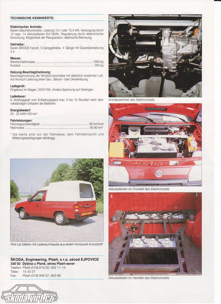
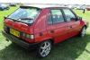
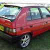
OK, I'm back with some progress at last!, Most of the original watchers of this thread have probably got bored and moved on by now as it's been so long since the last update !, I do know of at least some who have left Skoda for another marque and don't come here any more ! For those of you who are still watching the idea is to get the car at least road legal by the end of summer. I'm thinking I must be in the running for the longest ever project build time award or something! OK, so where had we got to... Controller first I think As already mentioned somewhere in the mists of time, the car needs a controller. As an analogy, if the motor was the cars heart, the controller would be the brain, but enough of that... It manages the cars motor current and voltage parameters under all driving conditions to give us the power needed on demand via the throttle to actually make the car drivable. Put simply, with the type of series wound DC motor used in the car, voltage gives us speed and current gives us torque. The controller therefore does a mix and match of the two to give us the power needed up to a maximum power of 72Kw, unlike a petrol or diesel engine maximum torque is available from 0 rpm. Bearing in mind the original engine was 60Kw with maximum torque only available somewhere way above 3000 rpm, the car should perform nicely I decided on an open source project controller for the car, the 500A Open Revolt. The parts can be gathered together to build this from various sources, but the developer of the kit, Paul Holmes, over in the US ( www.paul&sabrinasevstuff.com ) sells a complete kit of parts with excellent support for a very reasonable price, so I bought one from him. I have to commend Paul and all the others who've worked on this thing, it really is a nicely developed kit, also to Paul especially, for such excellent packaging and assembly instructions. I finally got to building it over the last two or three weeks, sailing through the control board build with my 30 watt soldering iron, but the 100 watt soldering gun I had wouldn't touch the power board due to the large ground plane sapping away the heat so quickly. (When the intructions say you need a 200 watt iron/gun, they mean it!) I finally sourced a 200 watt iron (from Germany at 1/4 the price of UK irons, why do we pay so much more for everything in the UK??) with the biggest copper tip I've ever seen on a soldering iron which did the job effortlessly due to it's large thermal mass. Below are a few pics of the finished controller, If you'd like to see the build procedure, it's available here: http://www.paulandsabrinasevstuff.com/VideoFilesMcontrollers.html Having scratched my head for ages over what to do at the end cap regarding the control wiring, as it's left for the kit builder to deal with this and I didn't want to leave it just sticking out, I came across an 8 pin Bulgin plug and socket. These are compact, well made (bieng designed for 230v use) and also just seem to "look right" The enclosure top turned up looking like nice shiny brushed Aluminium and I considered leaving it at this, but i'm pretty sure it wasn't anodised and due to our lovely damp UK climate that means it would have a not so nice white powdery oxide finish after a few months on the car so I gave it a paint system and finished it satin black. I might buy a nice "Open Revolt" sticker for it in due course. I've got to do some more testing then I'll seal it up and bond on the end caps using PU adhesive sealant and post a finished pic. In addition to the controller, I've done some more metalwork. Finishing the front battery rack, closure panel for the hole left by the radiator and modified, larger under shields to get the engine bay much more water tight than it was with the engine in it. I've also sourced all of the vacuum brake system parts, contactor, pack fuse and main breaker. I'll post picures of this up shortly. Oh, I've also sourced and installed an Ah counting meter in the last part of the dash not already filled with meters!! This will act as an accurate "fuel guage" for the car. I'll post up some pics of this soon also. So, we are slowly getting there. Left to do is build the control shelf above the motor, then it's component mounting, main pack wiring and conduits, control circuits wiring, battery placement, charger, DC/DC etc... Although the car has been built for and is going to have a 153.6v nominal (144v under heavy load) lithium battery pack, I don't have funding for this as yet, so I've acquired some lightly used 110Ah 12v traction batteries, 72v worth. These will be used to allow me to get the car finished to the point where it can pass an MOT test and be registered and taxed for use as an EV. I'm expecting initial performance with the 72v Lead to be modest, something like a max. speed of 45-50 with a range of around 10 to 15 miles, so not too exiting, but at least I can get it on the road. I'm aiming to have this milestone done by the end of September at latest. Be back soon, Paul -
Hi All, If anyone has a spare drivers side rear quarterlight window glass they'd like to sell, can you please let me know. Some retarded scroat has broken my mothers Favorits in a pathetic failed attempt to steal it! Many thanks. PS, Non tinted if possible Paul