BilTechnik
Finding my way
-
Joined
-
Last visited
Everything posted by BilTechnik
-
The check happens when the brake pedal is pressed, which explains why TKW method works. When you release the accelerator the throttle position falls to 0 and let’s the ECU pass the check, when you accelerate again the check isn’t ran as long as the brake pedal is still down.
-
You shouldn't be able to on a stock Fabia. The ECU has a check where if the thorttle isn't in the idle position (less than 1%) and the brake is pressed, the fuel ramps down to idle. There is a software switch to disable this check. It is also disabled if you have a faulty brake switch.
-
If anyone has a file they want this doing to, let me know and I'll do a guide. Takes 30 seconds with a hex editor
-
I'll complete the Guide section next week, but to summarise. I would rate this as Medium/Hard depending on how confident you are with wiring, and if you have any other reason to have the dash off. If you have all the parts the retrofit could be easily completed in a weekend. For most/all 1.9 TDI there is NO CODING required, just plug and play which is great. For 1.4 TDI it may work, or there may be a change that you need to make which I'll detail later, but you'll need an MPPS/Galleto or similar cable to do it, it can't be done via VCDS. I'll also upload some results measuring the temperature inside the cabin with/without the heater.
-
100% working PTC heater installed in a Fabia 1.4 TDI, fitted and working as it would be from the factory! Video - Copy.mov Off camera I'm turning the temperature dial from maximum to Minimum, in VCDS you can see that when the Dial is at Maximum, only the one "1" is shown on the second row, and the heating elements start to come on (third row). When I turn the dial down to minimum, a second "1" appears. That is the inhibit signal from the HVAC controller, and the heating elements immediately switch off.
-
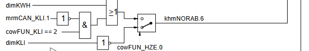
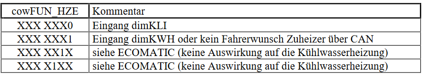
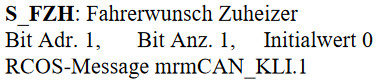
I decided to look in the FR (not an expert but can get by) for some clues, below is the flow chart concering "user-shutdown" of the PTC. It's sort of implied coolant heater but it is PTC So cowFUN_HZE is referred to in DAMOS as "Cooling water heater" and in the FR is reffered to as this The other bits are referring to ECOMATIC (start-stop). We want bit 0. So if bit 0 is 0, then "Input is dimKLI", which we can confirm by the diagram. When bit 0 is 1 (Input is dimKWH or no driver requst over CAN). Basically, when the bit is set to 1, the car is provisioning for PTC heater. If we go back to the diagram, you can see at the top, dimKWH going into an OR block. dimKWH is the physical ECU pin that connects to F268 on cars with no airconditioning. This isn't present on cars with aircon. However, the fact I am able to disable by PTC by shorting this pin to ground shows that the cowFUN_HZE.0 bit is set to 1, which is a good start. Looking at the other leg of the OR block, there is an AND block with two inputs. cowFUN_KLI is a byte in memory that is used to tell the car if it has no climatronic, climatronic without CAN or climatronic with CAN. Climatronic with CAN is specified when cowFUN_KLI = 2. When cowFUN_KLI = 2, decoding of the CLIMA1 CAN frames in enabled, this frame is transmitted by the HVAC controller. mrmCAN_KLI.1 is then the "Driver request of Auxillary Heating" transmitted over CAN from the HVAC controller. There isn't really any easy way of checking what cowFUN_KLI is set to without the correct DAMOS. I have 1.9 TDI DAMOS and in those cars, it is set to 2 as expected, but it is possible they just set it to 1 or 0 in the 1.4 TDI cars. Also, this only enables the ECU side of it, if the frames aren't being transmitted by the HVAC controller, and passed by the gateway then this still won't work. Next step is to keep looking for a 1.4 TDI BNM DAMOS file, and sniff the CAN frames that are being sent from the HVAC controller. Hopefully, the HVAC controller will be sending the requried information and it will just be a byte that needs changing in the ECU flash to turn the decoder on. If the frames aren't being sent, then I'll have to look at getting a D revision HVAC controller. For clarification, the cowFUN bytes are stored in ECU flash and need to be changed the same way you would remap the car, you can't edit them with VCDS for example.
-
Done some further testing, I suspect the wire being grounded could have been false and its actually floating, which would match the wiring diagram. If I ground the pin of the ECU, the PTC deactivates, and if i let the pin float the ECU pulls it up to 12 volts and the PTC activates. I know of @Finn vRS and @bigngroovy who have this from the factory (who I've messaged) but does anyone have it? Ideally with VCDS to check coding. The other thing I'm thinking it could be is I have 6Y0 820 045 C climatic module, which if you search on eBay, there are loads of. However, this is also a 6Y0 820 045 D specified, which isn't very clear what its for, just a different date range I think. So I wonder if that is the D variant has something to do with car which have aircon and PTC, aka have different software to transmit the PTC data over CANBUS. Again, if someone with PTC could confirm what module they have that would be great!
-
Yeah I only came accross it because it's about all the information there is. From what I can tell, the 6R is basically using 6N climate controls.
-
Yeah I think you're right, but there is something connected to the other end of it to ground the wire, and that's not shown on diagram which is confusing. Yeah it explains it here. https://polo.blue/2018/12/17/swap-manual-climatic-ac-to-climatronic-ac-part-1-comparison-theory/ So he doesn't show "semi-automatic" Climatic, but its the same as manual climatric, without a mechanical connection to the temperature control dial.
-
Okay so its all fitted, and it works! However, its not perfect. The ECU side works correctly, it switches on stage 1, stage 2, and then both stages (assuming alternator load is satisfactory). It also switches off when the coolant is above 80. But, the postion of the heater control dial has no affect on heater. So this means that the heater is always on, even when the temperature is set to cold. And that results in the heater just sitting in still air and getting very hot. That's probably safe but I doubt is how it's meant to work, and also waste fuel as its basically just heating up the bottom of the HVAC unit. From the SSP, it states that if the heater dial is above 80% it should engage the heater. If I go into VCDS and check the HVAC, there is a field for Z35 (PTC) acivation, and that does turn on and off based on the dial postion (although there is a large delay for it doing so). If I go into the ECU, and check VCDS, measuing block 16 shows information for the heater. Even when the dial is cold, the ECU goes through and engages the relays. There is a also a field for "Shut off conditions". VCDS lists things such as voltage, coolant temperature etc. For the heater to engage, all bits in that field are meant to be 0. However, the first one, which VCDS list as "Outside temperature above 5 degrees) stays at 1 regardless of outside temperature, and the ECU still engages the heater. To further confuse things, there is an error in the wiring diagrams. My car has air conditioning, so this connection to pin 15 on the ECU, from the "Heater setting above 80% switch (F268) shoudldn't exist. However, there is a wire going into pin 15, that is permanetnly grounded. I've not checked where the other end goes, need to have the dash off again to look. I've tried removing the pin from the ECU connector, so it floats to 5 volts, and the ECU still activates the heater. So my conclusion is there is possibly some incompatiblity between the ECU in my car and the HVAC controller. My car has a different ECU thank from the factory as it is remapped, and there is a chance that, even though its been flashed with the original data, there is hardware difference that is causing some odd behvaiour. I'm going to swap back to the orignal ECU and see if that gets me anywhere. If that doesn't help, I'm going to try a newer revision HVAC controller. I'm also searching for the correct contact assignment for the Fabia HVAC controller. It is "semi-automatic" climatic, in VW land. So it controlls the temperature via a moror. Currently, I can only find diagrams for climatronic, and fully manual climatic which are slightly different. That might offer some clues as to what I'm missing.
-
Fitted the heater back into the car today, which took far longer than it shoud have. I'm using some Xpanda foam tape which is good, but is more dense than the orignal stuff. I think this pushed the bottom of the heater box slightly out of shape. This combined with the firewall grommet that goes around the heater matrix made it almost impossible to fit. In the end, I had to get one side partially clipped in, and brace myself against a wall to force the otherside far enough for it to clip in too. I'll post some pictures tomorrow. Its all clipped in nicely now and isn't under stress, so I don't think anything is wrong. I may take it off again tomorrow to see if the foam has settled and nothing has been trapped, I don't want to be taking everything apart again if something isn't right.
-
Also the cutting of power in the first place is a safety feature, because its assumed the accelerator may be stuck, so you're trying to brake. The SSP also makes reference to the fact that, if one of the pair of brake light switches fail, then the ECU will reduce power.
-
The clutch pedal switch is there to make it easier to change gear. If you rev the car in netrual, clutch up, the revs fall slowly. If you put the clutch down, you'll notice they drop really quickly. Easier to tell if you keep blipping the throttle and moving the clutch up and down. I summise that with the clutch up, if you let off the throttle, the ECU keeps injecting some fuel so you don't get hit with a huge amount of engine braking. But obviously, when you want to change gear, you need to revs to fall quickly, so when the clutch goes down the ECU cuts more fuel. See SSP 209 for details on the above To disable this "nicely" you need to flash the ECU and change one byte. Need to use Galleto/MPPS or similar.
-
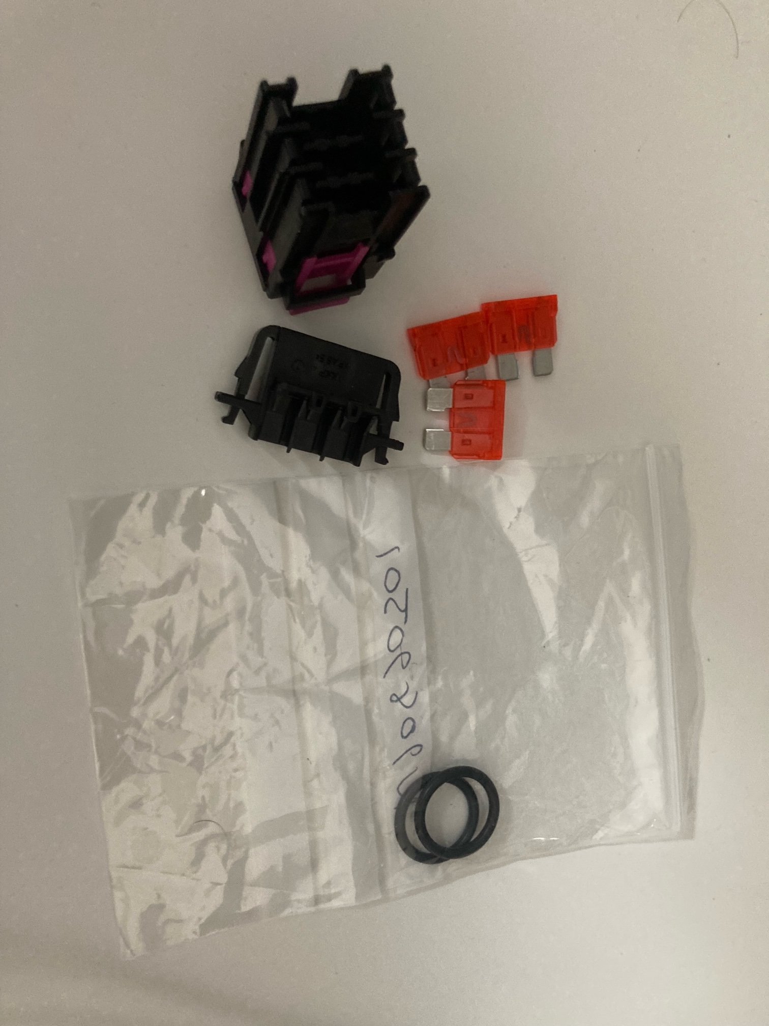
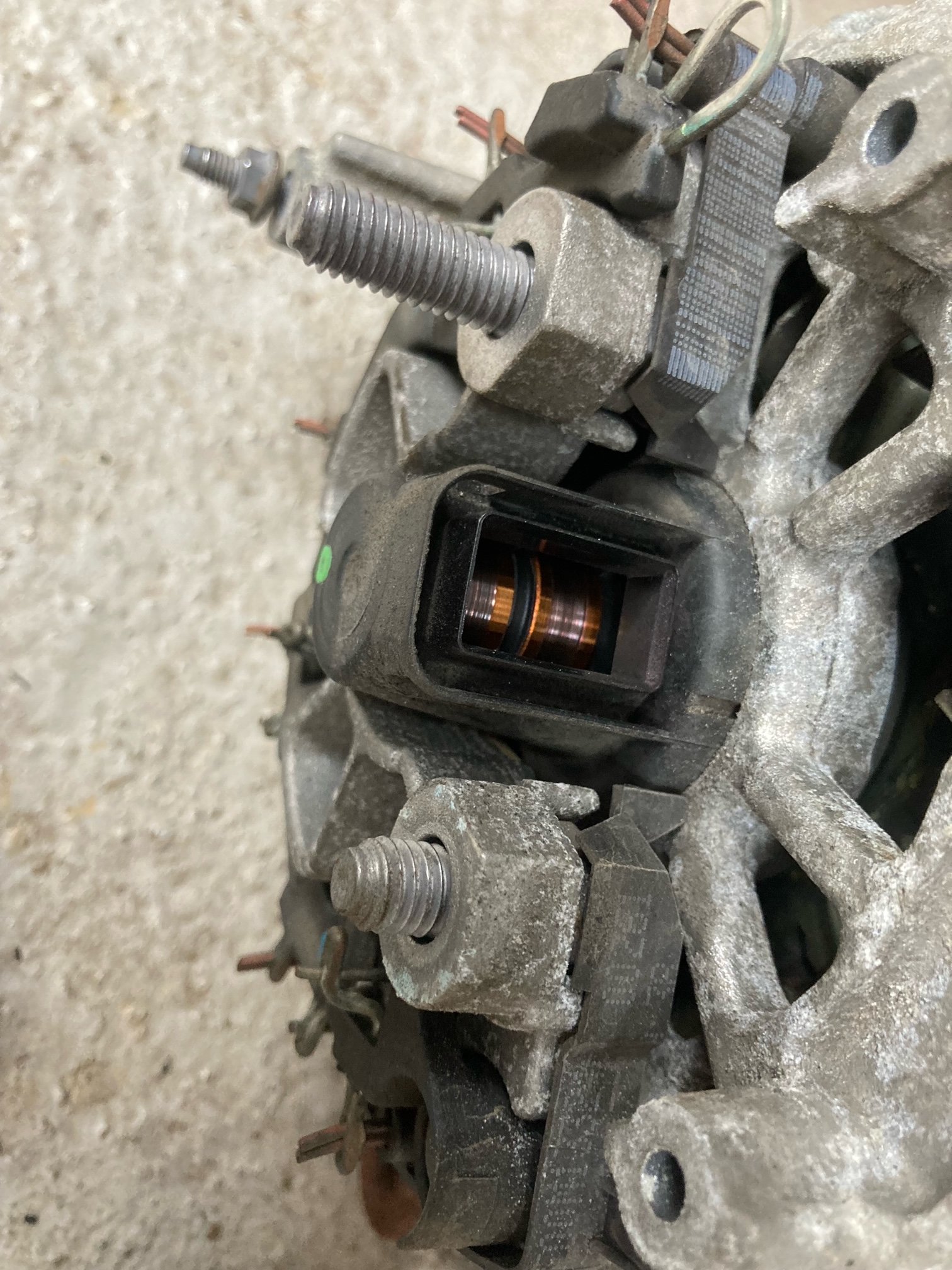
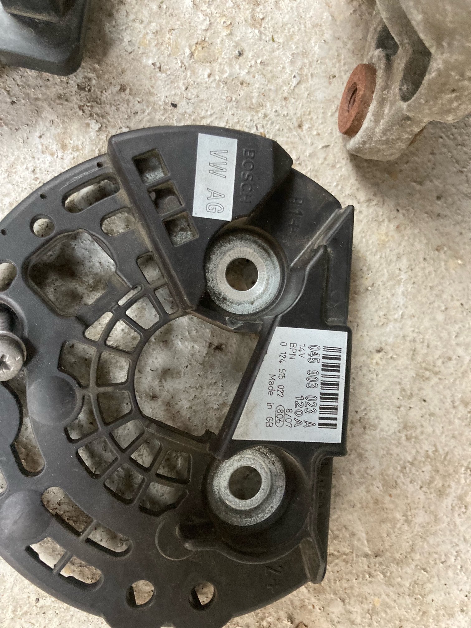
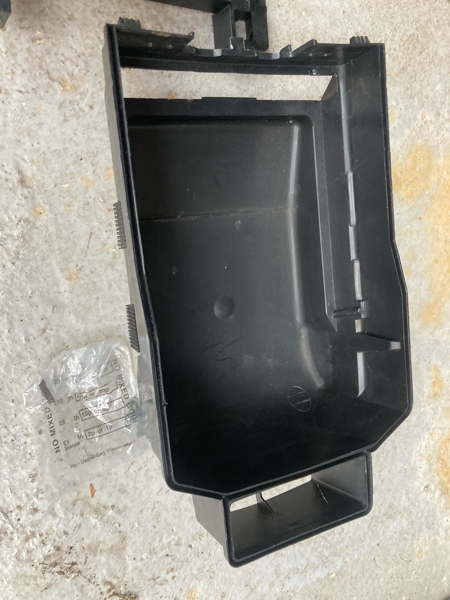
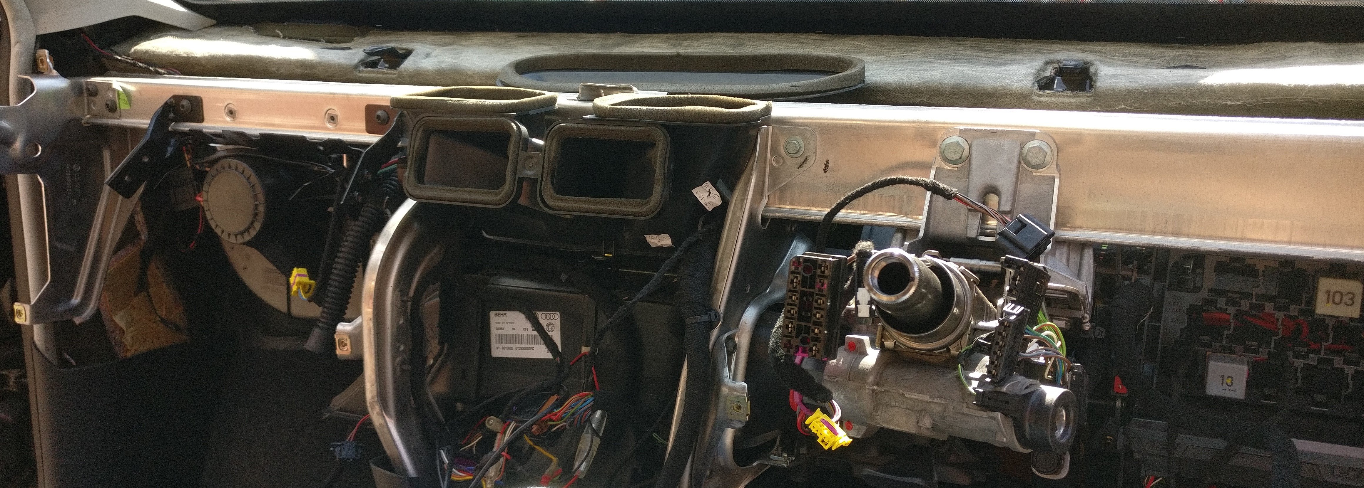
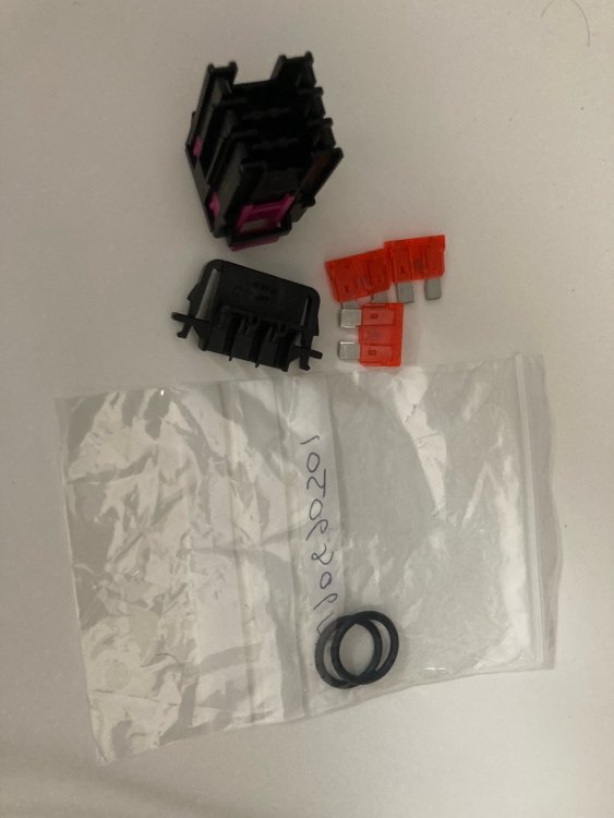
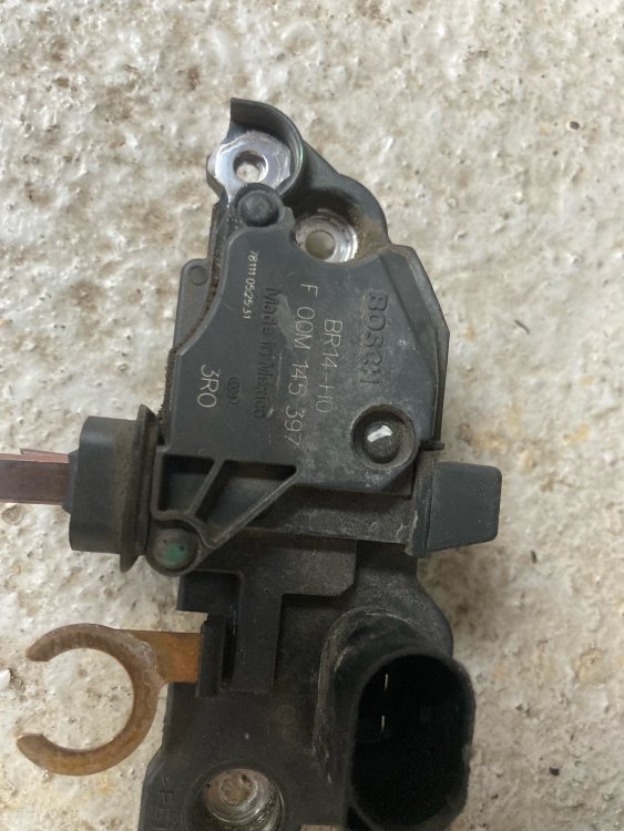
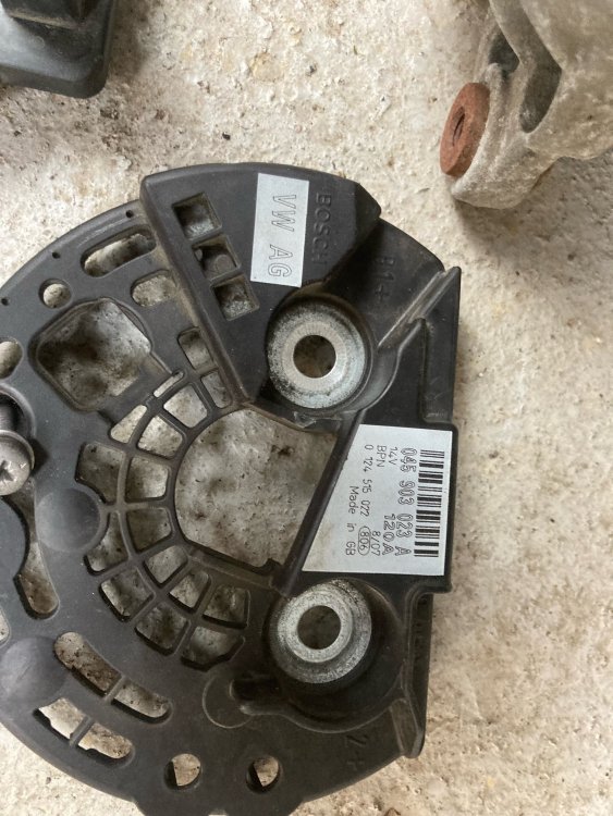
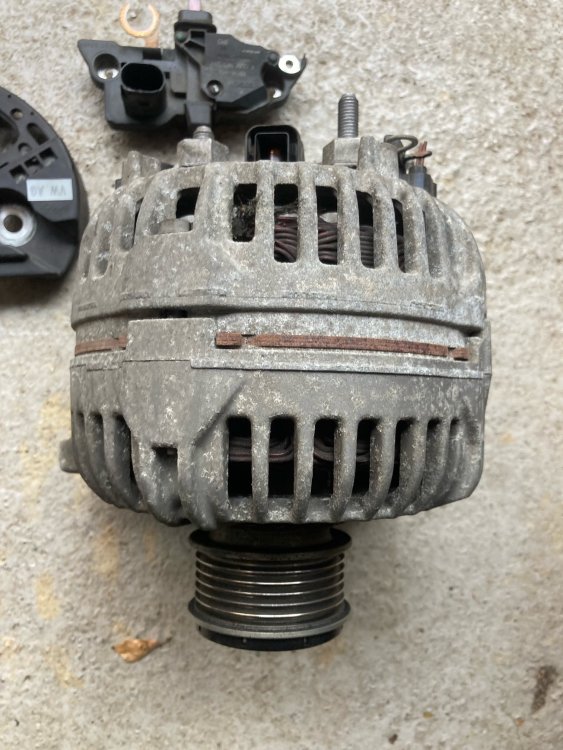
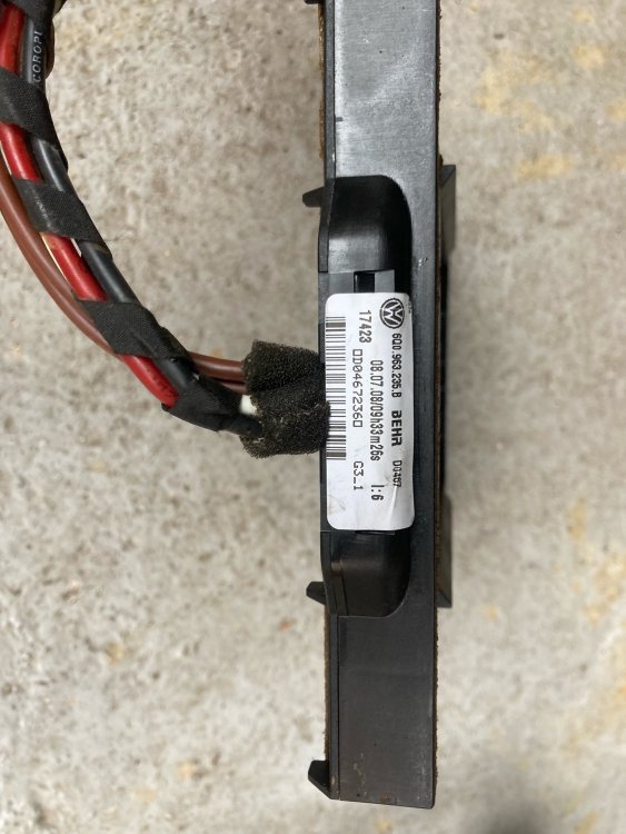
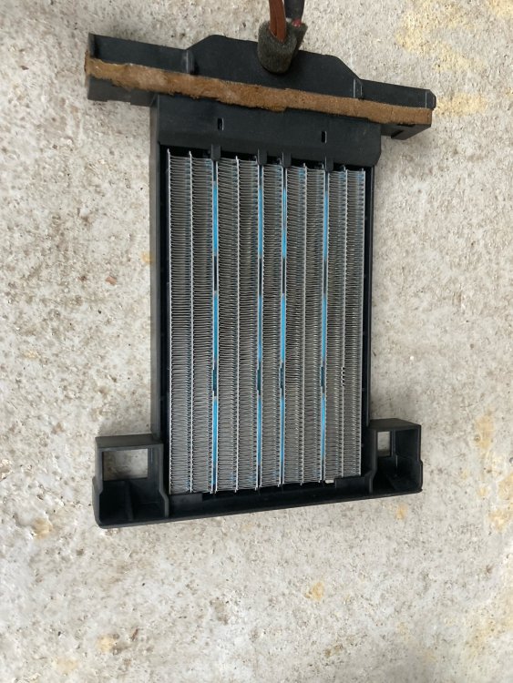
Some pictures of the various parts so far. Genuine O-rings, fuses and fuse holder, along with the connector for the PTC. The second hand alternator came and I stripped it, its from a 2007 Polo, as aside from being dirty is in pretty good condtion, lots of material left on the brushes. There are some pictures of the PTC and associated lower covering too. You can see the brown residue where there was once foam tape, and its location is why I wanted something fire retardent.


-
Yeah its the best I've seen for a while. Other projects of mine I've used TE for help identifying pins and connectors. They're barred from releasing some information because of NDA but they're very, very helpful up to that point, even if you say you're just doing one off work with no commerical interest. Any PTC has arrived and looks really good, was nicely packed and all elements show continuity which is good. I'm getting some Xpanda expanding foam tape to replace the disengrated stuff in various areas. Seems promising and is fire rated which makes me feel more comfortable using it around the PTC. Will report back if its any good
-
Courtesy of Szymon from Polo.blue, very handy. Actually has the SIKO 1 terminals listed, but they're not really possible to buy in sane quanities: https://www.a4-freunde.com/showwiki.php?title=Pins+und+alles+was+dazu+gehoert&s=058c034889a10e0ca5c7307ce9a4ef45&page=2
-
Yeah that's always an option, I'm just really curious.. Success!! N103 196 01 is Lear Corporation SIKO 1 6,3 series, with the part number of 3202557S2. Catalog here, the legacy part number is: 26817.213.178 https://www.mouser.com/catalog/specsheets/Lear Catalog.pdf I'm totally lost why they used such an odd terminal, but that is definetly it. Available here: https://www.autokabel.cz/kontakt-siko1
-
If it turns out I can't get the pins, I might take a bet on getting the pins from TE. Delphi made the harnesses in the Fabia, but they used also exclusively TE/Tyco pins and connector housings. One of the few bits on the car where Delphi used there own pins are these relay holders (large pins are 100% Delphi Ducon, the medium pins discussed above are possibly delphi, the small pins and TE Timer). As everything else is designed by TE, I wouldn't be surprised if the relay holder was too, meaning they would have most likely designed to fit both TE and Delphi terminals (evidenced by the use of TE Timer pins for the small connections). Looking at the MCP and MCON series from TE, they look very similar to Delphi Ducon and I'm fairly sure they would fit. The mystery pins I suspect might actually take a standard style spade terminal, or worst case a semi locking terminal like the Aptiv M/P shown above. It's an option at least if I can't source the actual pins from the dealer. Apologies, I know talking about pins isn't the most exciting topic for everyone, but hopefully it's a nice bit of information gathering
-
Cheers, yeah the dealer said about the A part number not existing. Its just a colour difference as far as I can tell so no worires. That's frustrating, but very helpful though thank you! 000 979 144 / 000 979 144 E (different temperature rating) seems like as close as I'm going to get. 1.0mm2. Do you know if VAG sell just the pins? N 103 197 01 is meant to be just a pin part number
-
From what I can find, 644 and 645 are the "real" relays. And they are different, 644 is green and has 2-off 9.3 mm and 2 of 6.3 mm (so fits in that socket). 645 is just a standard relay with 4-off 6.3mm terminals as you mention, and the factory install uses a different socket for each one. The 4-off 6.3mm sockets use Power time/ JPT pins so very easy to get pins for, but they obviously can't take the large pin relays.
-
Thanks very much! I actually ordered the relays earlier today otherwise those would have been handy
-
Cheers @varooom, mainly interested if they do a smaller cable size. Well I know they do, but I wonder if its actually purcasheable. Yeah I've seen those ones, they are the correct type but again they only go down to 1.5mm2 wire, wheras the ones on the car currently are definetly 0.5mm2. The 9.5 mm terminals are "easy" to get really, they're Delphi/Aptiv Ducon connectors. Its just these 6.3mm ones, they seem totally unique. Normally all the VAG stuff is TE group or Delphi, but these are neither of those. I've found two other people who've tried to identify them in the past but failed. I think I could probably make an Aptiv M/P or 56 work, but they're a bit harder to get, and obviously not the right ones.
-
To answer my own question, I think they're 000 979 236, with the pin N 103 197 01. I can find information on the former, but basically nothing on the latter.What's odd is that it seems like you can only get 2.5mm2, even though from the factory those positions normally have 0.5mm2 wire
-
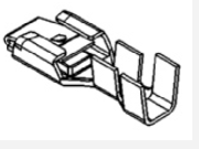
@varooomsorry to be pain but could you check something on ETKA for me? The repair wires for the "medium" pins of 4B0937527/4B0937527A (3 and 4 of the picture in the last post). If you could get a picture of them that would be great, and if not just the part number would be a start
-
This is also a dash out job, You could maybe do it with the dash in, but it would be very hard to route the wires almost impossible/impossible to connect to the bulkhead where you need to (same place as cruise control but you need to connect a large power wire too). It takes a couple of hours and is far less scary than people assume, definely easier than struggling to do it with the dash in, in my opinion.