Bete Noir
FREEDOM
-
Joined
-
Last visited
-
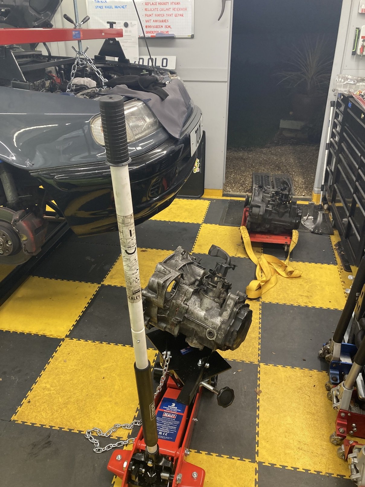
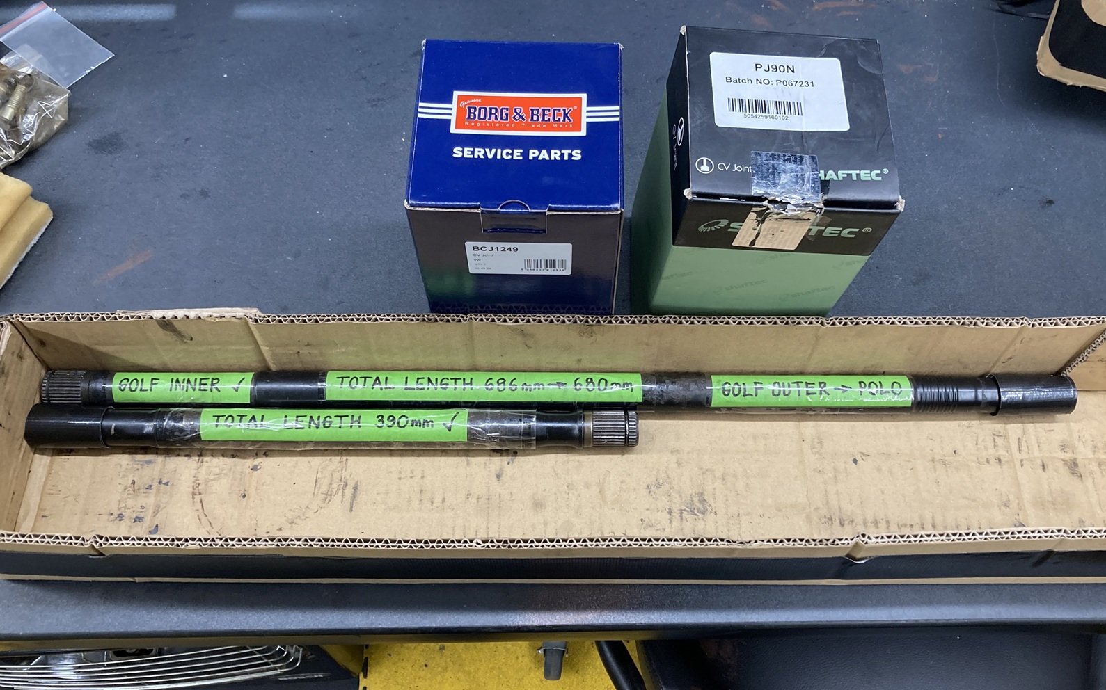
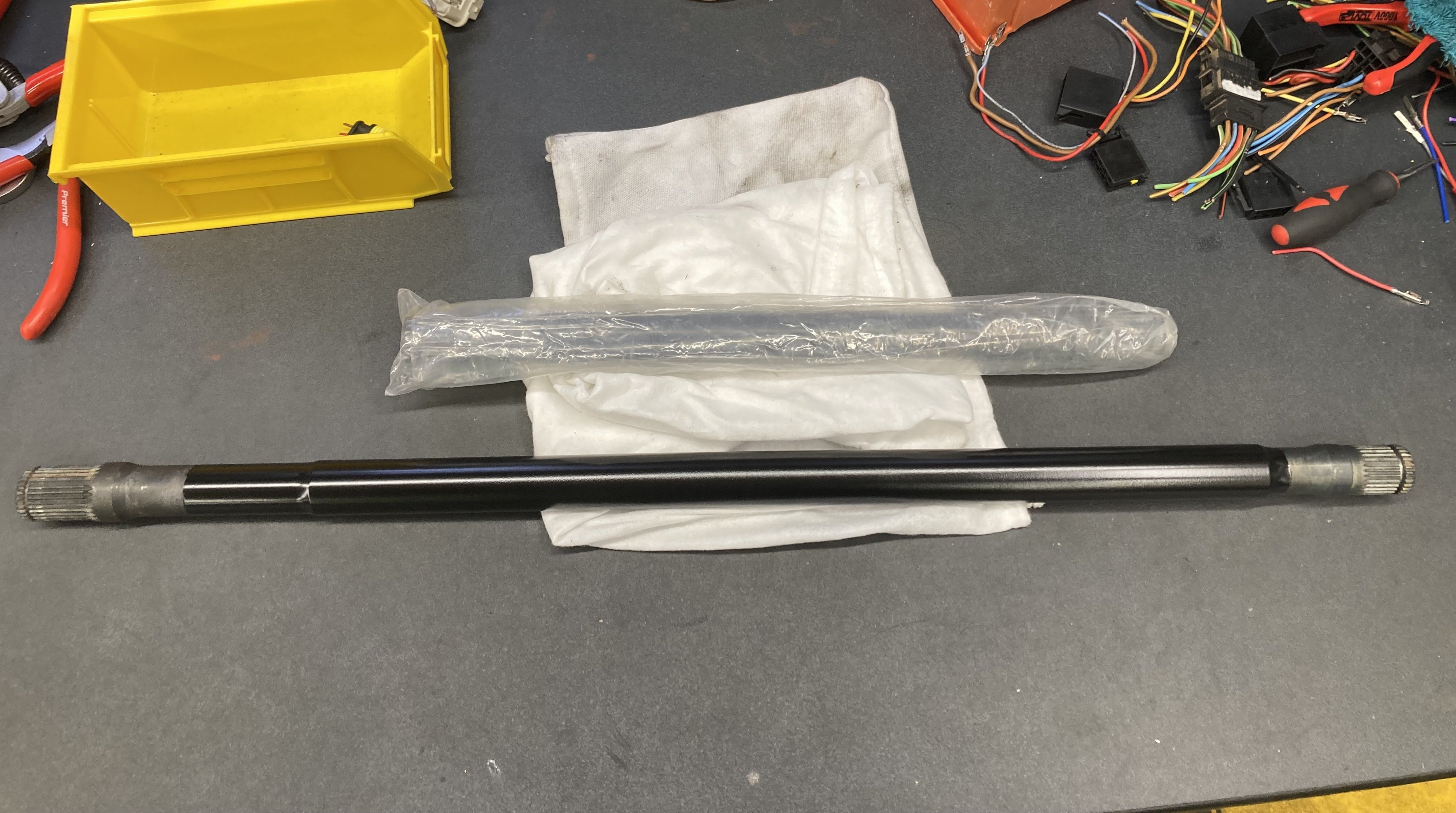
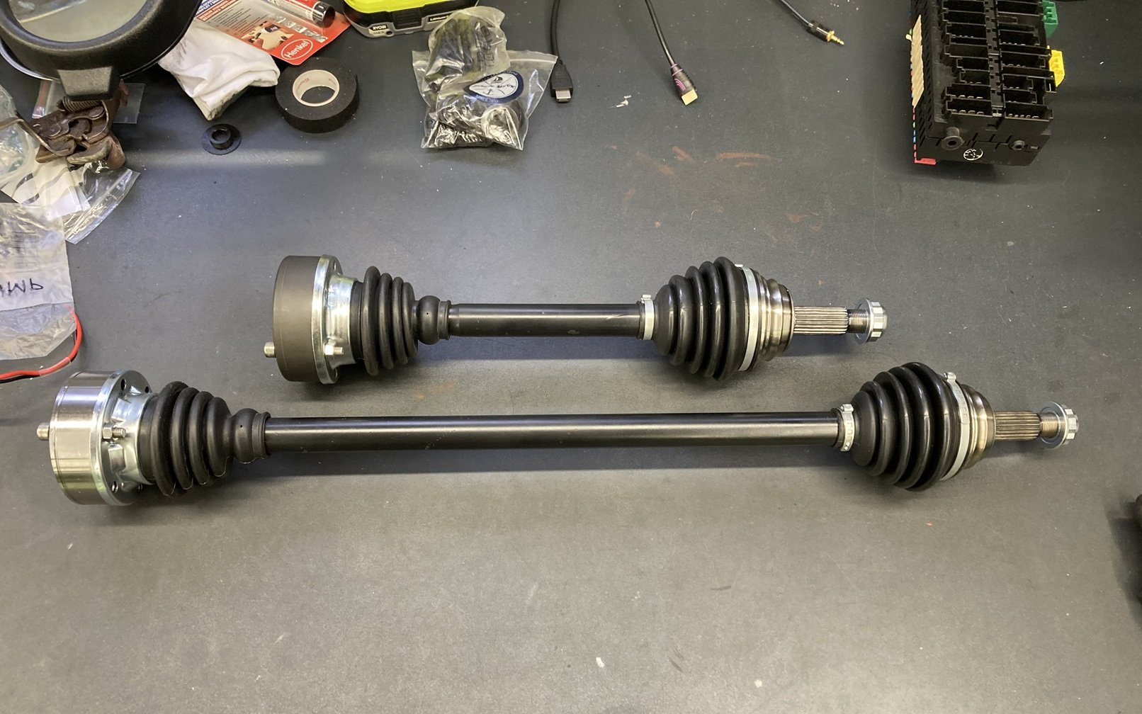
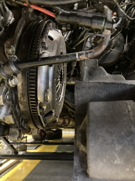
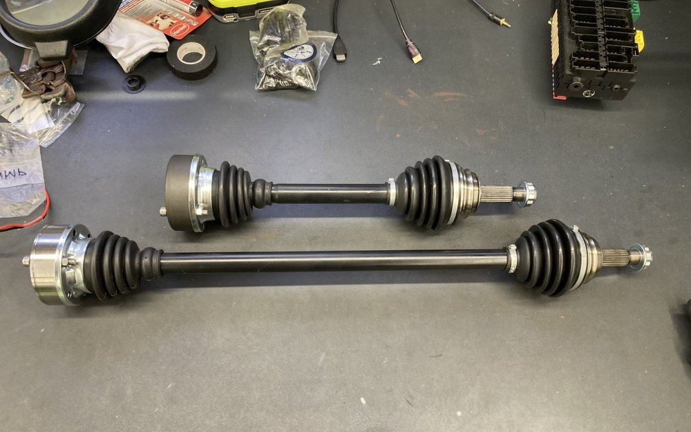
The Caddy’s gearbox had been suffering from a slight oil leak for a while. As it is not used for significant mileage, and the rate of oil loss was so low, sorting it had been on my to do list for a long time without getting anywhere near the top of that list. When I discovered that one of the driveshafts was badly worn, the silver lining in that cloud had to be that I could sort the gearbox out. I have lost count of the number of times I have had the gearbox out of this Caddy since the transplant was done, although a check back though this thread would say that I am probably sitting at four or five times. On each of the previous occasions I have used my A-frame and hoist out on the driveway, but this time I was in the workshop, and using a transmission cradle on a trolley jack. The gearbox came out readily enough. One advantage of doing the job a number of times is that I am fairly efficient at it now. Rather than making any intelligent attempt to resolve the oil leak in that box, I was swapping it for another of the same spec. I have no real idea if the replacement box is any good, but fitting it and trying it on the road will certainly confirm either way. The leaky gearbox will be rebuilt at some point for future use. With the gearbox out of the way, I fitted an ABF flywheel to replace the TDi one, so I could use a nice new VR6 clutch. After my previous flywheel / clutch nightmare I bolted them together on the bench to confirm I had the right combination, before I fitted them to the pick-up. It may be that there is a technique which I am yet to master, but I did not find it easy to fit the replacement gearbox using the cradle on a trolley jack. After the above photo was taken I added some studding side rails to the cradle, and chained the gearbox loosely to it. That enabled me to offer it up to the engine at the required angle, and then manoeuvre it into place. Seeing it written like that makes it sound much easier than it was in practice. I was dreading having to specify the driveshafts. The build thread for the Felicia 1.8T which became the donor for this Caddy did have information about the driveshafts, but it was quite difficult to follow and some of it appeared to be inconsistent. That in combination with custom driveshafts not being cheap, and being scrap if I specified them incorrectly, had me fretting. I should explain that while I could have asked the supplier to simply copy the old driveshafts, one end of each shaft was not quite right, and the longer (offside) shaft when assembled was fractionally too long. After procrastination that was annoying even me, I worked-out the changes that I needed relative to the existing driveshafts, and labelled them ready to be sent off. Of the six companies I identified who may be able to make my driveshafts, just two came back with an affirmative response and an affordable price. I would have been equally happy to order from either of them, but I chose one, couriered the old driveshafts to them, and got the new ones six weeks later exactly as promised. It only occurred to me after they were ordered that the required driveshafts have the same ends as mk2 (6K) Ibiza parts, with a Golf inner end and Polo outer, although Ibiza shafts are not the right lengths. The new shafts arrived in bare metal, so I masked the ends and sprayed them with satin black from a rattle can. I thought about trying to assemble them with new CV joints myself, but I took them to JKM instead, and I was glad I did because the joints are very tight on the shaft splines. The inner joints are both the same part number from the same manufacturer, but one of them arrived in bare metal while the other has a black finish. Since the only way to see them both when they are fitted is to be underneath the Caddy, I am going to try not to stress about the fact that they do not match. Fitting driveshafts is not a job that I enjoy. The Caddy was on a scissor lift in my workshop, which is a significant improvement on having it on axle stands on a gravel driveway, but I still find it awkward, despite having done it many times. Maybe one day I will discover the knack I have been missing. Despite my trepidation, the nearside (shorter) shaft went on a treat, and then the offside shaft looked set to do the same. Both sides were bolted to the gearbox output flanges, which is the part of the job I like least, and the driveshaft hub nuts were on finger tight. All that remained was to torque these nuts, then stand back and admire my work. The nearside hub nut had read the script, and torqued-up without difficulty. Things were different on the offside. These nuts have to be very tight, and the offside one was close but not at the required torque when it suddenly went loose. This could be very bad news. The nut was now spinning freely, but was not moving on the CV joint thread in either direction. Apparently I had stripped the thread on the CV joint or the nut or both. For the avoidance of doubt, I had been using a torque wrench to tighten the nut, I had not been attacking it with an impact gun (yet). After a brief interlude of quiet contemplation (plus some swearing and a bit of panic) I realised the only way to resolve this required the driveshaft to come off again, so I got back underneath and unbolted the inner end. With the weight of the driveshaft supported on a bungee I (now) got the impact gun onto the hub nut whilst pulling the shaft away from the hub to get the nut to bite on the thread. This worked a treat, so I soon had the driveshaft on the workbench to inspect the damage. The thread inside the nut was a mess. This was a brand new nut which was supplied with the brand new CV joint it had been wound onto, and it had definitely not been cross-threaded. I suspect that it was a material rather than a manufacturing fault, which caused the thread to strip from the nut once it started to get tight. The thread on the CV joint, which was much more of a concern, had not escaped unscathed, but looked salvageable. Once I got it under the magnifier I could see that most of the apparent damage to this thread was where detached bits of the thread from the nut had lodged themselves on the shaft. I spent more than an hour carefully removing this swarf and cleaning the thread, until eventually I could wind a nut on and off the whole length without resistance. This was one potential set-back avoided. There was still another nagging doubt to be sorted. Was the problem with tightening the hub nut caused by me having specified the driveshaft incorrectly? This seemed unlikely to the point of being hard to see how it could, but until it was fitted to my satisfaction I could not completely dispel the doubt. So I shuffled underneath the Caddy again and bolted the inner CV joint back to the gearbox, then fitted another new nut to the end. This time it tightened just fine. I still need to drive the Caddy on the road to be 100% certain that its new driveshafts are good, but all the signs up to this point are positive, for which I am very relieved.


-
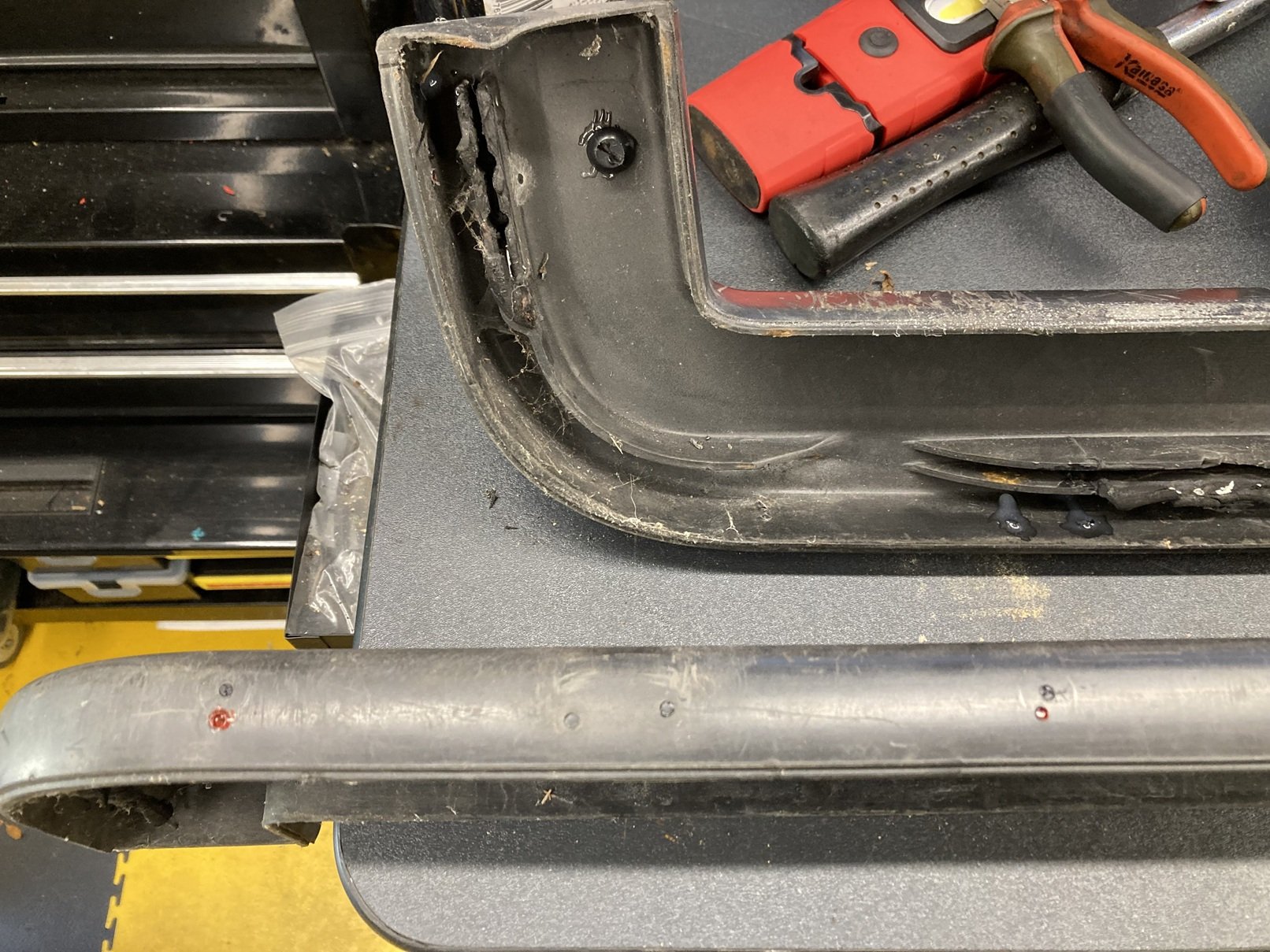
@skoda_cat When I bought this pick-up it had a checkerplate load cover which was hinged to the square section tube under the back edge of the remaining bit of checkerplate. I removed the load cover years ago, but I left that bit in place just because I thought I might replace the cover at some point. That is now vanishingly unlikely, but the bit that is still there does not get in the way, and adds a bit of extra rigidity to the rear bodywork, so I decided to keep it.
-
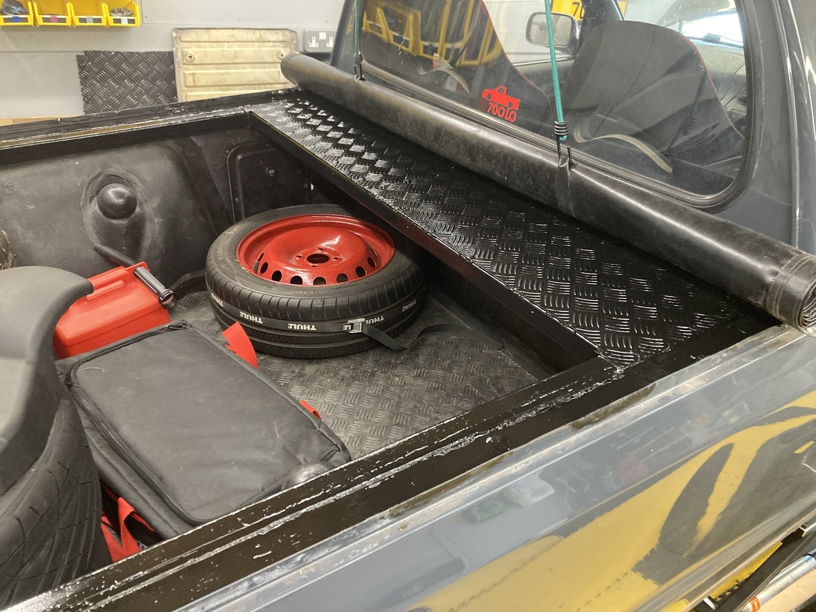
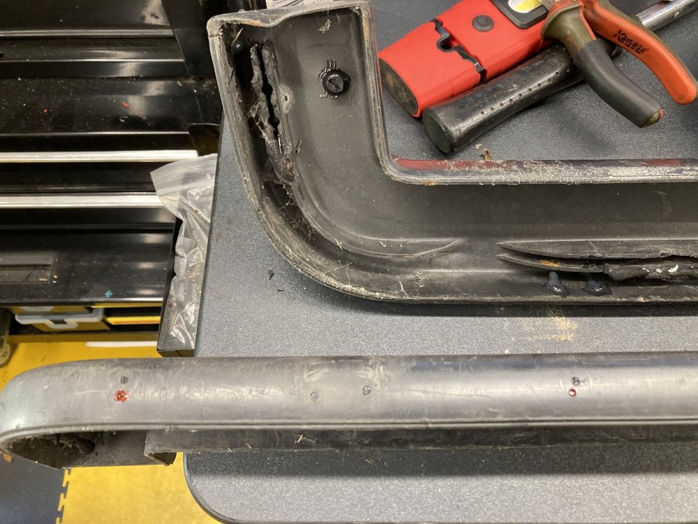
It has been a long time since I have updated this thread. My Caddy has not been forgotten, but it has largely been abandoned in favour of my Ibiza project (the SEAT variety, not a Balearic housing development). The Ibiza is now finally MOTed and in use, so I can turn some attention back to the Caddy. The pick-up has been enjoying the comforts of my garage workshop for a while because it is far from watertight. If it is parked out in the rain, both the passenger side footwell and the rear load bed fill with water. The windscreen seal is the obvious suspect for the wet carpet in the cab, on which more later, but the route for the water to get into the back was less obvious, given that it is rarely left without the tonneau cover in place. Suspicion fell on the front corners of the load area, where the ‘hockey stick’ top trims had been cut to finish more or less level with the cab back rather than extending across the B-pillar as standard. This appeared to have left a route for the water to get past the end of the trims and into the back, which warranted further investigation. Neither the side nor the rear top trims had ever been fitted particularly well in place. With the side pieces I had resorted to putting a couple of rivnuts in the top of each body side and screwing the trims down, which kept them in situ but was pretty unsatisfactory. The trim at the top of the tailgate had always sat high at the offside end, and whilst it did not obviously contribute to the water ingress it was worth looking at whilst the sides were being addressed. When I removed the tailgate top trim I discovered that the flange on the tailgate onto which it slots was folded over at the offside end, which was preventing the trim from sitting properly in place, and the captive bolt at that end was absent from its (broken) mounting, suggesting that possibly a previous owner had over-tightened the nut in an attempt to overcome the obstruction caused by the fold in the flange. I had a couple of used spare sets of trims in the shed, which were complete (as in not obviously broken or butchered) although not great cosmetically, so I selected the best set to trial fit. It became immediately apparent that the trimmed shape at the front of the side trims had masked the fact that they had not been located properly. I located the front of the trims onto their mounting flanges, then gave them each a couple of gentle taps with a rubber mallet on the rear corner to position them flush against the cab back before applying the mallet all along the top to ease them down to where they are supposed to be. The original parts had never fitted so well, and the gap at the front corner is no more. The folded mounting flange at the top of the tailgate was easily rectified via judicious use of a set of mole grips, after which the replacement trim sat neatly where it is supposed to. Now I knew the spare set would fit properly, I could turn my attention to the aesthetics. When I fitted the non-standard tonneau, I located the press studs on the top trims by progressively pulling the tonneau into position and drilling a hole for a stud so it lined-up with the other half of the fastener on the cover. It was not a massively professional (or patient) method, although the end result had looked OK. With the trims off the Caddy, however, it was clear that the press studs were neither particularly well aligned nor exactly evenly spaced. Now I decided to do better. I applied some masking tape to the outside face of each of the trims, and marked a straight line for the studs to follow at the correct depth for the tonneau to fit snugly. With the side trims I fitted them in place temporarily to give a location for the front press stud, then marked locations for the others at even intervals along the line. For the tailgate trim I measured out from the centre to the required locations for the end studs, then marked the others at even intervals in-between. Once I had drilled all of the new holes, only two of which corresponded with existing holes in the trims, I marked them all with red paint to show which were the ‘right’ ones, as the trims now had a lot of holes in them. The trims I had chosen to use had at some stage had the ‘goalpost’ style mountings for an original tonneau, and subsequently had another set of holes for press studs. All of these ‘extra’ holes would be invisible with the tonneau in place, but I had a cunning plan to deal with them. I had used a 2.5mm bit to drill the new holes, and I realised that I had some black plastic drive rivets which had a central shaft of very similar diameter. A trial fit confirmed that these handy little nylon cylinders were a perfect fit for most of the unwanted holes, requiring a couple of taps with a mallet to get them in place, and being nigh-on impossible to dislodge thereafter, so I set-to cutting a load of drive rivet centres in half, tapping them into place, and putting a dab of araldite on the back to be absolutely sure they would stay in place. Both replacement side trims had a small hole in the top surface by the rear corner, almost certainly where a screw had been used to keep them in place. I could not use the same technique to fill these holes, as the top surface of the trims is too thin. Instead I drilled the holes out and tapped them for M6, so that I could screw (and glue) black nylon number plate fixing screws in from the underside. Once the glue was set I trimmed the thread down to the level of the top surface of the trim. Various clamps, and judicious application of a heat gun, enabled me to correct a few places where the trims were mis-shapen, and then a bit of sanding further improved the look of the now-filled holes before priming and painting. I could have saved myself a lot of time and effort by using filler in all of the unwanted holes rather than faffing about finding bits of black plastic to glue into place, but I decided this solution would be more durable for when I am using my pick-up for its intended purpose. I do not want to have to worry about cracks appearing in the filler when things are (inevitably) dropped onto the top trims. Only time will tell whether my efforts have been worthwhile. Whilst the top trims were off, I decided to give the checkerplate ‘shelf’ and additional side rails a couple of coats of paint. I had some Hammerite black satin so that was what I used. Once the top trims are eventually back on this should have it looking much smarter in the back.

-
Thank you
-
I am planning on replacing the windscreen rubber seal on my Caddy (Felicia) pick-up. Can anyone make recommendations based on personal experience of decent quality Felicia windscreen seals vs manufacturers to be avoided?
-
Behind the NSR light unit there is a handy spare hole in the panel, intended (I think) for tow bar wiring. Run the cables through there and that gets them behind the bumper.
-
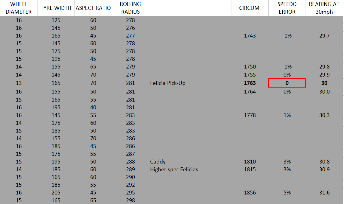
This might help on wheel and tyre sizes. It is not an exhaustive list, just something I put together when having a similar dilemma. Ignore the 'reading at 30mph' column heading, I think it should be 'actual speed when the speedo says 30mph'. Are you thinking steel or alloy wheels?

-
I am honoured to have provided some inspiration 🙂 For my Felicia I made up a SURPRISING SKODA sticker for the rear window, in the style of the 90s (?) advertising slogan. It seemed appropriate in a tired-looking Felicia hatchback running 200hp. 😆
-
Did you particularly want to use an additional (LED) indicator lamp for this? In my pick-up I have the heated rear window tell-tale in the instrument cluster wired to show me when the radiator fan is on.
-
Excellent I like it already. More details please. Is this a body / floorpan swap? (is the 60s Octavia even a monocoque?).
-
Bete Noir replied to vladimirzootin's topic in Skoda Favorit, Skoda Felicia, Skoda Fun and Skoda FormanNo it's perfectly sensible 🤪. I would definitely recommend improving handling and braking before considering more power, however.
-
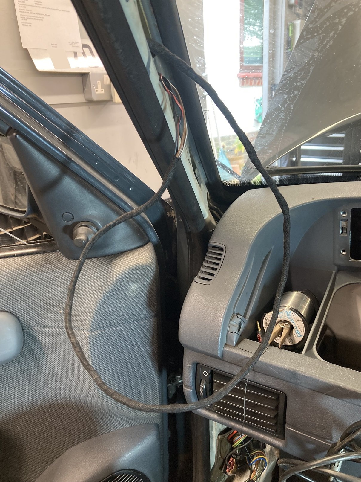
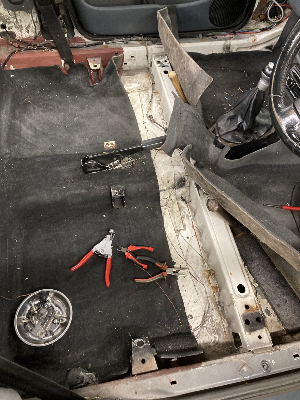
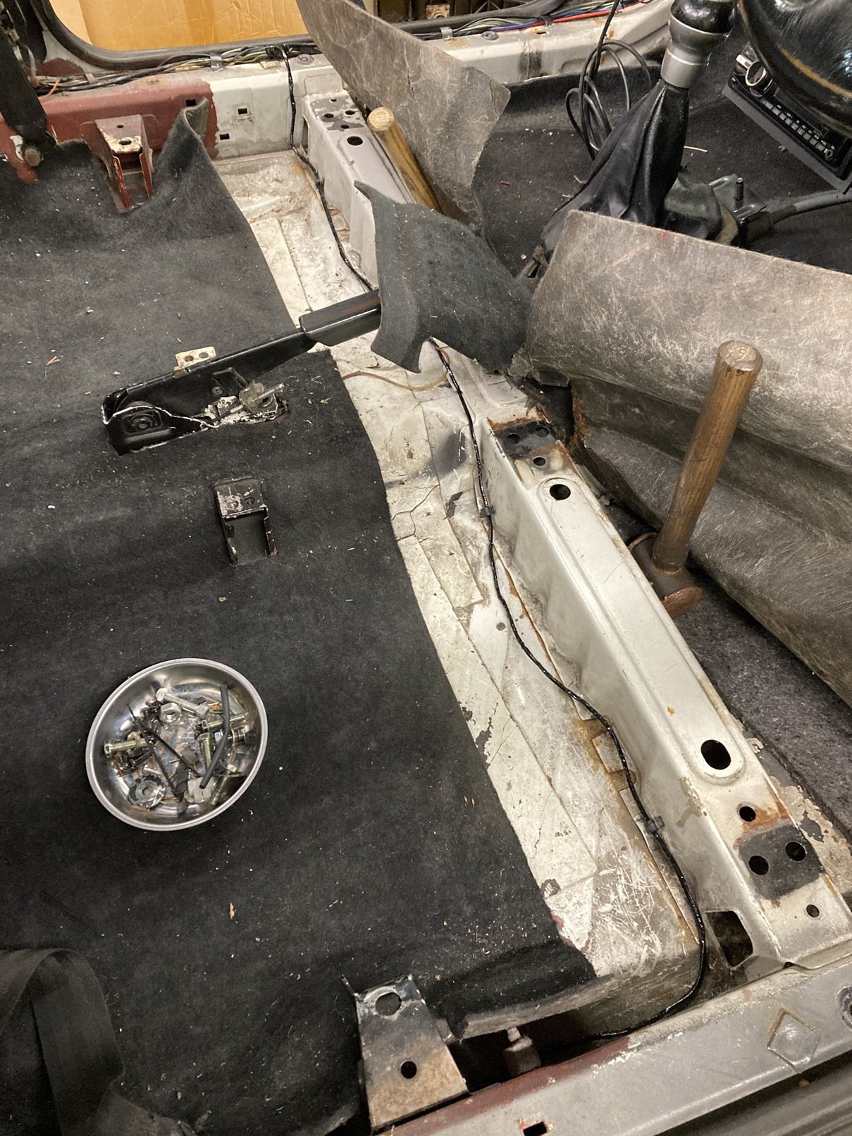
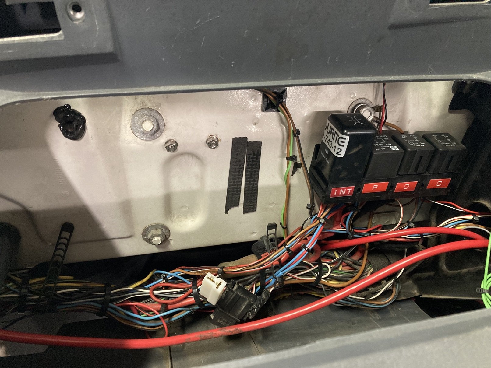
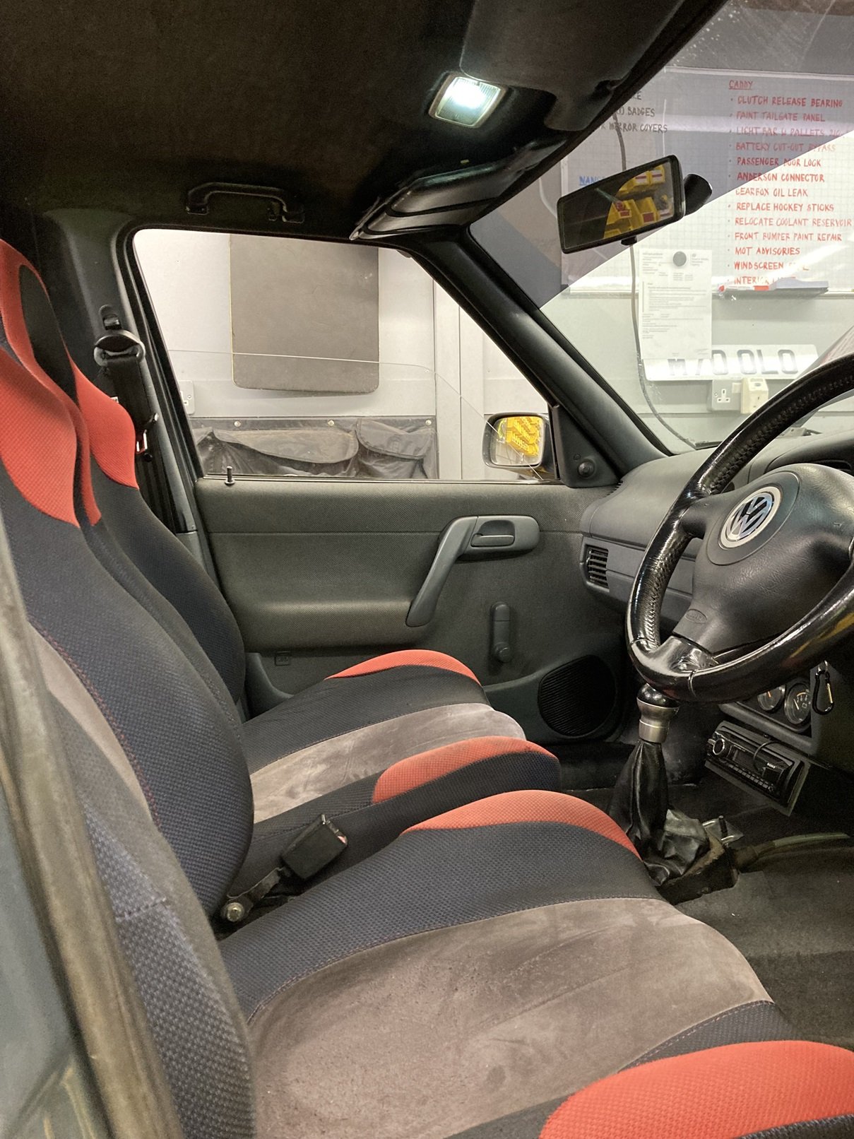
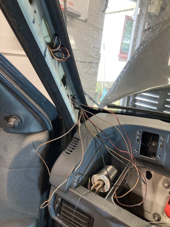
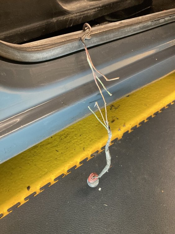
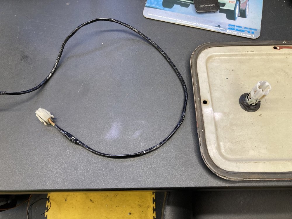
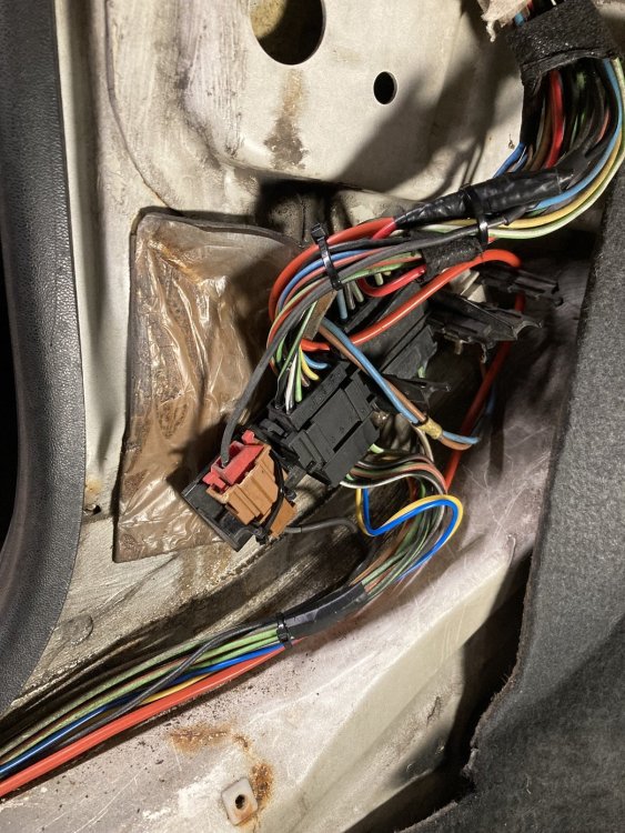
In the midst of tidying the load area top ‘hockey stick’ trims, I sat in the Caddy and noticed that the interior light was not working. Anyone who has read this thread all the way through will be aware that I like nothing better than sorting an electrical fault, and it had to be a simple fix, maybe even just a bulb, so I decided to sort it out. Little did I know what I was getting into. First I tried the easiest and most obvious fix, and replaced the bulb. There was already an LED bulb fitted, but I tried a different one. It made no difference. The next step was to take the interior light out and test it on the bench. It still refused to illuminate, so I dismantled it and cleaned all of the copper contact surfaces. After that it burst obediently into life (well light, at least) on the bench. When I then re-connected the light in the Caddy, it worked fine on the ‘manual’ setting, but remained defiantly dark when switched to operation via the door contact switches. I removed the light again and replaced it with a test LED, which was illuminating only dimly when the passenger door was open. This suggested that there was a high impedance connection between the door switches and the interior light, which was not great news. I had only just replaced the passenger side sill trim and kick panel, but I had to take them off again to access the wiring at the base of the A-pillar. A quick test at the connector there confirmed that the connection to the door switch was good, and the issue was between there and the light. I got into the loom behind the glovebox, located the wire from the door contact switches towards the interior light, and cut it at a junction where the blue wire from the A-pillar connector was crimped to a brown/white wire. The core of the brown/white wire was in a terrible state, and was a likely culprit for causing the fault. As this wire is run inside the windscreen pillar, and is wrapped within the loom of four wires going to the light this was further bad news, and I spent a while working-out how to remedy it. My solution was to take all of the slack out of this loom in the roof and behind the glovebox, so that I had enough slack within the windscreen pillar to pull a loop out through one of the holes in the pillar. Once I had removed the wrapping tape from this section of loom, which was very easy as it had deteriorated due to its age, I cut all four wires and soldered a new length of about 500mm between each of the cut sections. I staggered the cuts so that the solder joins would not make the loom significantly thicker in one place. At this point it did not look great. I was able to wrap the new section of loom and the unwrapped sections of the existing loom with coroplast tape to tidy and protect it. With this done, I could pull the loom through from behind the glovebox, so that the new section was inside the windscreen pillar, and the original section, including the damaged brown / white wire, was now accessible behind the glovebox. I could now cut out the damaged section and cut the other cables to length before re-soldering them to reinstate the circuit, but if I am repairing something I always like to upgrade it if I can, and I had already decided that this was an opportunity to do that. My plan was to add a time delay relay to the interior light. I believe that later Caddys and Felicias had a different interior light which boasted time delay functionality, and it would have been very easy to just acquire one of those lights for my Caddy, but I was keen to retain the original rocker style light. I recently fitted an interior light delay relay in my SEAT Ibiza track project, and in doing so I had learnt a few lessons (as in, made every possible error) so I expected to be able to sort the circuitry in the Caddy without too much difficulty, and so it proved. I briefly enjoyed my success at getting the interior light to switch with the passenger door opening and closing, before I twigged that I had not tried the driver’s door. When I tried it then and the light failed to operate it was not a nice surprise. It did not take long to work out why it was not working. This was the state of the wiring from the driver’s door switch. The loom had not been routed correctly, and had most likely found its way into the seat runner and been sliced by the movement of the seat. Whether or not it had happened like that, two of the three wires were completely severed. This was not particularly disheartening, as all that was needed was to cut the damaged sections of wire out and solder new ones in. The core of the brown/white wire at the cut did not look good, so I cut it back a few inches to find some good copper, and I kept doing so as each cut failed to reveal anything I could solder to. Eventually I got to this point. I had to cut the wire back all the way to the passenger side sill before I found good copper, so the new wires I soldered in were somewhat longer than I had expected. Once these new sections were in place the circuit tested successfully, so I re-wrapped the loom across beneath the seats, and clipped it into its proper place. Once I had the carpet down again, and before I re-fitted the seats, I treated the carpet to a long overdue going-over with the workshop Henry. The fasteners that had been fixing the seats into place were a varied and dubious collection, none of which looked like they belonged. I found some more suitable bolts, and even located a pair of captive nut plates for the outer rear mountings. My Caddy has Subaru seats, which are more comfortable and supportive than the standard ones, although I have a hankering for a pair of red leather Audi TT seats. I included the photo below to show that all of this work did result in a nice bright interior light. The interior light delay relay is located on the bulkhead behind the glovebox, alongside three other relays I have installed for various circuits. Whilst I was completing the interior light and relay wiring, I also spent some time tidying the rest of the wiring behind the glovebox. This included removing the frayed remnants of the loom wrapping tape, replacing a few insulated crimp connections with soldered and heatshrink sleeved joints, and then adding a few strategic cable ties to make it look a bit like a loom again. The white 2-pin plug towards the centre is for the glovebox USB socket.


-
These look like the brackets from the front of the front inner wings.
-
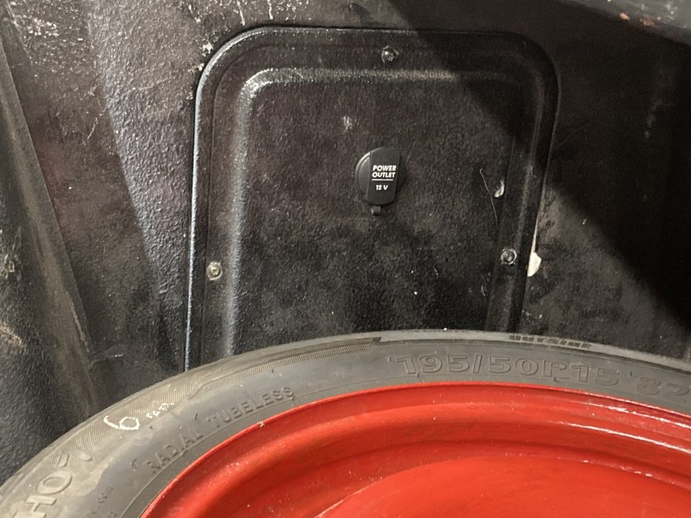
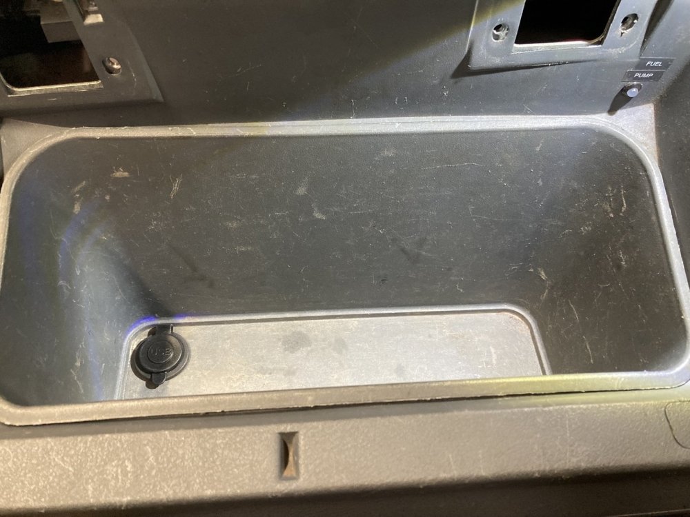
Having the sill trim off to do the wiring for the centre brake light presented a perfect opportunity to tick another job off the to do list which had been on there a long while, which was fitting a 12v socket in the load area. I removed the nearside front side access panel and cut a hole in it for the socket to fit into, then made up a new section of loom to connect to it. My Caddy has a non-standard earth connection at the base of the passenger side B-pillar, so I bolted the socket’s earth lead to that. The socket has a connection for illumination, so I connected that into the sidelight circuit, even though I cannot see why I would ever need it to be illuminated. The wire from the positive terminal was run along the top of the sill towards the fusebox, but when I got the kick panel off I spotted a 2-pin socket (the red one in the photo below) with a black wire in it, and no plug attached. I decided to investigate where this black wire is connected in the fusebox. It turns-out this is connected to fuse S15 which makes it perfect as a supply for my new load area 12v socket, so the wire from the socket was quickly fitted into a plug (the brown one) and the two were mated together. That was much easier than I thought it might be! Hardly worthy of a picture, but the socket in the load area looks to me like it belongs there. Whilst I was playing around with the 12v supply for the load area socket, I also added a USB socket in the bottom of the glovebox. This will be ideal for plugging-in the satnav, rather than using the cigarette lighter socket which puts the satnav cable sufficiently close to the gearstick that I have pulled the satnav off the dashtop more than once when changing gear. Neither the most riveting update, or very interesting pictures, but it is all part of the story 😊
-
Thanks. To be fair, the spoiler was attached to a rigid load cover which was hinged at the front, so it was out of the way when loading. It was actually like a really big handle to lift the load cover 🙂