


Bete Noir
FREEDOM
-
Joined
-
Last visited
Everything posted by Bete Noir
-
Thank you
-
I am planning on replacing the windscreen rubber seal on my Caddy (Felicia) pick-up. Can anyone make recommendations based on personal experience of decent quality Felicia windscreen seals vs manufacturers to be avoided?
-
Behind the NSR light unit there is a handy spare hole in the panel, intended (I think) for tow bar wiring. Run the cables through there and that gets them behind the bumper.
-
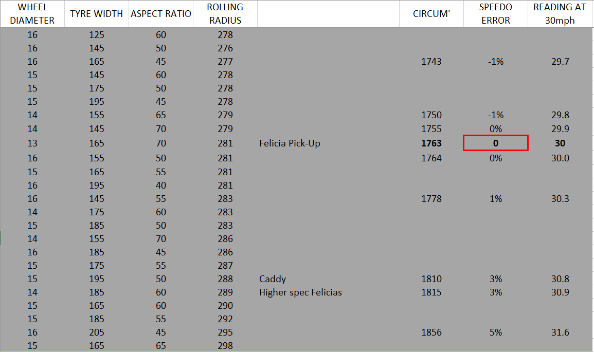
This might help on wheel and tyre sizes. It is not an exhaustive list, just something I put together when having a similar dilemma. Ignore the 'reading at 30mph' column heading, I think it should be 'actual speed when the speedo says 30mph'. Are you thinking steel or alloy wheels?

-
I am honoured to have provided some inspiration 🙂 For my Felicia I made up a SURPRISING SKODA sticker for the rear window, in the style of the 90s (?) advertising slogan. It seemed appropriate in a tired-looking Felicia hatchback running 200hp. 😆
-
Did you particularly want to use an additional (LED) indicator lamp for this? In my pick-up I have the heated rear window tell-tale in the instrument cluster wired to show me when the radiator fan is on.
-
Excellent I like it already. More details please. Is this a body / floorpan swap? (is the 60s Octavia even a monocoque?).
-
Bete Noir replied to vladimirzootin's topic in Skoda Favorit, Skoda Felicia, Skoda Fun and Skoda FormanNo it's perfectly sensible 🤪. I would definitely recommend improving handling and braking before considering more power, however.
-
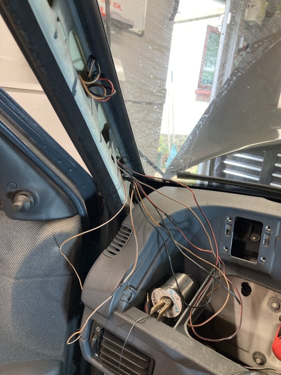
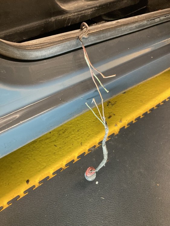
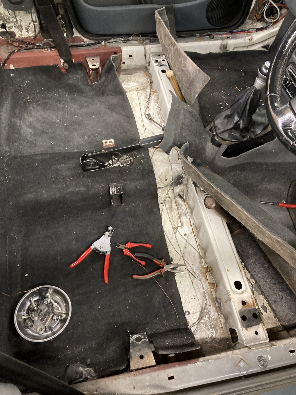
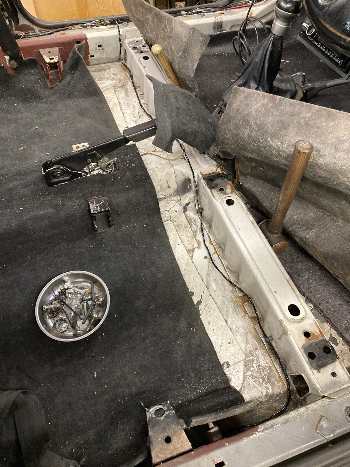
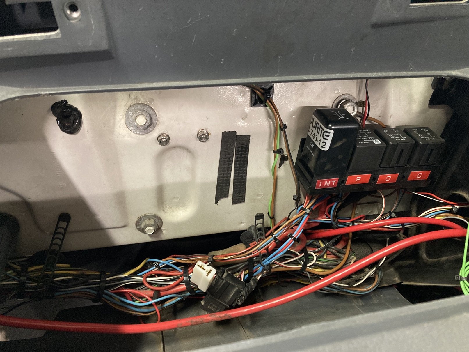
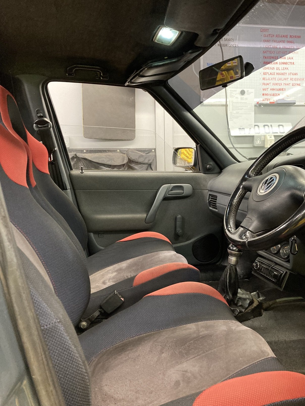
In the midst of tidying the load area top ‘hockey stick’ trims, I sat in the Caddy and noticed that the interior light was not working. Anyone who has read this thread all the way through will be aware that I like nothing better than sorting an electrical fault, and it had to be a simple fix, maybe even just a bulb, so I decided to sort it out. Little did I know what I was getting into. First I tried the easiest and most obvious fix, and replaced the bulb. There was already an LED bulb fitted, but I tried a different one. It made no difference. The next step was to take the interior light out and test it on the bench. It still refused to illuminate, so I dismantled it and cleaned all of the copper contact surfaces. After that it burst obediently into life (well light, at least) on the bench. When I then re-connected the light in the Caddy, it worked fine on the ‘manual’ setting, but remained defiantly dark when switched to operation via the door contact switches. I removed the light again and replaced it with a test LED, which was illuminating only dimly when the passenger door was open. This suggested that there was a high impedance connection between the door switches and the interior light, which was not great news. I had only just replaced the passenger side sill trim and kick panel, but I had to take them off again to access the wiring at the base of the A-pillar. A quick test at the connector there confirmed that the connection to the door switch was good, and the issue was between there and the light. I got into the loom behind the glovebox, located the wire from the door contact switches towards the interior light, and cut it at a junction where the blue wire from the A-pillar connector was crimped to a brown/white wire. The core of the brown/white wire was in a terrible state, and was a likely culprit for causing the fault. As this wire is run inside the windscreen pillar, and is wrapped within the loom of four wires going to the light this was further bad news, and I spent a while working-out how to remedy it. My solution was to take all of the slack out of this loom in the roof and behind the glovebox, so that I had enough slack within the windscreen pillar to pull a loop out through one of the holes in the pillar. Once I had removed the wrapping tape from this section of loom, which was very easy as it had deteriorated due to its age, I cut all four wires and soldered a new length of about 500mm between each of the cut sections. I staggered the cuts so that the solder joins would not make the loom significantly thicker in one place. At this point it did not look great. I was able to wrap the new section of loom and the unwrapped sections of the existing loom with coroplast tape to tidy and protect it. With this done, I could pull the loom through from behind the glovebox, so that the new section was inside the windscreen pillar, and the original section, including the damaged brown / white wire, was now accessible behind the glovebox. I could now cut out the damaged section and cut the other cables to length before re-soldering them to reinstate the circuit, but if I am repairing something I always like to upgrade it if I can, and I had already decided that this was an opportunity to do that. My plan was to add a time delay relay to the interior light. I believe that later Caddys and Felicias had a different interior light which boasted time delay functionality, and it would have been very easy to just acquire one of those lights for my Caddy, but I was keen to retain the original rocker style light. I recently fitted an interior light delay relay in my SEAT Ibiza track project, and in doing so I had learnt a few lessons (as in, made every possible error) so I expected to be able to sort the circuitry in the Caddy without too much difficulty, and so it proved. I briefly enjoyed my success at getting the interior light to switch with the passenger door opening and closing, before I twigged that I had not tried the driver’s door. When I tried it then and the light failed to operate it was not a nice surprise. It did not take long to work out why it was not working. This was the state of the wiring from the driver’s door switch. The loom had not been routed correctly, and had most likely found its way into the seat runner and been sliced by the movement of the seat. Whether or not it had happened like that, two of the three wires were completely severed. This was not particularly disheartening, as all that was needed was to cut the damaged sections of wire out and solder new ones in. The core of the brown/white wire at the cut did not look good, so I cut it back a few inches to find some good copper, and I kept doing so as each cut failed to reveal anything I could solder to. Eventually I got to this point. I had to cut the wire back all the way to the passenger side sill before I found good copper, so the new wires I soldered in were somewhat longer than I had expected. Once these new sections were in place the circuit tested successfully, so I re-wrapped the loom across beneath the seats, and clipped it into its proper place. Once I had the carpet down again, and before I re-fitted the seats, I treated the carpet to a long overdue going-over with the workshop Henry. The fasteners that had been fixing the seats into place were a varied and dubious collection, none of which looked like they belonged. I found some more suitable bolts, and even located a pair of captive nut plates for the outer rear mountings. My Caddy has Subaru seats, which are more comfortable and supportive than the standard ones, although I have a hankering for a pair of red leather Audi TT seats. I included the photo below to show that all of this work did result in a nice bright interior light. The interior light delay relay is located on the bulkhead behind the glovebox, alongside three other relays I have installed for various circuits. Whilst I was completing the interior light and relay wiring, I also spent some time tidying the rest of the wiring behind the glovebox. This included removing the frayed remnants of the loom wrapping tape, replacing a few insulated crimp connections with soldered and heatshrink sleeved joints, and then adding a few strategic cable ties to make it look a bit like a loom again. The white 2-pin plug towards the centre is for the glovebox USB socket.


-
These look like the brackets from the front of the front inner wings.
-
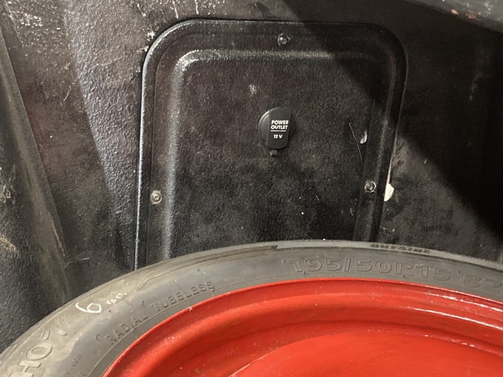
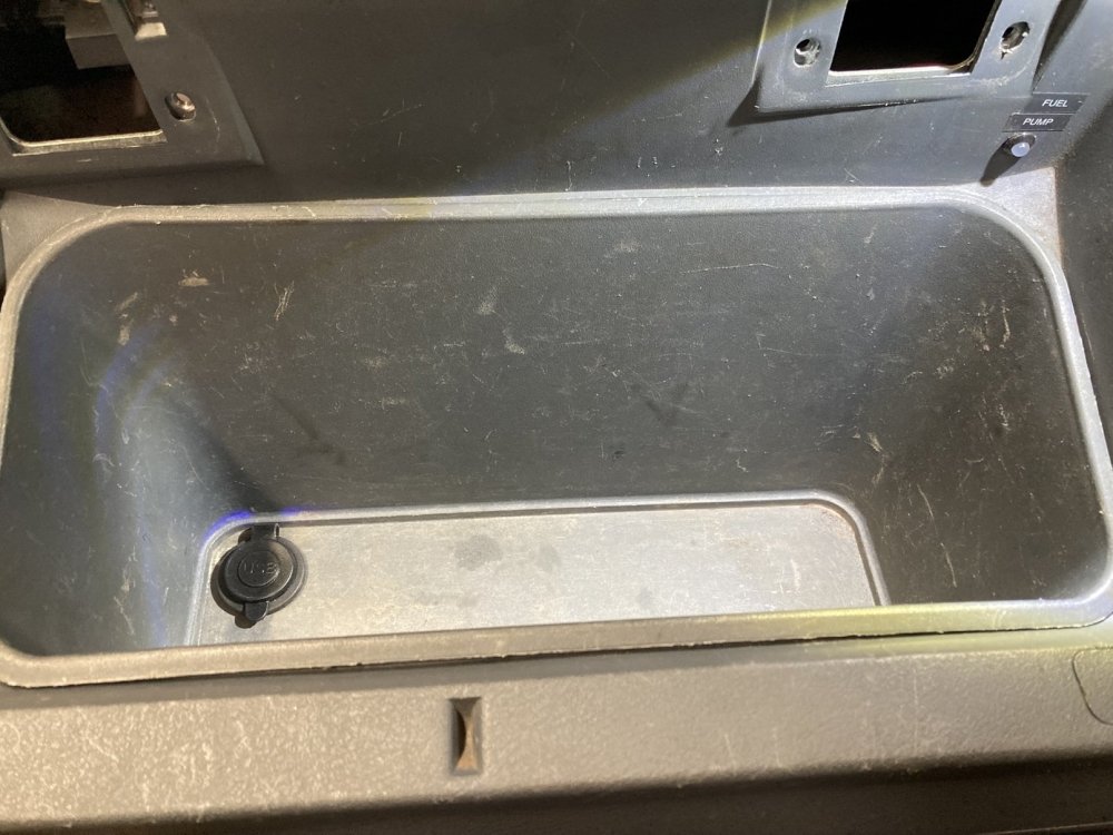
Having the sill trim off to do the wiring for the centre brake light presented a perfect opportunity to tick another job off the to do list which had been on there a long while, which was fitting a 12v socket in the load area. I removed the nearside front side access panel and cut a hole in it for the socket to fit into, then made up a new section of loom to connect to it. My Caddy has a non-standard earth connection at the base of the passenger side B-pillar, so I bolted the socket’s earth lead to that. The socket has a connection for illumination, so I connected that into the sidelight circuit, even though I cannot see why I would ever need it to be illuminated. The wire from the positive terminal was run along the top of the sill towards the fusebox, but when I got the kick panel off I spotted a 2-pin socket (the red one in the photo below) with a black wire in it, and no plug attached. I decided to investigate where this black wire is connected in the fusebox. It turns-out this is connected to fuse S15 which makes it perfect as a supply for my new load area 12v socket, so the wire from the socket was quickly fitted into a plug (the brown one) and the two were mated together. That was much easier than I thought it might be! Hardly worthy of a picture, but the socket in the load area looks to me like it belongs there. Whilst I was playing around with the 12v supply for the load area socket, I also added a USB socket in the bottom of the glovebox. This will be ideal for plugging-in the satnav, rather than using the cigarette lighter socket which puts the satnav cable sufficiently close to the gearstick that I have pulled the satnav off the dashtop more than once when changing gear. Neither the most riveting update, or very interesting pictures, but it is all part of the story 😊
-
Thanks. To be fair, the spoiler was attached to a rigid load cover which was hinged at the front, so it was out of the way when loading. It was actually like a really big handle to lift the load cover 🙂
-
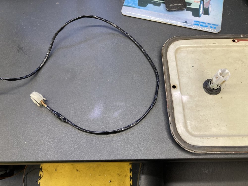
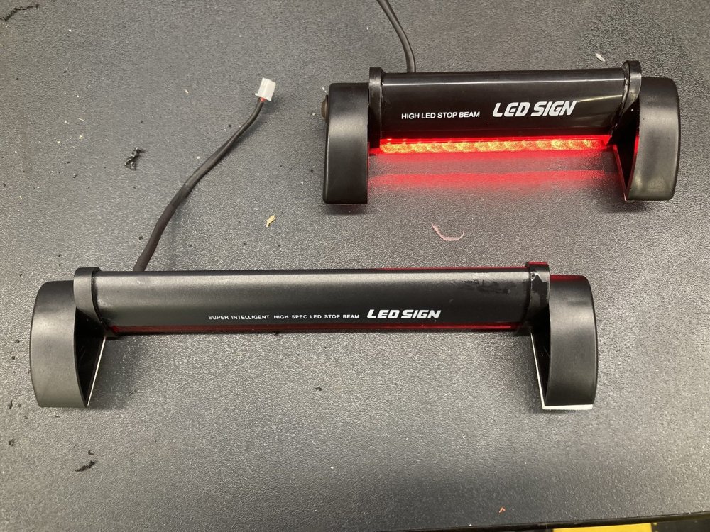
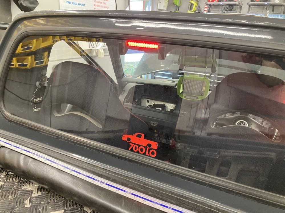
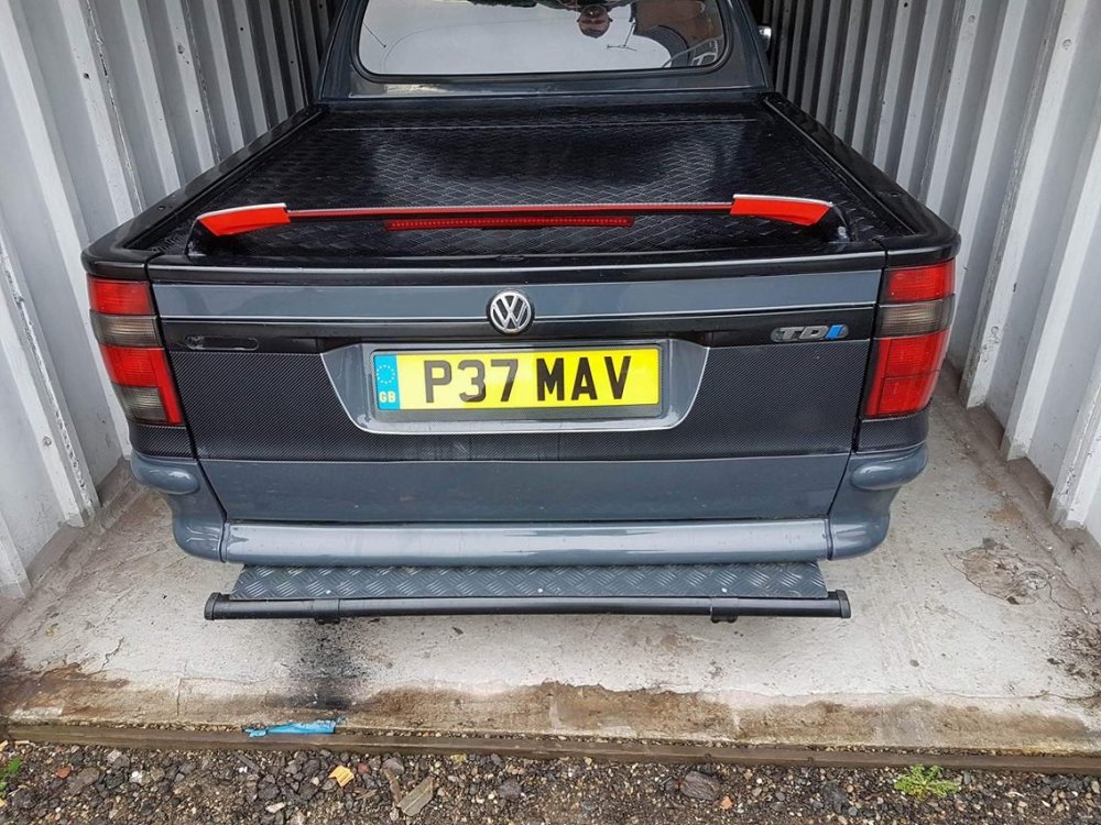
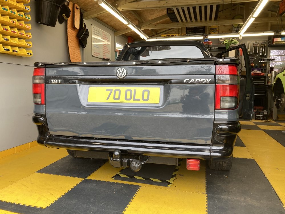
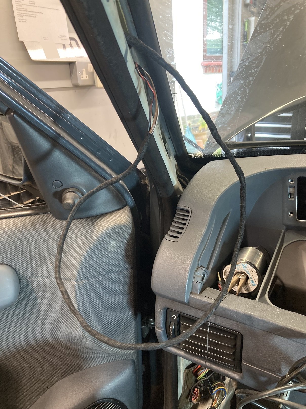
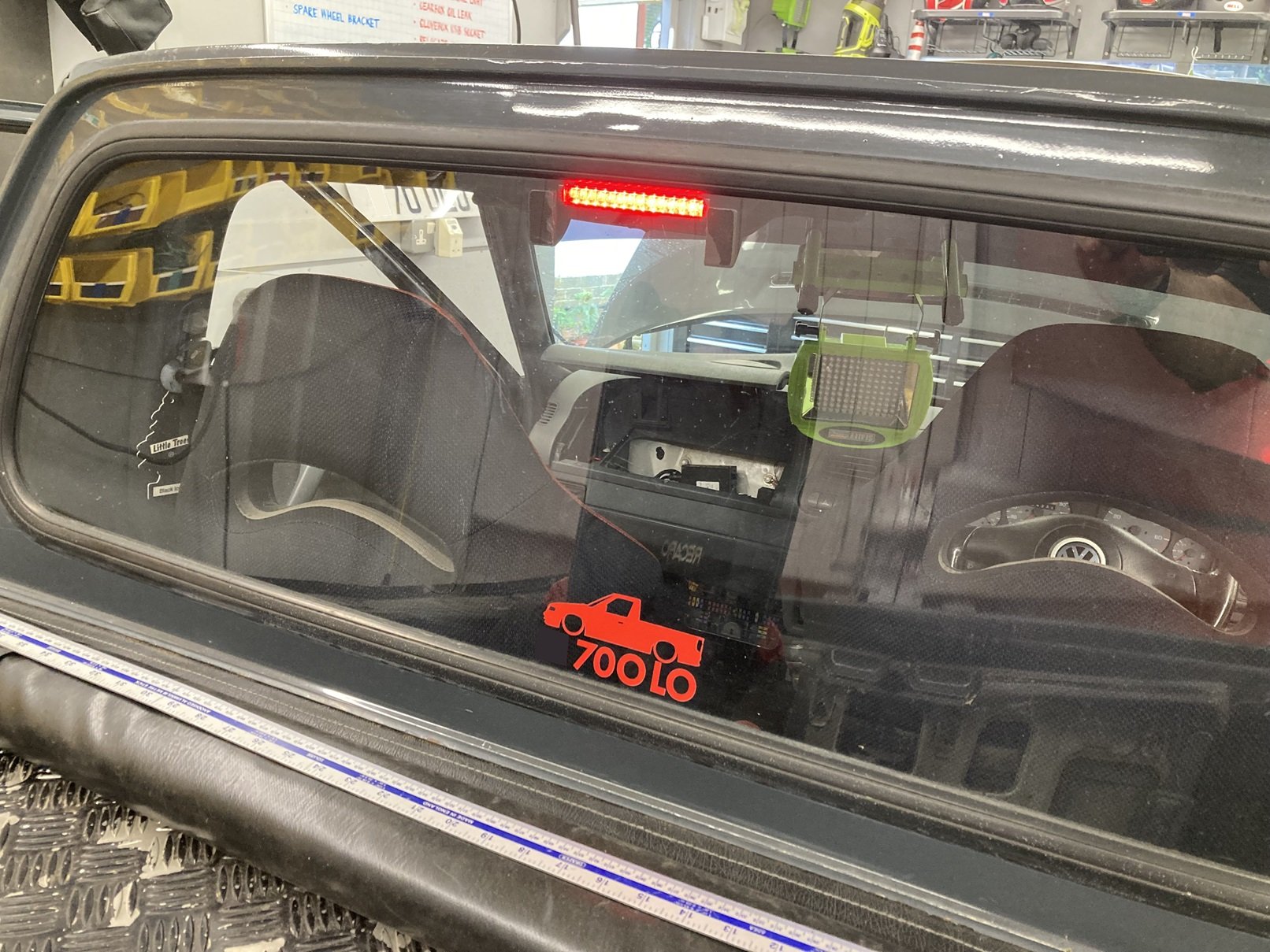
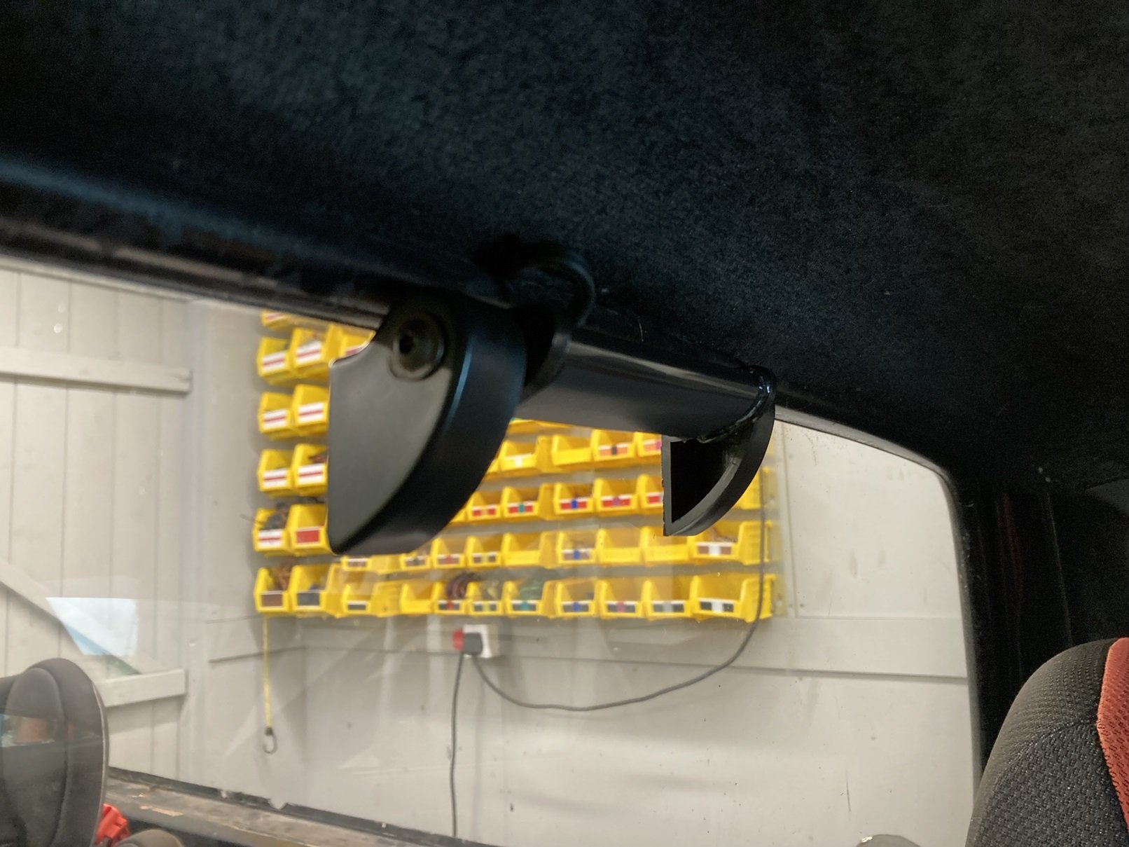
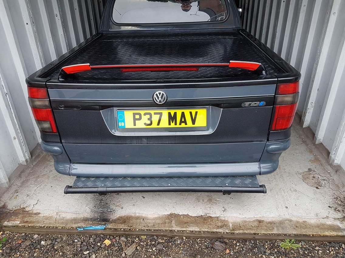
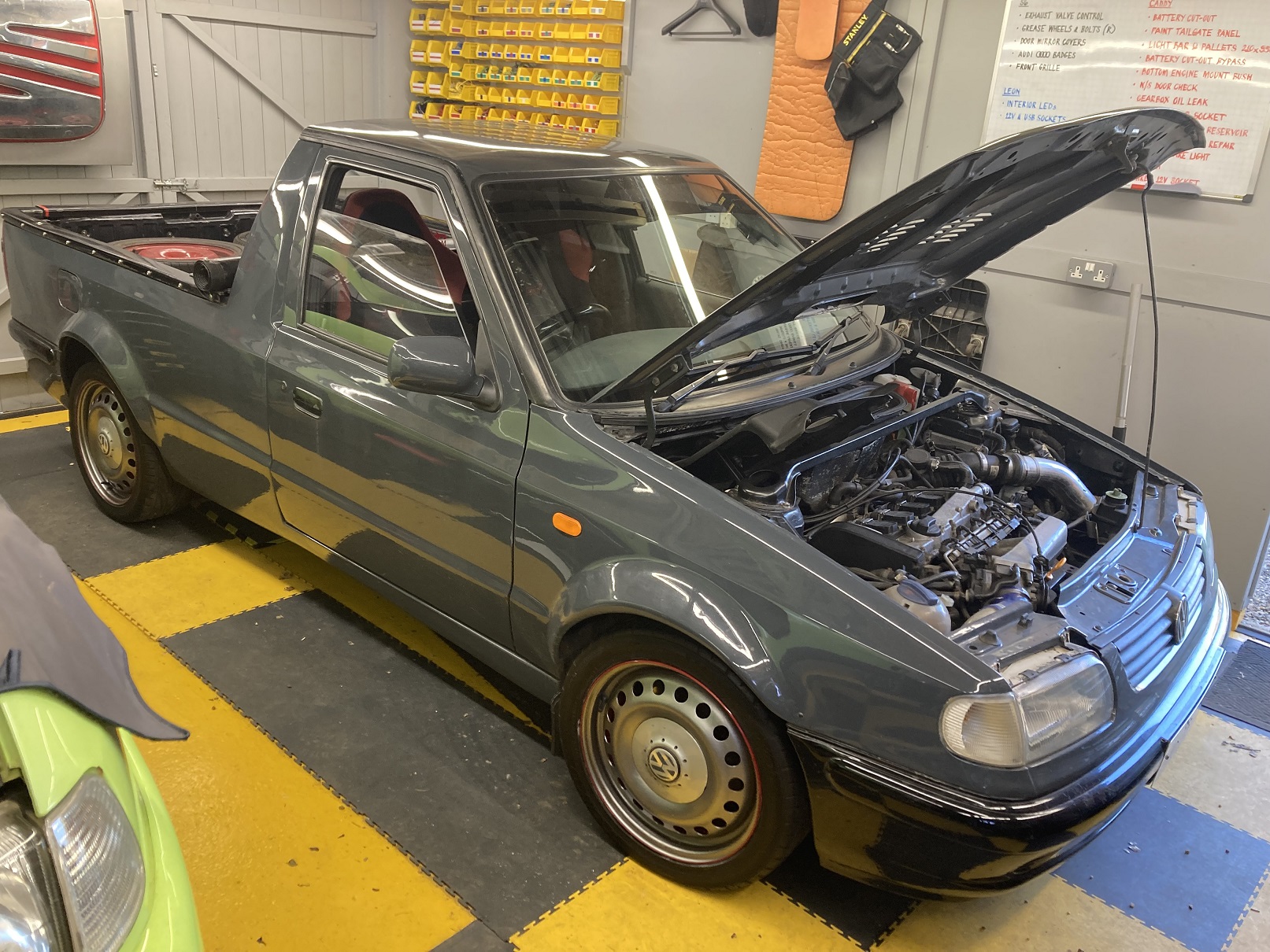
I have obviously made modifications to the Caddy to enhance its performance, and others to change the aesthetics, but I am struggling to think of one previously that has specifically been made with road safety in mind, although I have an example now. I think it is also the first instance of my reinstating a modification that had been in place when I bought the Caddy and which I had subsequently removed. My son had been driving behind the Caddy and told me afterwards that the brake lights were not as noticeable as they ought to be, in the absence of a high level centre brake light. Given that he knows that the Caddy has no centre brake light and was therefore conscious to keep an eye out, this made me think that less switched-on drivers could miss my braking altogether, with disastrous consequences. I liked the idea of mounting a brake light externally above the rear window, except that would mean drilling holes in the cab back, which I did not fancy much. I thought it would be much easier to find a universal brake light to stick inside the rear window, but actually it took me a while to find one, and I was not happy with the quality of the best one I could find. After deciding I did not want to use it, I spent a few more weeks scouring kit car parts sites and the like to try to find a better part. The problem was that so-called ‘universal’ internal brake lights are designed to fit to the sloping rear windows of cars rather than the practically vertical rear window on a pick-up. Eventually I found another brake light capable of swivelling on its mountings to accommodate mounting on windows of different inclinations, and which appeared online to be higher quality than the first light I bought. When the second one arrived it proved to be just a shorter version of the first, so that was a set-back. At this point I resigned myself to not being able to find a better part to use, and decided to try to adapt the ones I had already bought. There were three features of the brake lights which I was unhappy with: the cable was routed through the rotating mounting, so the mounting could not be moved to the required position without pinching it; the case and swivel mechanism were horribly flimsy; and the open design meant that light could leak out all over the place, which I thought could be distracting when driving. As well as this, the longer light had three LEDs which lit only intermittently, and whichever one I chose would need a 2-pin connector fitted to it. Taking the two lights apart was easily accomplished, which is an obvious advantage of the flimsy construction. The fault with the LEDs was due to the lead on a resistor not having been trimmed after it was soldered, so that it was shorting across the PCB. With the lights disassembled it was straightforward to pull the cable back through the hole in the mounting and feed it through a new hole drilled in the body of the light. After that I made the lights a bit more robust by drilling the ends for bigger flanged screws to replace the tiny countersunk ones they had originally. When I took the picture below I thought I had them finished, but subsequently I took the smaller light apart again and added some black tape along the sides of the light lens, and some similar tape over the ridiculous lettering on the side. Adding the wiring for the brake light was simply a case of taking the passenger interior sill trim off and splicing into the loom between the B-pillar and the grommet it passes through towards the rear. The new wires were run up behind the B-pillar trim panels and then fed between the headlining and the roof using a straightened wire coathanger. By this point I still had not decided which of the brake lights I should use. From an aesthetic perspective I preferred the smaller one, so I tried that one first to judge if it was big enough to be sufficiently visible. For the purpose of this check I attached the light to the rear window with masking tape. My initial impression was that it was fine, but before I committed I left it overnight to see if I felt the same way the following day, which I did, so the light was fixed properly with double-sided sticky pads. I would like to think that my new brake light installation is a tad more tasteful than what it had when I bought it.

-
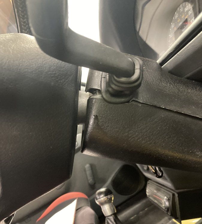
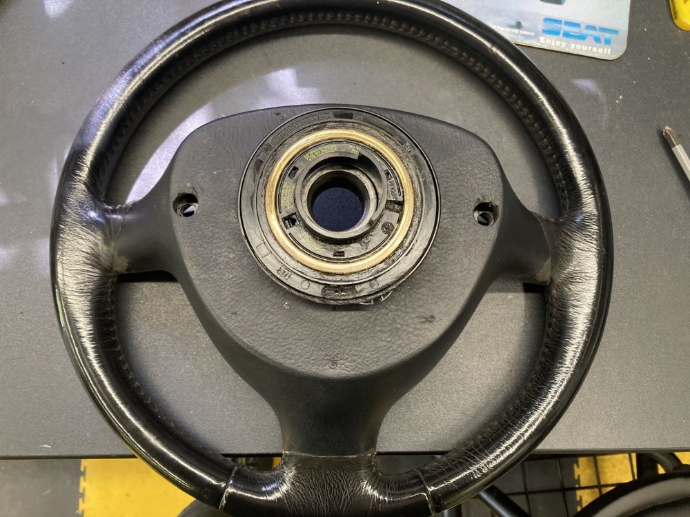
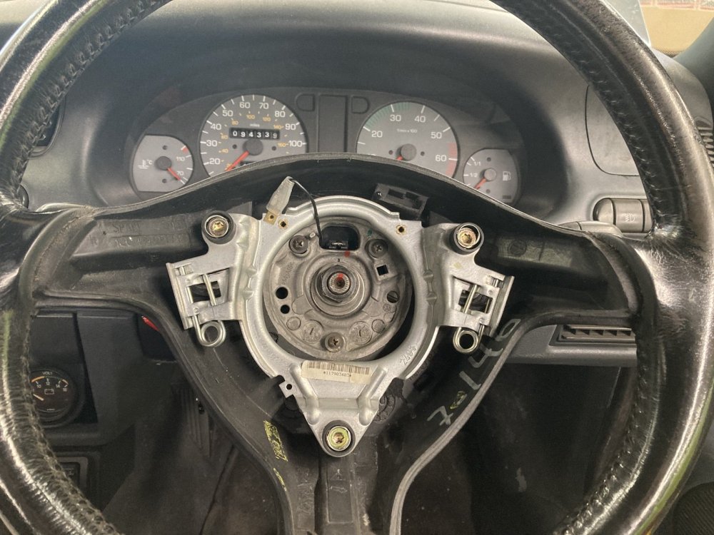
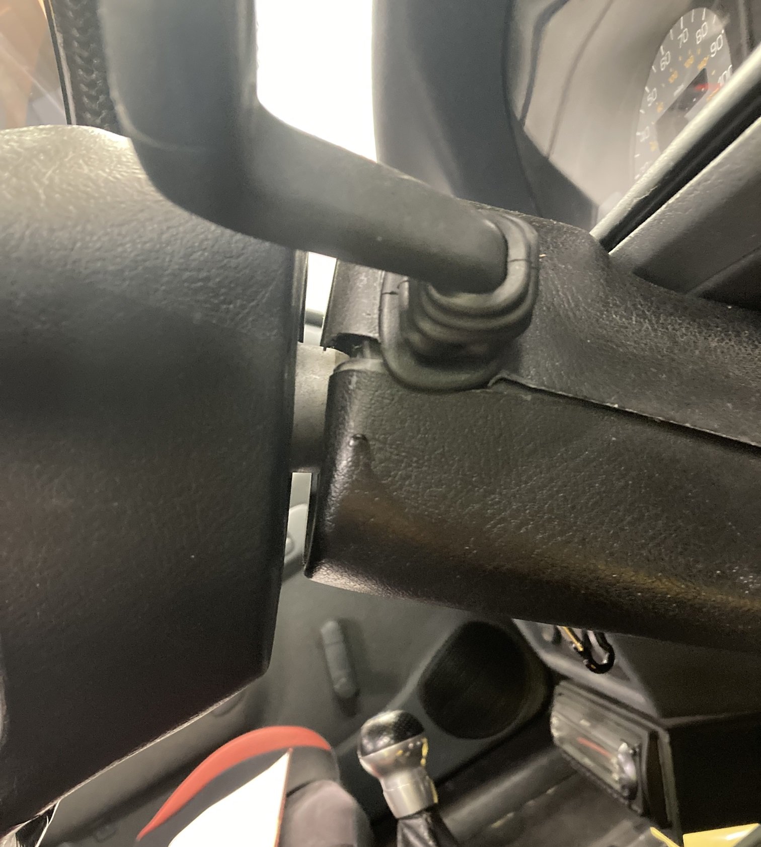
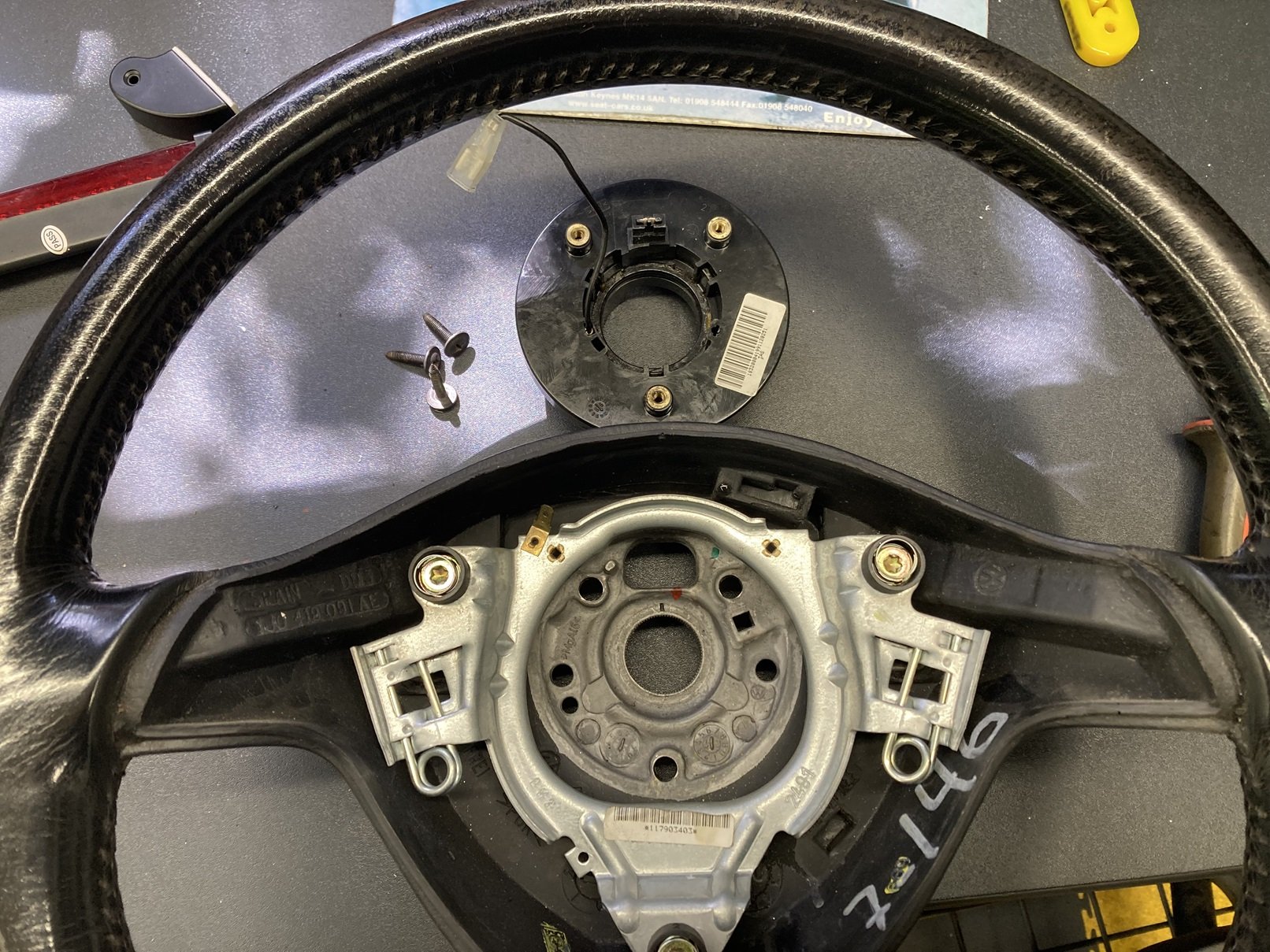
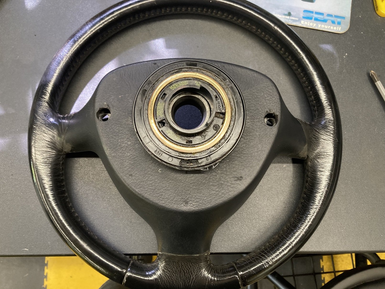
When I fitted the mk4 Golf steering wheel into the Caddy I did not seriously attempt getting the centre horn push to work. I had got used to using a horn button on the dashboard, and given the (mostly self-inflicted) difficulty I had getting the wheel fitted, I had no reason for expecting that the horn push would be straightforward. Then one day I was in the workshop doing something else when I noticed that the gap between the rear face of the Golf wheel and the sprung horn contact might just be conducive to a simple fix. I had a standard Felicia wheel in the garage, and it took only a couple of minutes to remove the horn contact ring from that, and barely longer to size it up against the gap it needed to fit into and confirm that it looked about right. Good enough to take the wheel off and have a closer look. Both the Golf wheel and the Felicia contact ring have three unevenly spaced mounting holes, which looked as if they were at approximately the same spacing, but the holes are not on the same PCD so I could not simply bolt them together. All I had to do to get round this was to open up the holes on the wheel a little with a drill, and then use flanged screws to attach them together. With that done, in classic Haynes manual style, reassembly was a reverse of the process involved to take it apart. I retained the dashboard mounted horn button as well, partly because it was there already and there was nothing to be gained from removing it, but mostly because my eldest grandson likes to go in the workshop and sound the Caddy’s horn, using that button, so I definitely do not want to spoil his fun.

-
Good on you for taking this on. Have you got some more general photos you can share on here? The mk1 Caddy has nothing in common with the mk2 Caddy / Felicia pick-up body-wise, so any similarity between the repair panels is going to be coincidental I suspect.
-
@Quadra840AV Thanks for letting me know me know you are enjoying my thread. I do not write it for the attention, but it is good to hear that my efforts are appreciated nonetheless. I have my own never-ending project in a mk2 SEAT Ibiza, so I understand the vagaries of motivation.
-
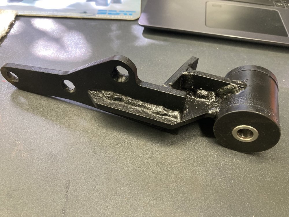
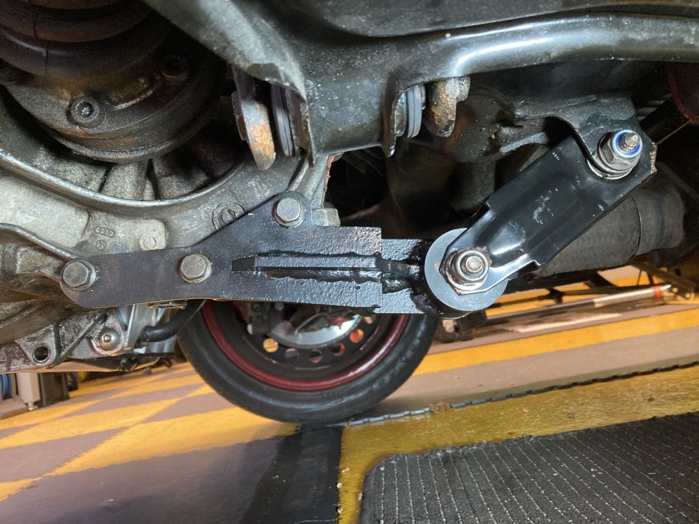
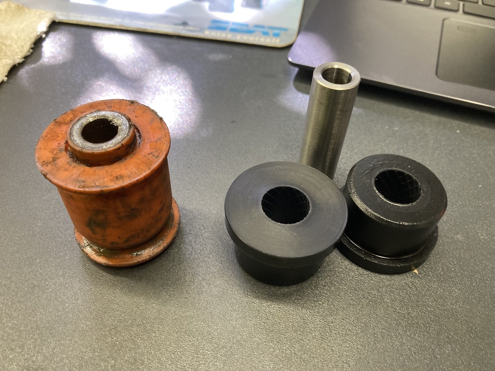
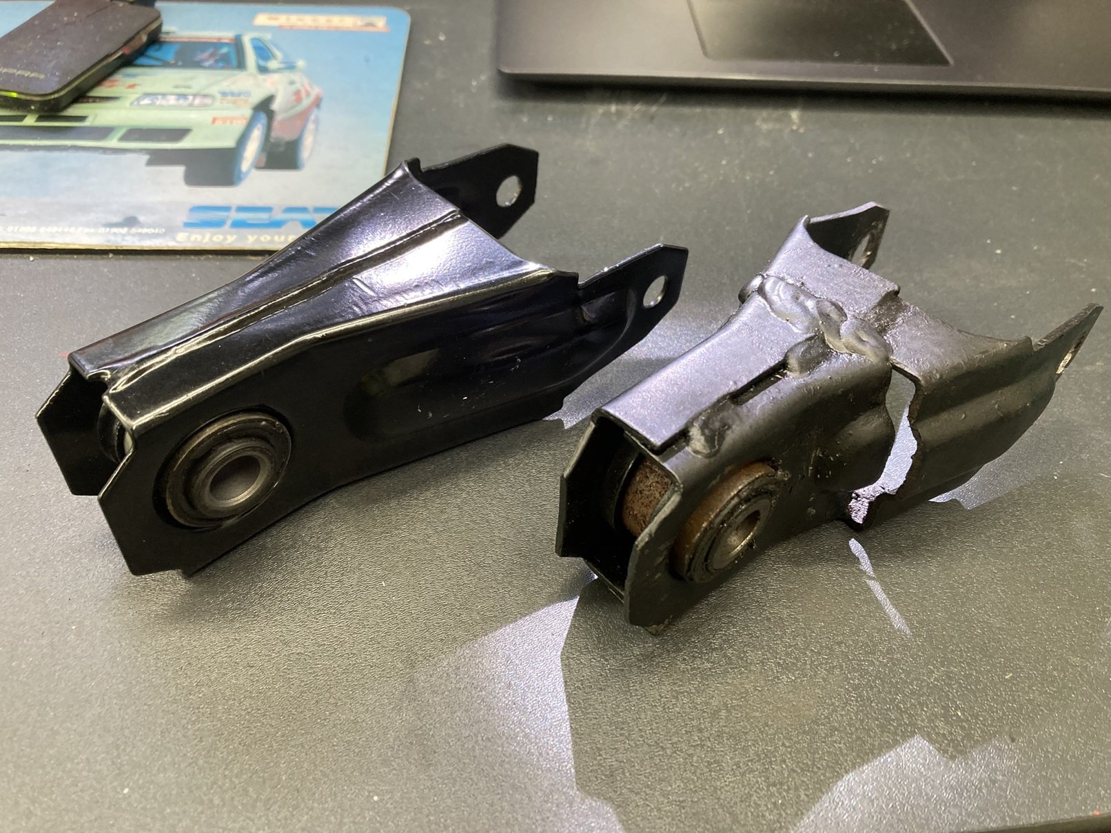
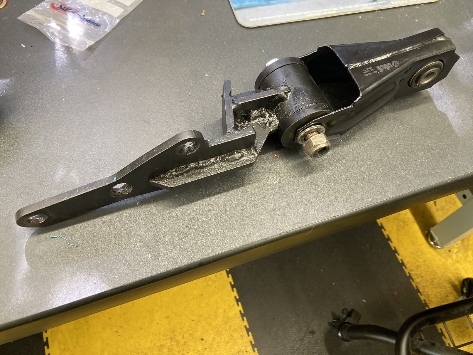
The engine mountings for the Caddy have never been brilliant. Either side it has Vibra-Technics mounts which I believe to be mk4 Golf parts, and they are fine, but the third mounting has always been a bit ineffective, and it had apparently been deteriorating. When the transplant was originally done, into the Felicia, a custom rear mounting was fabricated. This bolts onto the bottom edge of the bellhousing and to a modified Felicia subframe mounting through what was described as a Mazda MX-5 track control arm bush. This bush is the orange one in the picture, and was under suspicion as it was looking tired and there was a definite clunking noise from the rear of the engine under torque. I ordered a replacement Powerflex bush, but then when I had the mounting off the Caddy it was clear that the new bush was not the right part. Nonetheless I pressed the worn bush out of the mounting, and once I had cleaned it up I could see markings saying Polybush and 27C. This confirmed it as an MX-5 front lower wishbone rear bush, so the corresponding Powerflex replacement was ordered. After the bracket had been given a lick of paint and the new bush was pressed into place, the front half of the mounting was looking in much better shape. The rear half of the mounting was a modified Felicia part, which had been cut and re-welded to leave it shorter than standard. I assume this was done to make the two halves of the mounting line-up straighter when fitted. I tried and failed to source a replacement bush to fit the modified bracket, so instead I bought the whole thing. I reasoned that I would fit the standard length part to see how it looked, and I would shorten it only if I could see for myself that it needed doing. All assembled and ready to bolt into place. It was much easier to line-up all the bolts to fit the re-bushed mounting than it ever had been to do so for the shorter version, but whether that is a good thing I am not sure. One issue I spotted when I fitted it was that that rearmost bolt, through the mounting on the subframe, was not metric. This meant that it was not as snug a fit as it should be. I found a metric bolt to replace it and it felt much more solid than it had. The road test convinced me that the engine mounting is now in a much better state than it was before.


-
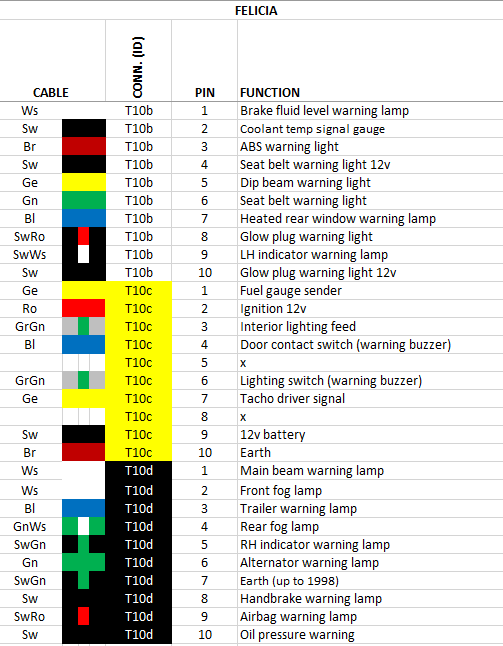
@vucko1011 No problem. I was looking for this info myself a while back and when I could only find an incomplete list I made a test rig so I could fill-in the gaps.
-
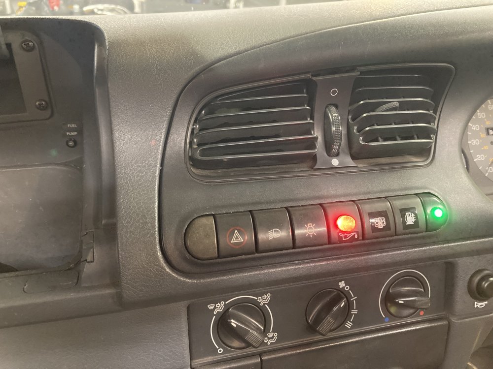
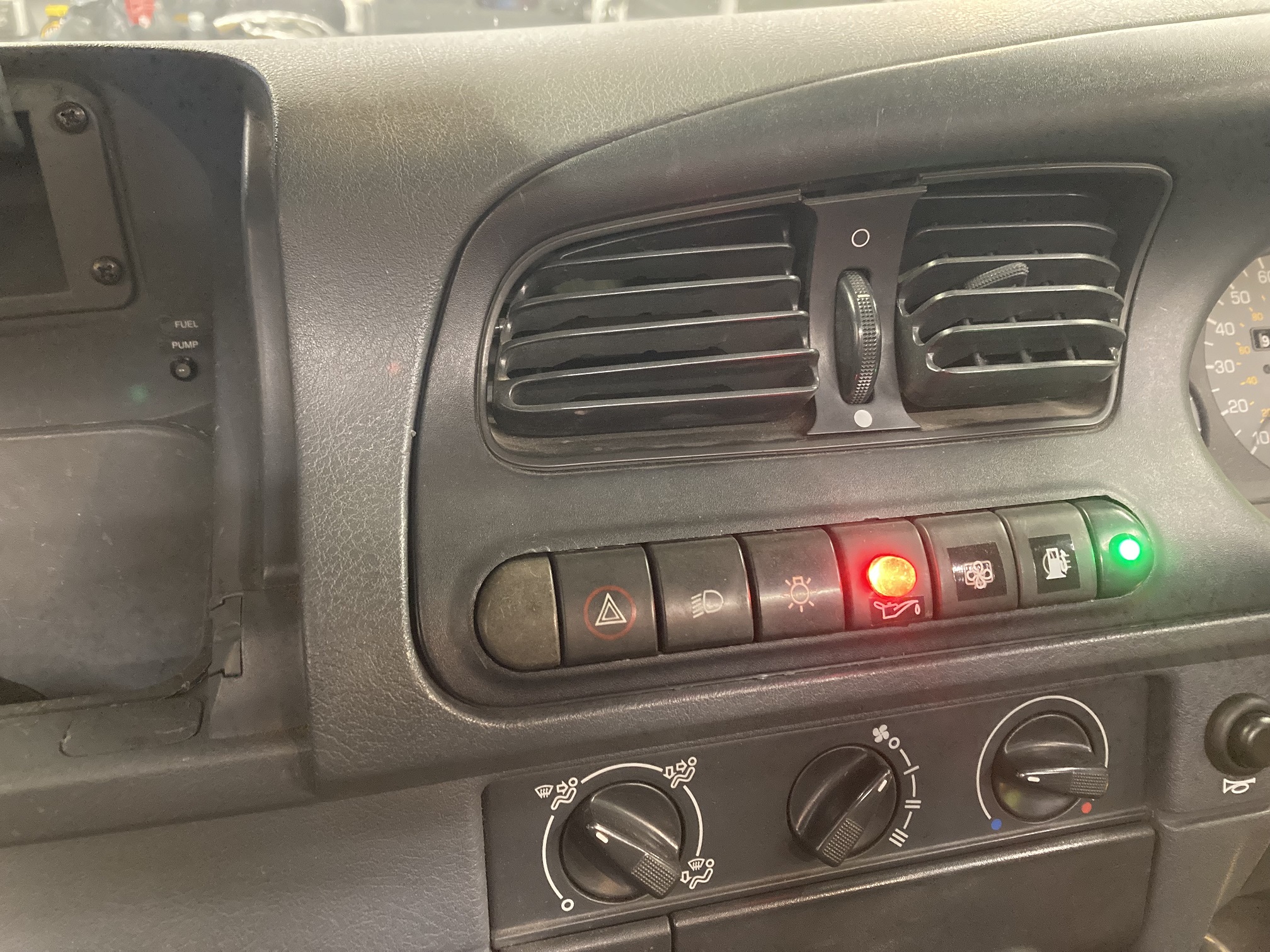
I had been chasing an intermittent fault on the Caddy for months. It would run perfectly, sometimes for ages, then it would lose power, often leading to the engine cutting-out altogether. Whether or not it would restart immediately was unpredictable too. My suspicion fell onto the fuel pump control circuit, and bypassing the fuel pump relay seemed to do the trick as a temporary fix for a while, but this also proved to be less than 100% effective. By this point I had decided there had to be two separate faults, unlikely though that seemed. I made-up a couple of test leads with LEDs so I could observe the function of the fuel pump relay control circuit from the driver’s seat, and this convinced me that the ECU control output was intermittent. The ECU now fitted to the Caddy is itself a replacement which I bought relatively cheaply off eBay a few years ago, so I thought I could easily get another. When I looked I found that the going rate has more than doubled since I bought the last one, and I was not keen to pay £300, so another solution was required. The ECU fuel pump control output is active for a short time when the ignition is switched on, then is deactivated until the ECU detects that the engine is running. Whilst the engine is running the fuel pump is energised constantly, then it is stopped once the engine stops, so that in the event of an accident which causes the engine to stop, the pump will not keep pumping petrol. This seems to me like a pretty desirable safety feature, so I wanted to retain this rather than simply install an override switch to keep the pump running whenever the ignition is on. The obvious solution (to me, at least) was to use an oil pressure switch output to provide the signal to indicate when the engine has stopped running, combined with a simple override to give the initial burst prior to starting. The Caddy has two oil pressure switches fitted, with the additional one feeding an LED located in the row of switches below the central heater vents, so it was straightforward to connect this additionally to a relay circuit to control the fuel pump. The photo shows the revised layout of switches in the dash centre, with the fuel pump override tell-tale LED (green) at the far right, next to the associated switch. The big red LED is from the extra oil pressure switch which I also use to feed the fuel pump control circuit. Inside the glovebox you can see another (green) LED which indicates when the fuel pump relay is energised. I had wired this when I was fault-finding the circuit, and I decided to keep it. It is not illuminated in this picture because I also have a security cut-out switch which was activated when the photo was taken. Having got a solution in place for the pump control circuit, attention now turned to the pump’s power supply. I identified a couple of connections I did not much like the look of, and rectified those, but still the problem persisted. Eventually I tested it with the fuel pump powered direct from the battery, but it still cut out. The pump itself looked like being the culprit, and as this was only a few months old it meant a trip to JKM who had supplied and fitted the Deatschwerks pump which had now failed. Apparently there have been a few recent instances of quality issues with these pumps, which is worrying as I have also installed one in my Ibiza. Jim swapped the failed pump for an APS unit, and after he had also found and repaired a dodgy connection it appears we have got this resolved. After I got the Caddy home I tried running it without my tertiary pump control circuit connected, and it duly misbehaved again, which confirmed that the issue had not just been the fuel pump itself, and the ECU output was (and is) also intermittent.
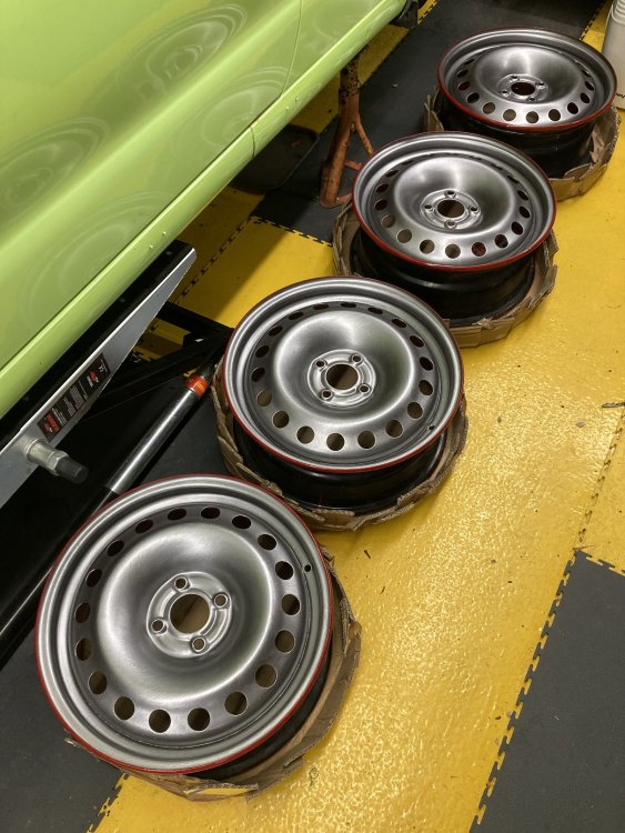
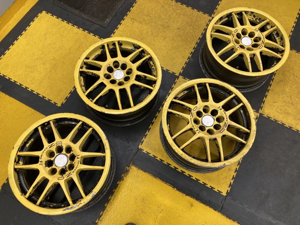
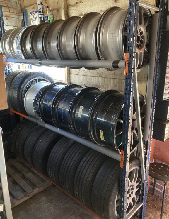
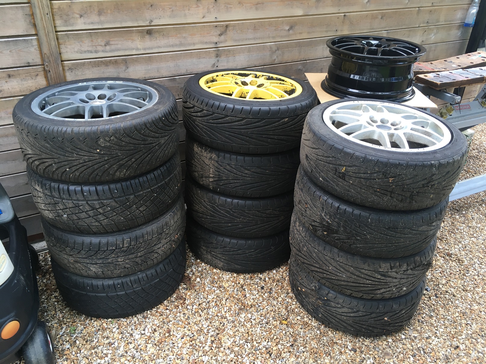
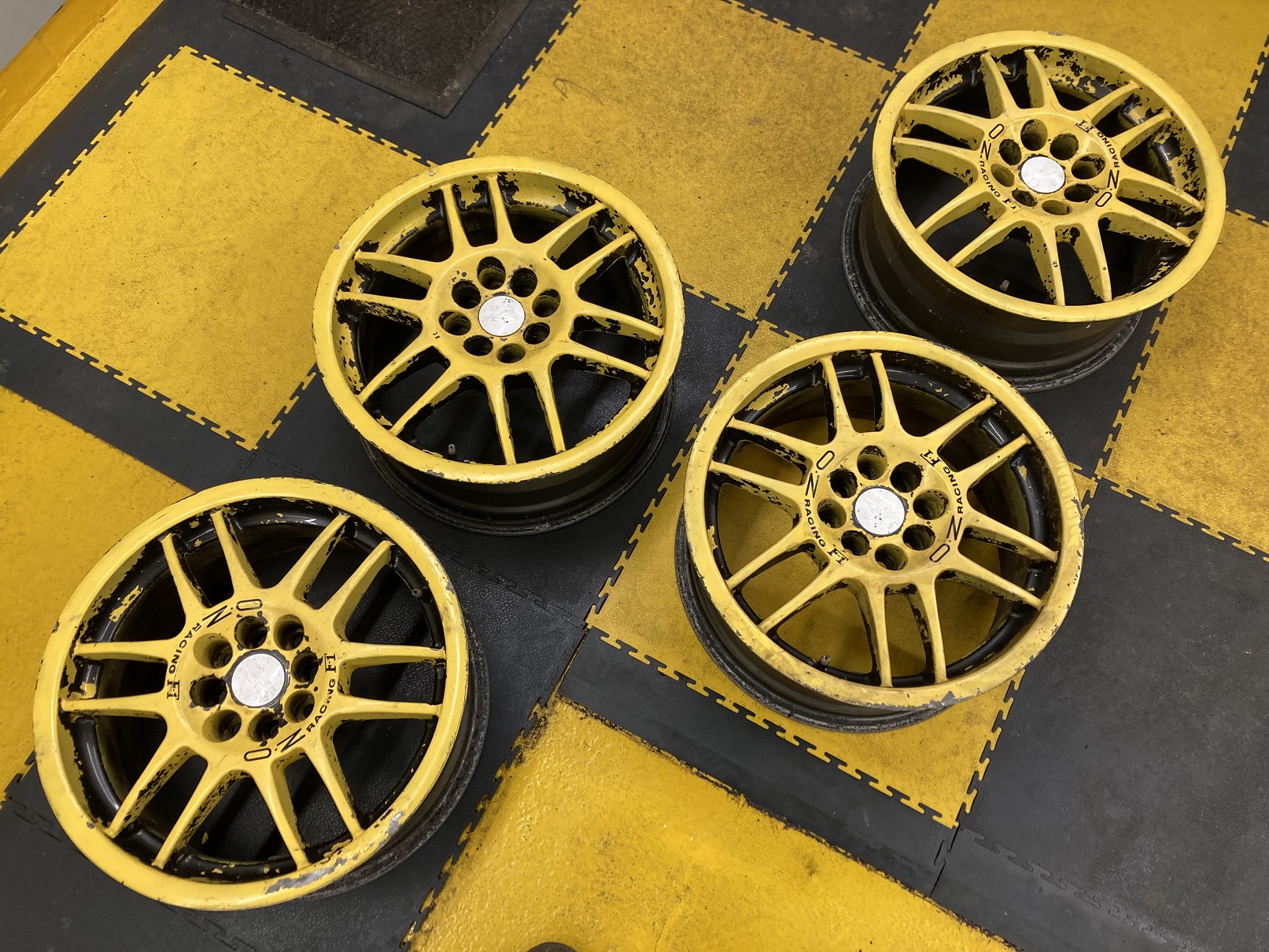
 On my Octavia there was an insulating 'bag' which fitted over the heater hoses and protected them from the heat from the turbo. It was a standard part, but I cannot find a part number or reference for it anywhere, can anyone help? I have a similar arrangement with the heater hoses in my Ibiza track project and I would like to source one of these insulating bags for it.Bete Noir replied to ChinaBoyZ31's topic in Skoda Favorit, Skoda Felicia, Skoda Fun and Skoda FormanI do not have experience air ride, but for coilovers mk1 Ford Focus parts are a better fit than mk4 Golf on the frontIt sounds like you might still have an earth issue. Have you done a continuity test between the earth pin at the light cluster connectors and the vehicle earth? I realise this question is too late to be helpful, but is there not an 8-way connector in the NSR car loom you can take all the towing connections from? On my pick-up there was one, and it meant I could simply make up a towing connector loom to go between the plug and socket of the original connector. My thread here has pictures.I own a lot of wheels. Even considering that I have three viable cars and the same number of projects, I have sufficient wheels that I have avoided keeping them all in the same place for fear that my partner might notice how many there are. Once I finally accepted I had thirteen Oz F-1s in 16” that I was unlikely ever to have a use for I reluctantly advertised them for sale. Two sets (the grey and the silver ones in the picture) had tyres which were worn or perished or both, and I sold those quickly and cheaply to people who needed a different size of tyres anyway. The yellow ones had a decent set of Toyo T1-Rs on them so I wanted to see a better price, which was not forthcoming at the time. My solution to this would not be the obvious one to most people, because my plan was to buy another set of wheels. I reasoned that if I found a set of 16” steel wheels for the Caddy, I could fit the Toyos to those, then sell the yellow Oz wheels without tyres, and also sell the black 15” steel wheels which are on the Caddy in earlier posts on this thread. It took a while, but eventually I found a set of Renault Megane Scenic 16” steel wheels which are 4x100 PCD to suit the Caddy. I had been debating whether to paint them in the same grey as the bodywork, but instead I decided on VW LA7Y which is my favoured gunmetal shade for alloy wheels. I wanted to put a red pinstripe on them but I could not work out how to do this neatly until I noticed the lip on the rim. The backs and lips were painted in the same Hammerite ruby red I used on the fronts of the other 15” wheels, and finally after three coats the coverage of the gunmetal looked passable too. Once the T1-Rs (in 205/45 R16) came off the Oz F-1s and onto these Renault wheels, the F-1s went back on eBay. Ironically, they sold for a price that I would happily have accepted for them previously complete with tyres. Happy days indeed. The Renault wheels sat in a stack in the corner of the workshop for a while, but eventually I got them onto the Caddy. They look a bit more ‘scene’ than I was hoping, but I am pretty pleased with them nonetheless. This does now mean I have more Winter-oriented tyres on my 16” wheels and more Summer rubber on the 15” wheels, which is probably the wrong way round, but as part of the object of the exercise was to find a use for the good Toyo tyres this was unavoidable. Meanwhile the black 15” steel wheels were also sold. Having rationalised my wheel collection by selling thirteen Oz F-1s and four steel wheels, I am still not exactly suffering from a wheel shortage!
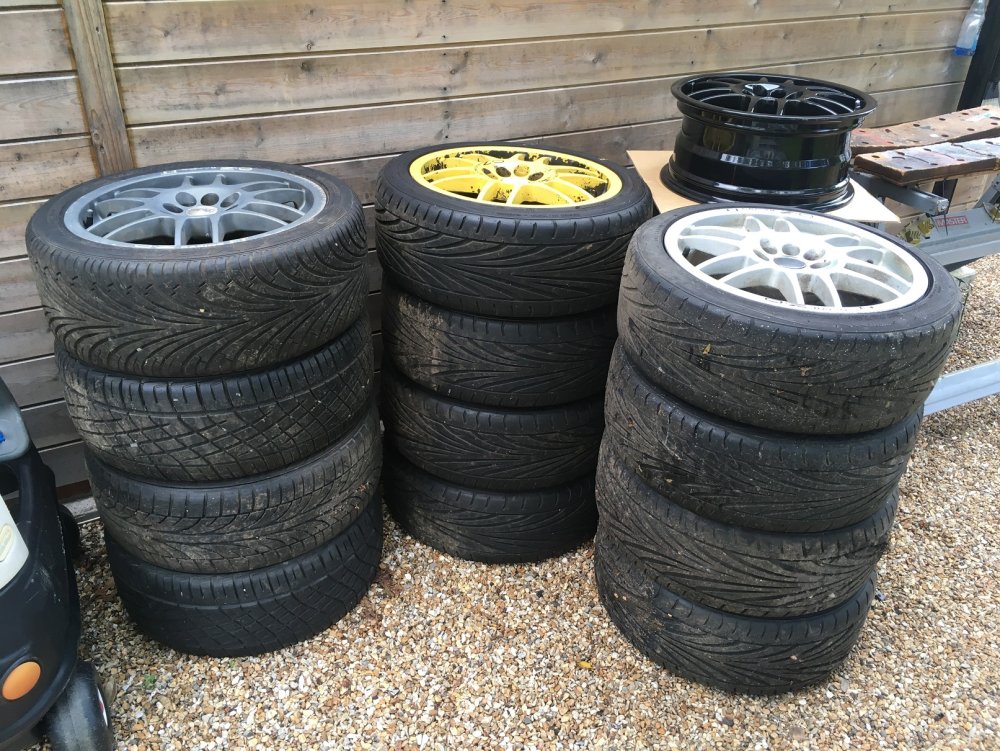

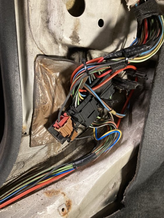
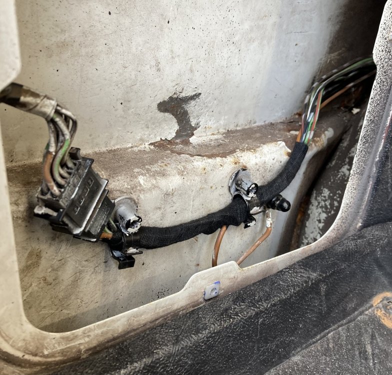
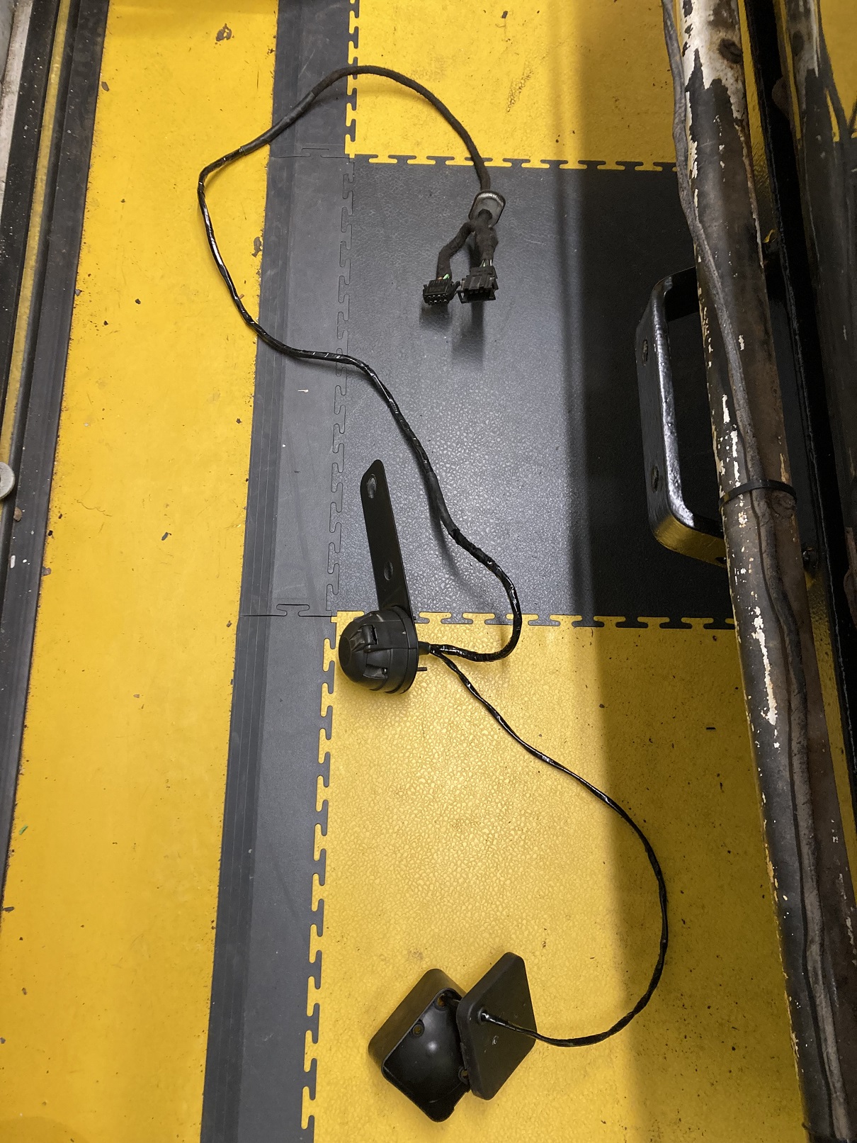
 There was a Caddy towbar in my lock-up for years. I cannot even remember where I got it from, but I guess I must have spotted it for sale locally and thought I might as well get it ‘just in case’. After I retrieved it from the lock-up it did sterling service as a doorstop for my workshop for another couple of years, before I figured I may as well fit it to my Caddy. When I removed the NSR access panel inside the load area, I found evidence that it had previously had a towbar fitted, but sadly that evidence was in the form of Scotchlok connectors still attached to the wiring harness. The previous owner had compounded the mess by attaching cables to feed his high level brake light (see post #1). This had to go. After I had prised the dreaded Scotchloks off the cables, I was able to remove the pins one at a time from the 8-way connector and slip some heatshrink over them to repair the damage to the cable insulation. With the pins then replaced I wrapped the loom in coroplast tape. I got quite a bit of the white overspray off the connectors whilst I was there. Now the standard wiring was looking more like it should, and it was ready to have the towing connector wiring added. The approach I decided to take was to make up a splitter loom to connect between this plug and socket, with another branch going to the towing connector. I suspect this may have been how it was done if the towbar was fitted as a factory option, judging by the blanking grommet I found adjacent to where the standard wiring goes through to the NSR light unit. It was only once I had made up this additional loom and connected it for testing that I realised the OSR light unit must have been from a LHD car, as it had a reversing light rather than foglight lens. This gave me the idea of wiring this as a reversing light, and adding a foglight below the bumper. The wiring for this was achieved by using the wire already in place across the rear for the OS reversing light, and running cables from the towing connector to the new foglight. Once I had confirmed that everything was working OK with the splitter loom connected, I removed it to wrap it. When it was then re-fitted, a problem revealed itself, with the offside tail light no longer working. Even with the original wiring configuration restored and the splitter loom out of circuit, the tail light stubbornly refused to illuminate. When I unplugged the relevant light unit, I could measure 12v at the plug, but this disappeared as soon as a load (bulb, even LED) was connected. All the signs said I had a high impedance connection somewhere. This was traced to between the fusebox and the 8-pin connector behind the NSR access panel. Immediately I decided this was most likely to be where the Scotchlok had previously been attached. Maybe the Scotchlok blade had cut through part of the cable core. I cut out the offending section of cable and checked the impedance from the cut end back to the fusebox, which was fine. I took that to mean that I had identified the cause I soldered in a new length of wire where the Scotchlok had been located, but it made no difference. This was a nasty surprise, but then it probably was not the smartest thinking anyway. To preserve the cable colour code at the 8-pin connector I had replaced the damaged section of cable but retained the original terminal pin. There was no visible sign of damage or corrosion to the connector, but now I did what I should have done in the first place, and replaced the whole section including the terminal. Finally it was solved and I was able to refit the rear light units and bumper.
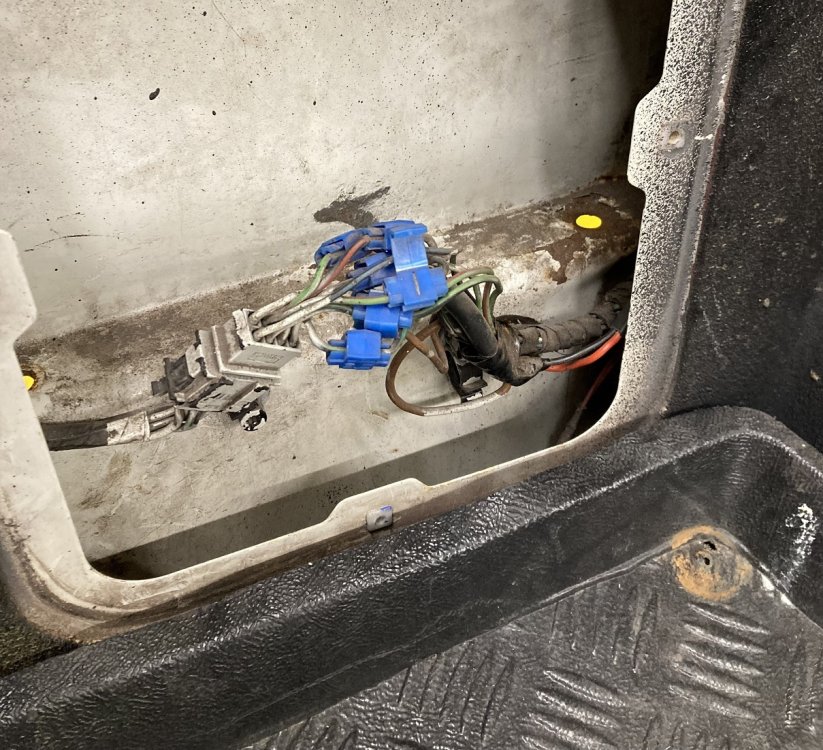


Important Information
Welcome to BRISKODA. Please note the following important links Terms of Use. We have a comprehensive Privacy Policy. We have placed cookies on your device to help make this website better. You can adjust your cookie settings, otherwise we'll assume you're okay to continue.