


Bete Noir
-
Posts
220 -
Joined
-
Last visited
-
Days Won
1
Content Type
Profiles
Forums
Gallery
Shop
Events
Downloads
Posts posted by Bete Noir
-
-
@vucko1011
No problem. I was looking for this info myself a while back and when I could only find an incomplete list I made a test rig so I could fill-in the gaps.-
 1
1
-
-
-
I had been chasing an intermittent fault on the Caddy for months. It would run perfectly, sometimes for ages, then it would lose power, often leading to the engine cutting-out altogether. Whether or not it would restart immediately was unpredictable too. My suspicion fell onto the fuel pump control circuit, and bypassing the fuel pump relay seemed to do the trick as a temporary fix for a while, but this also proved to be less than 100% effective. By this point I had decided there had to be two separate faults, unlikely though that seemed.
I made-up a couple of test leads with LEDs so I could observe the function of the fuel pump relay control circuit from the driver’s seat, and this convinced me that the ECU control output was intermittent. The ECU now fitted to the Caddy is itself a replacement which I bought relatively cheaply off eBay a few years ago, so I thought I could easily get another. When I looked I found that the going rate has more than doubled since I bought the last one, and I was not keen to pay £300, so another solution was required.
The ECU fuel pump control output is active for a short time when the ignition is switched on, then is deactivated until the ECU detects that the engine is running. Whilst the engine is running the fuel pump is energised constantly, then it is stopped once the engine stops, so that in the event of an accident which causes the engine to stop, the pump will not keep pumping petrol. This seems to me like a pretty desirable safety feature, so I wanted to retain this rather than simply install an override switch to keep the pump running whenever the ignition is on.
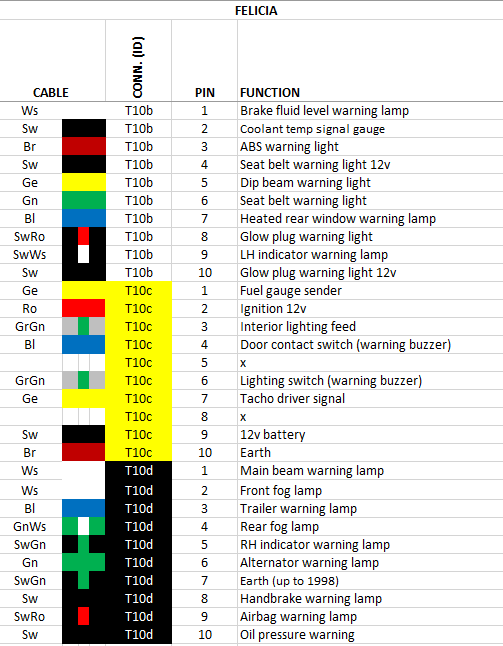
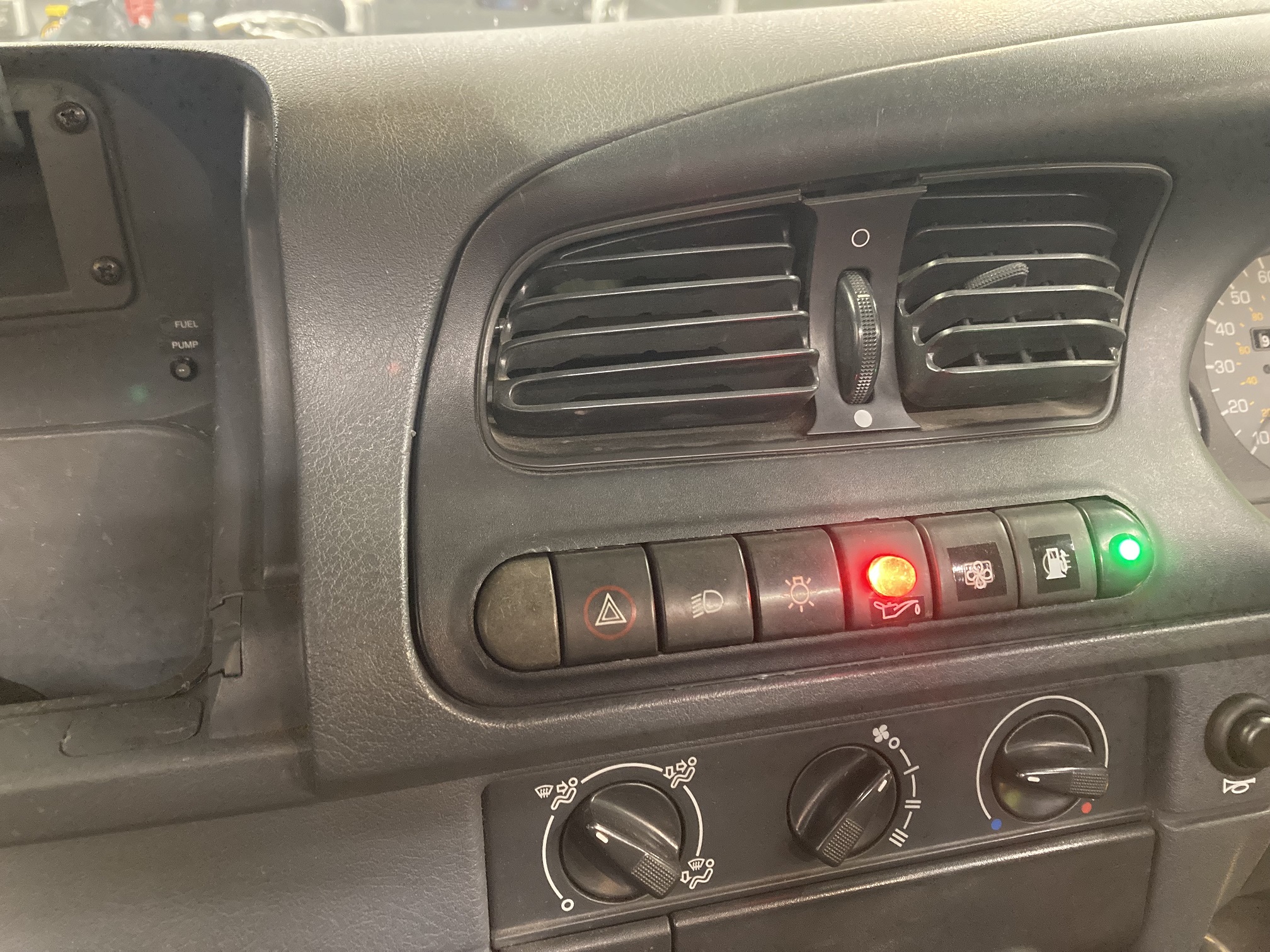
The obvious solution (to me, at least) was to use an oil pressure switch output to provide the signal to indicate when the engine has stopped running, combined with a simple override to give the initial burst prior to starting. The Caddy has two oil pressure switches fitted, with the additional one feeding an LED located in the row of switches below the central heater vents, so it was straightforward to connect this additionally to a relay circuit to control the fuel pump. The photo shows the revised layout of switches in the dash centre, with the fuel pump override tell-tale LED (green) at the far right, next to the associated switch. The big red LED is from the extra oil pressure switch which I also use to feed the fuel pump control circuit. Inside the glovebox you can see another (green) LED which indicates when the fuel pump relay is energised. I had wired this when I was fault-finding the circuit, and I decided to keep it. It is not illuminated in this picture because I also have a security cut-out switch which was activated when the photo was taken.

Having got a solution in place for the pump control circuit, attention now turned to the pump’s power supply. I identified a couple of connections I did not much like the look of, and rectified those, but still the problem persisted. Eventually I tested it with the fuel pump powered direct from the battery, but it still cut out. The pump itself looked like being the culprit, and as this was only a few months old it meant a trip to JKM who had supplied and fitted the Deatschwerks pump which had now failed. Apparently there have been a few recent instances of quality issues with these pumps, which is worrying as I have also installed one in my Ibiza. Jim swapped the failed pump for an APS unit, and after he had also found and repaired a dodgy connection it appears we have got this resolved.
After I got the Caddy home I tried running it without my tertiary pump control circuit connected, and it duly misbehaved again, which confirmed that the issue had not just been the fuel pump itself, and the ECU output was (and is) also intermittent.
-
2
-
-
On my Octavia there was an insulating 'bag' which fitted over the heater hoses and protected them from the heat from the turbo. It was a standard part, but I cannot find a part number or reference for it anywhere, can anyone help? I have a similar arrangement with the heater hoses in my Ibiza track project and I would like to source one of these insulating bags for it.
-
I do not have experience air ride, but for coilovers mk1 Ford Focus parts are a better fit than mk4 Golf on the front
-
On 07/09/2022 at 23:20, R_U_AFA said:
Worked it out now, I had no continuity on the earth between the tow bar bracket electric socket and the rear light cluster
Everything works fine now, although the trailer tail or brake lights do dim a little when operated in unison with the indicators
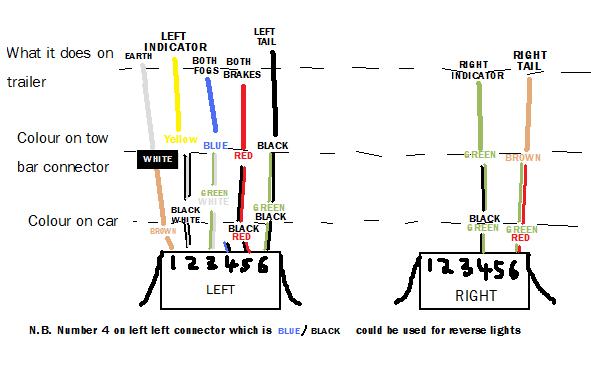
If I get time I'll post some wiring diagrams to help anyone in future
It sounds like you might still have an earth issue. Have you done a continuity test between the earth pin at the light cluster connectors and the vehicle earth?
On 15/06/2023 at 20:32, R_U_AFA said:This is the way I have wired in the tow bar electrics (7-pin) like I say it's straight into the rear loom no extra relays. Although the fog light wiring goes nowhere on the trailer as seen as it has no corresponding light.
Those are the connector blocks for the rear light units on the car (post facelift) but I think it's the same on early models. There also is a handy rubber body plug that goes into the boot under the light cluster which saves drilling through the steel boot floor, to feed the wire through.
I realise this question is too late to be helpful, but is there not an 8-way connector in the NSR car loom you can take all the towing connections from? On my pick-up there was one, and it meant I could simply make up a towing connector loom to go between the plug and socket of the original connector. My thread here has pictures.
-
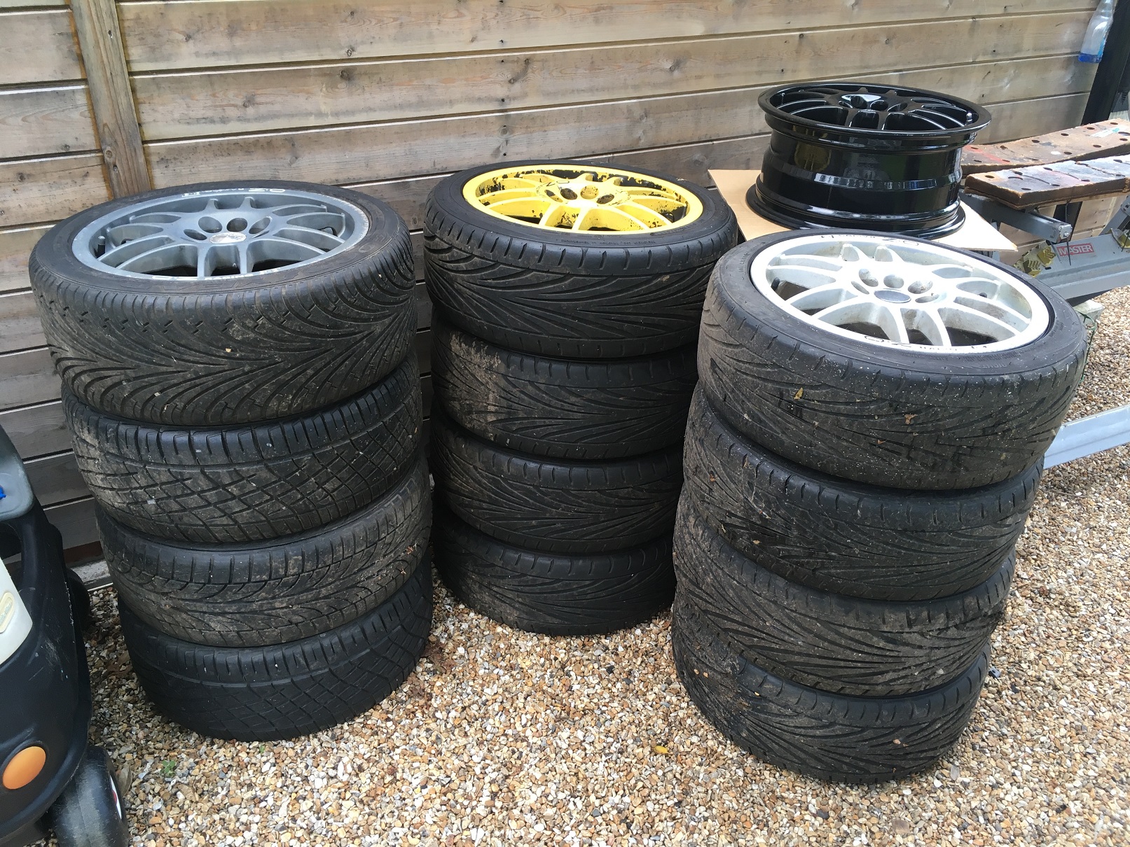
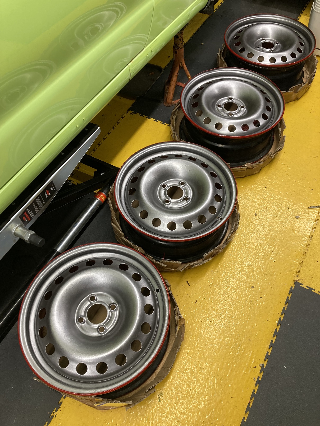
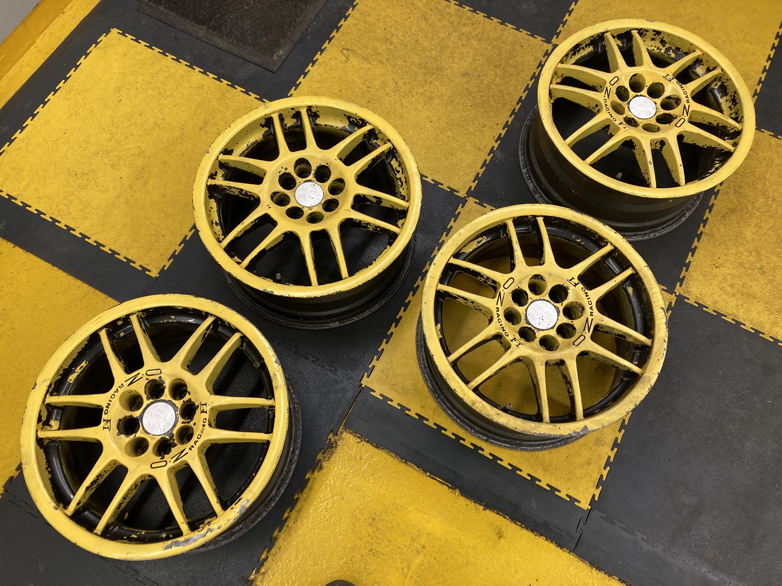
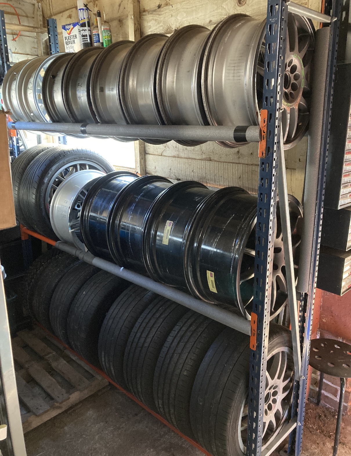
I own a lot of wheels. Even considering that I have three viable cars and the same number of projects, I have sufficient wheels that I have avoided keeping them all in the same place for fear that my partner might notice how many there are. Once I finally accepted I had thirteen Oz F-1s in 16” that I was unlikely ever to have a use for I reluctantly advertised them for sale.
Two sets (the grey and the silver ones in the picture) had tyres which were worn or perished or both, and I sold those quickly and cheaply to people who needed a different size of tyres anyway. The yellow ones had a decent set of Toyo T1-Rs on them so I wanted to see a better price, which was not forthcoming at the time. My solution to this would not be the obvious one to most people, because my plan was to buy another set of wheels.
I reasoned that if I found a set of 16” steel wheels for the Caddy, I could fit the Toyos to those, then sell the yellow Oz wheels without tyres, and also sell the black 15” steel wheels which are on the Caddy in earlier posts on this thread.
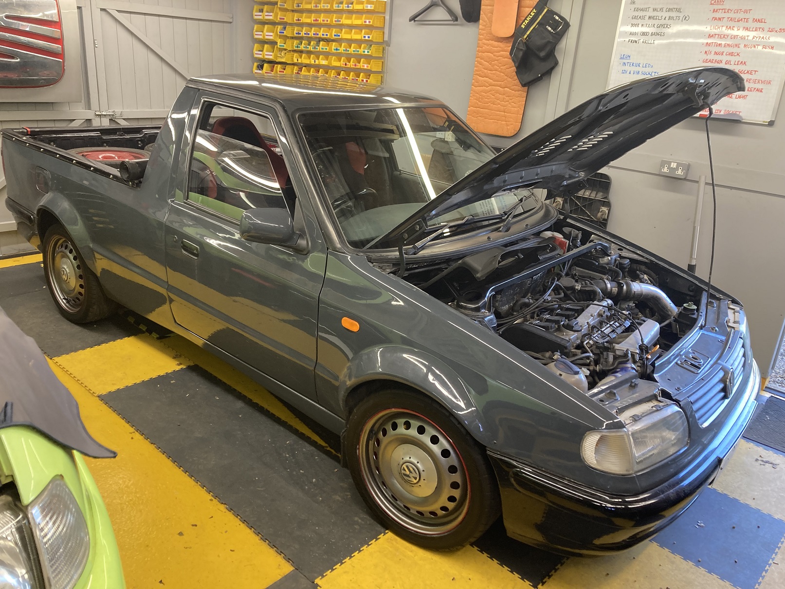
It took a while, but eventually I found a set of Renault Megane Scenic 16” steel wheels which are 4x100 PCD to suit the Caddy. I had been debating whether to paint them in the same grey as the bodywork, but instead I decided on VW LA7Y which is my favoured gunmetal shade for alloy wheels. I wanted to put a red pinstripe on them but I could not work out how to do this neatly until I noticed the lip on the rim. The backs and lips were painted in the same Hammerite ruby red I used on the fronts of the other 15” wheels, and finally after three coats the coverage of the gunmetal looked passable too.
Once the T1-Rs (in 205/45 R16) came off the Oz F-1s and onto these Renault wheels, the F-1s went back on eBay. Ironically, they sold for a price that I would happily have accepted for them previously complete with tyres. Happy days indeed.
The Renault wheels sat in a stack in the corner of the workshop for a while, but eventually I got them onto the Caddy. They look a bit more ‘scene’ than I was hoping, but I am pretty pleased with them nonetheless. This does now mean I have more Winter-oriented tyres on my 16” wheels and more Summer rubber on the 15” wheels, which is probably the wrong way round, but as part of the object of the exercise was to find a use for the good Toyo tyres this was unavoidable.
Meanwhile the black 15” steel wheels were also sold. Having rationalised my wheel collection by selling thirteen Oz F-1s and four steel wheels, I am still not exactly suffering from a wheel shortage!
-
1
-
 2
2
-
 1
1
-
-
There was a Caddy towbar in my lock-up for years. I cannot even remember where I got it from, but I guess I must have spotted it for sale locally and thought I might as well get it ‘just in case’. After I retrieved it from the lock-up it did sterling service as a doorstop for my workshop for another couple of years, before I figured I may as well fit it to my Caddy.
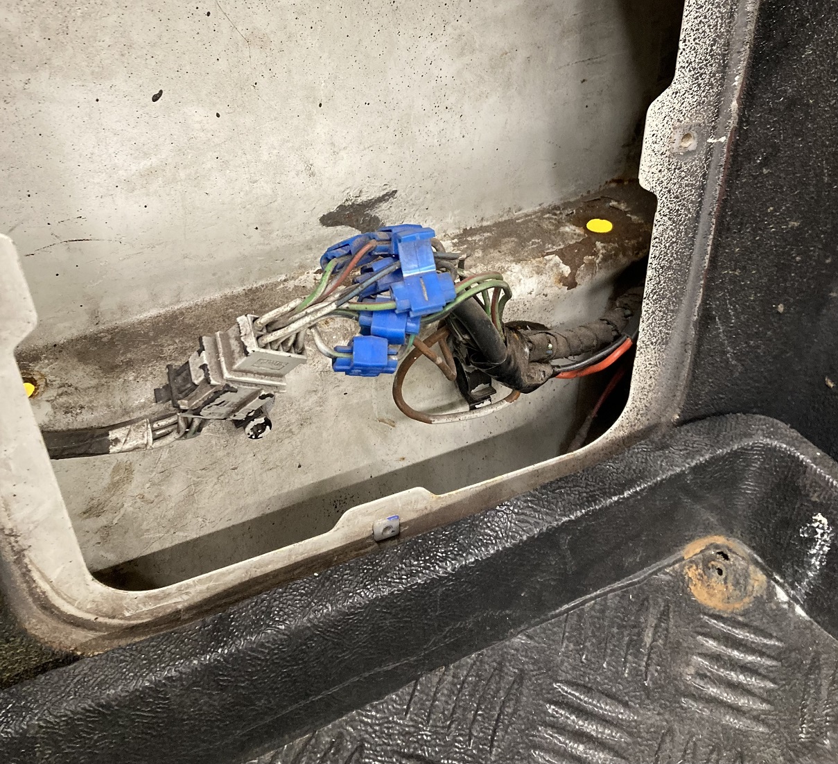
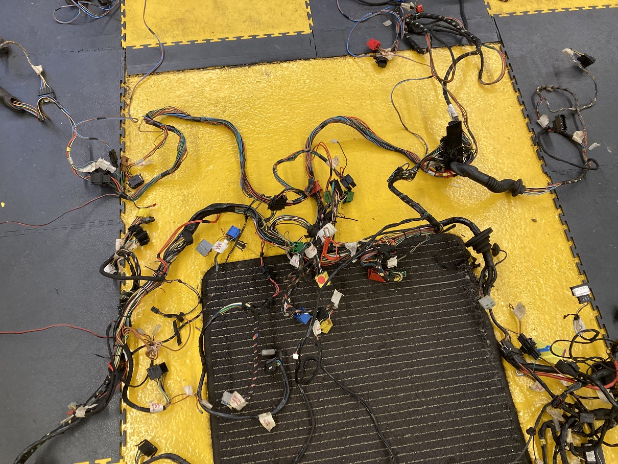
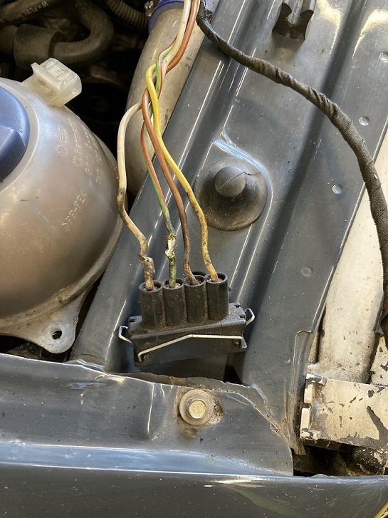
When I removed the NSR access panel inside the load area, I found evidence that it had previously had a towbar fitted, but sadly that evidence was in the form of Scotchlok connectors still attached to the wiring harness.
The previous owner had compounded the mess by attaching cables to feed his high level brake light (see post #1). This had to go.
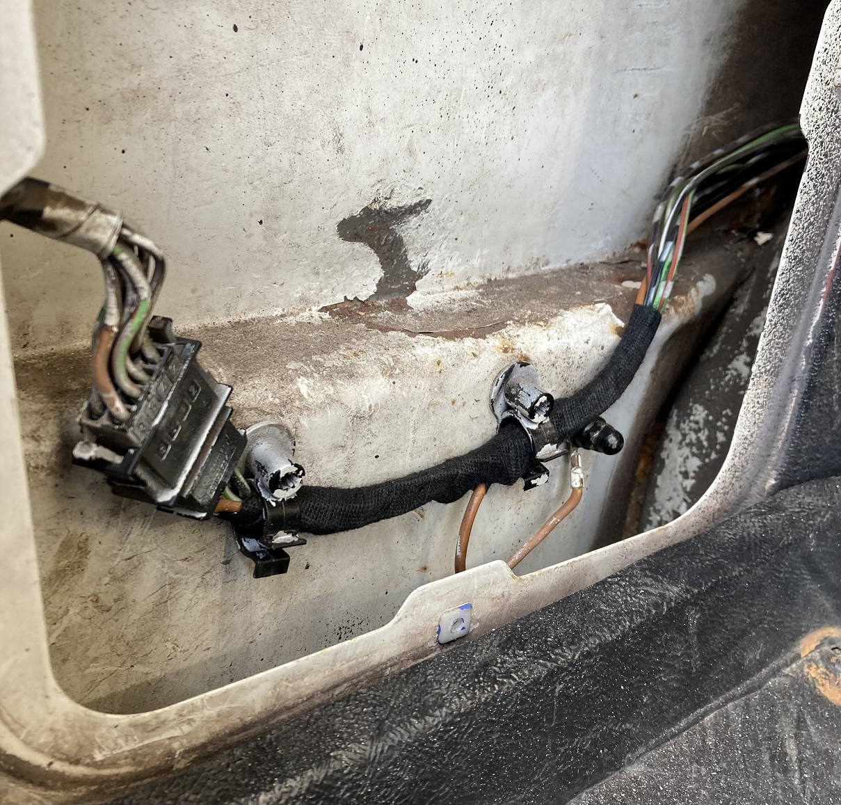
After I had prised the dreaded Scotchloks off the cables, I was able to remove the pins one at a time from the 8-way connector and slip some heatshrink over them to repair the damage to the cable insulation. With the pins then replaced I wrapped the loom in coroplast tape. I got quite a bit of the white overspray off the connectors whilst I was there. Now the standard wiring was looking more like it should, and it was ready to have the towing connector wiring added.
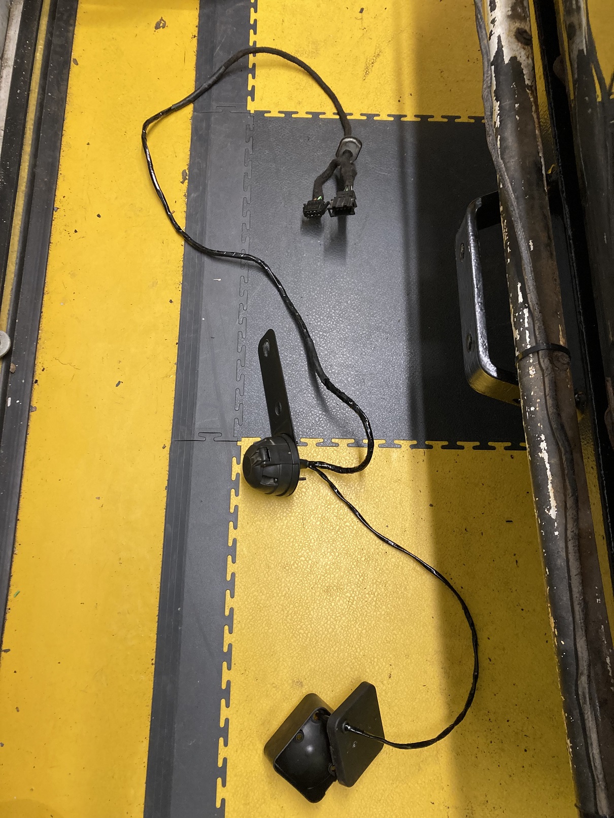
The approach I decided to take was to make up a splitter loom to connect between this plug and socket, with another branch going to the towing connector. I suspect this may have been how it was done if the towbar was fitted as a factory option, judging by the blanking grommet I found adjacent to where the standard wiring goes through to the NSR light unit.
It was only once I had made up this additional loom and connected it for testing that I realised the OSR light unit must have been from a LHD car, as it had a reversing light rather than foglight lens. This gave me the idea of wiring this as a reversing light, and adding a foglight below the bumper. The wiring for this was achieved by using the wire already in place across the rear for the OS reversing light, and running cables from the towing connector to the new foglight.
Once I had confirmed that everything was working OK with the splitter loom connected, I removed it to wrap it.
When it was then re-fitted, a problem revealed itself, with the offside tail light no longer working. Even with the original wiring configuration restored and the splitter loom out of circuit, the tail light stubbornly refused to illuminate. When I unplugged the relevant light unit, I could measure 12v at the plug, but this disappeared as soon as a load (bulb, even LED) was connected. All the signs said I had a high impedance connection somewhere. This was traced to between the fusebox and the 8-pin connector behind the NSR access panel. Immediately I decided this was most likely to be where the Scotchlok had previously been attached. Maybe the Scotchlok blade had cut through part of the cable core. I cut out the offending section of cable and checked the impedance from the cut end back to the fusebox, which was fine. I took that to mean that I had identified the cause I soldered in a new length of wire where the Scotchlok had been located, but it made no difference. This was a nasty surprise, but then it probably was not the smartest thinking anyway. To preserve the cable colour code at the 8-pin connector I had replaced the damaged section of cable but retained the original terminal pin. There was no visible sign of damage or corrosion to the connector, but now I did what I should have done in the first place, and replaced the whole section including the terminal. Finally it was solved and I was able to refit the rear light units and bumper.
-
4
-
-
Are you using Golf coilovers on the front? I considered them but was concerned about the amount of metal that needs to be removed from the hub carrier for them to fit. I went with mk1 Ford Focus front coilovers in the end because they are smaller diameter towards the bottom so they fit into the hub carrier much more readily.
-
Notwithstanding the fact that different markets have different prices, that does look like good value.
Fun prices appear to have been going up for a while in the UK, and in the last few months I have noticed that Felicia and mk2 Caddy pick-up prices are also on the rise, probably due to the very high prices for mk1 Caddys. Not that my Caddy will ever be worth what I have spent on it!
-
- Popular Post
- Popular Post
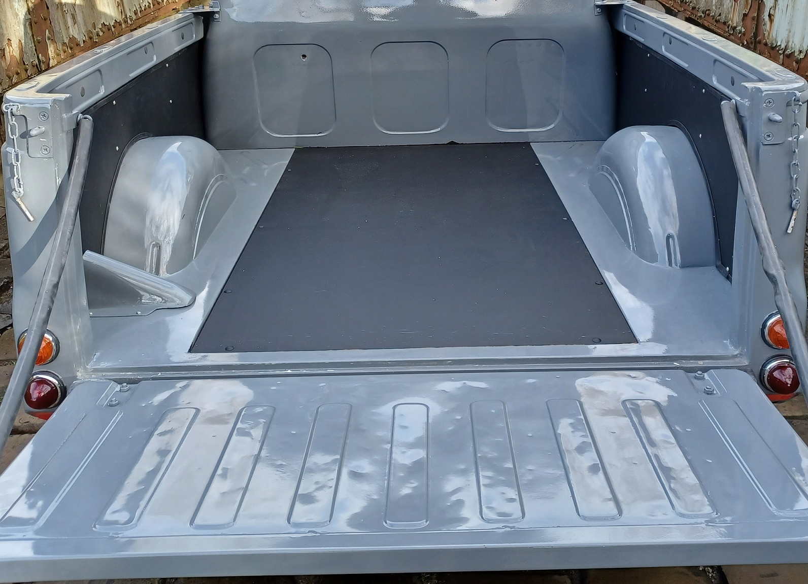
Real progress
Once back together, it was treated to a liberal coating of stonechip
-
5
-
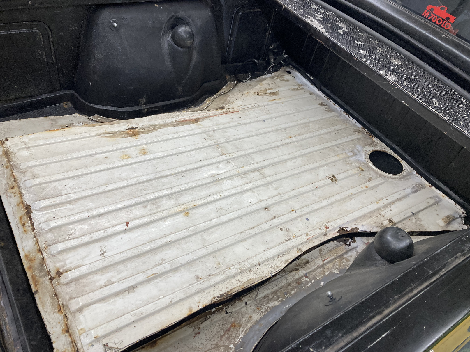
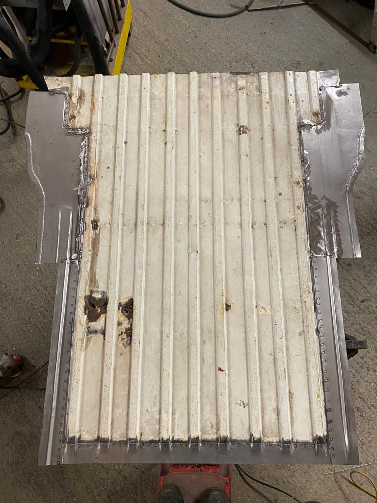
Any thoughts of a wooden floor ended abruptly when I spotted this on eBay.
I made the seller an offer, which was accepted sufficiently quickly to indicate it was too generous, and drove the Caddy up to Cambridge to collect it the following weekend. The seller had acquired this for his own Caddy project, but had decided he was unlikely ever to get around to it.
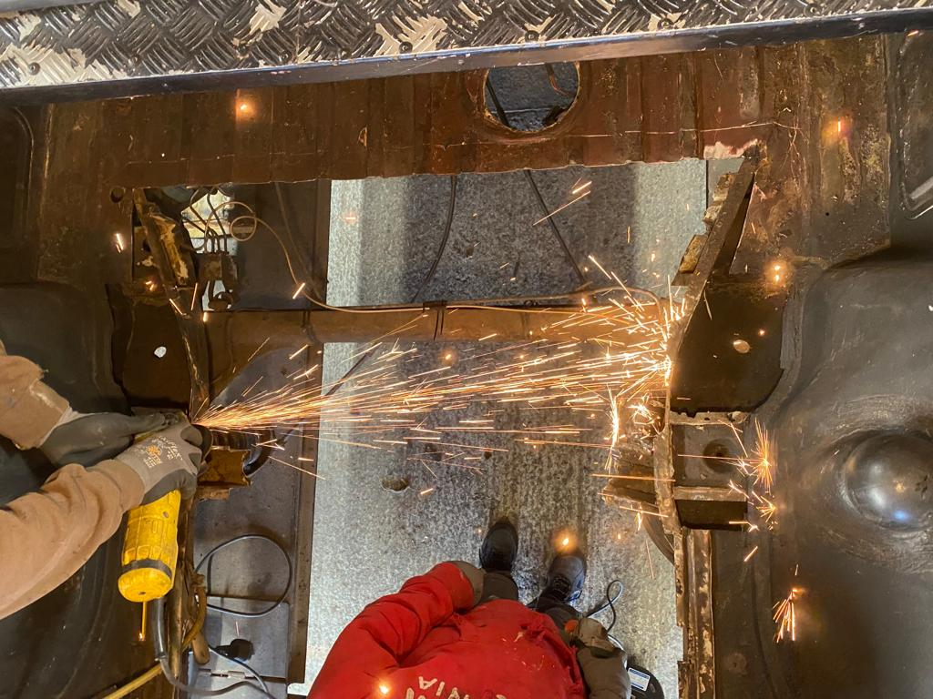
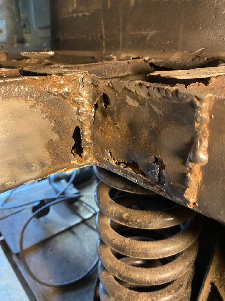
The fuel tank came out, and the serious surgery got underway.
Unsurprisingly, cutting away the previous dodgy repairs revealed some nasties which warranted remedial action.
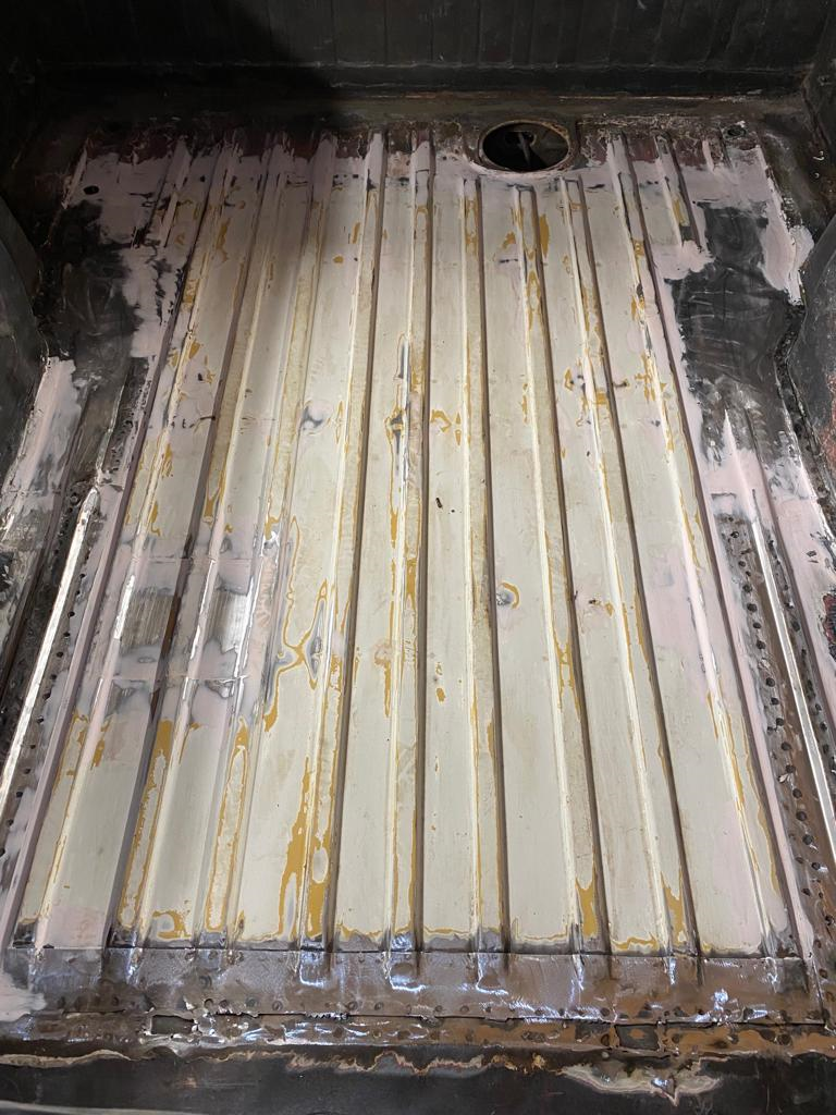
The replacement bed floor itself needed plenty of work before it was ready to be welded into place.
-
1
-
-
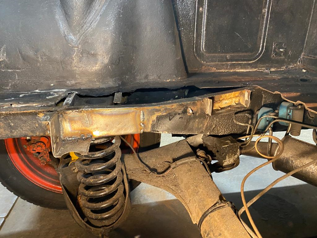
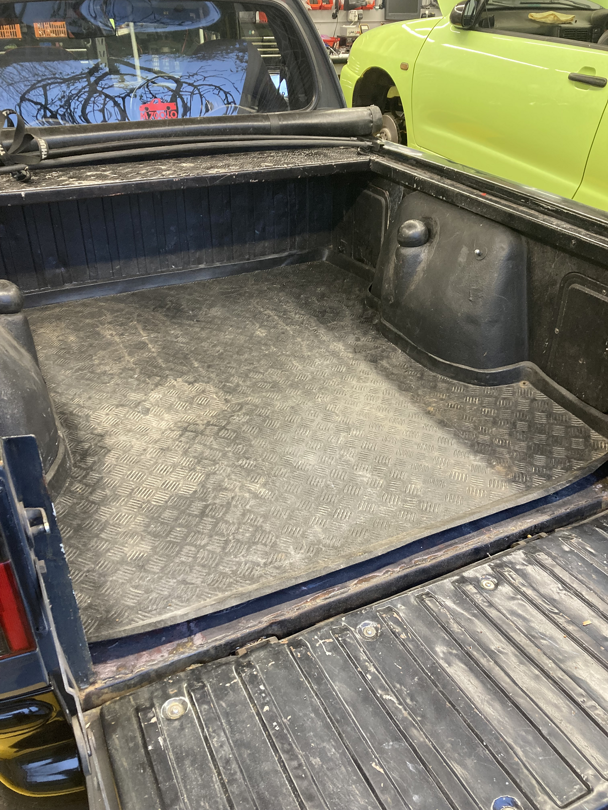
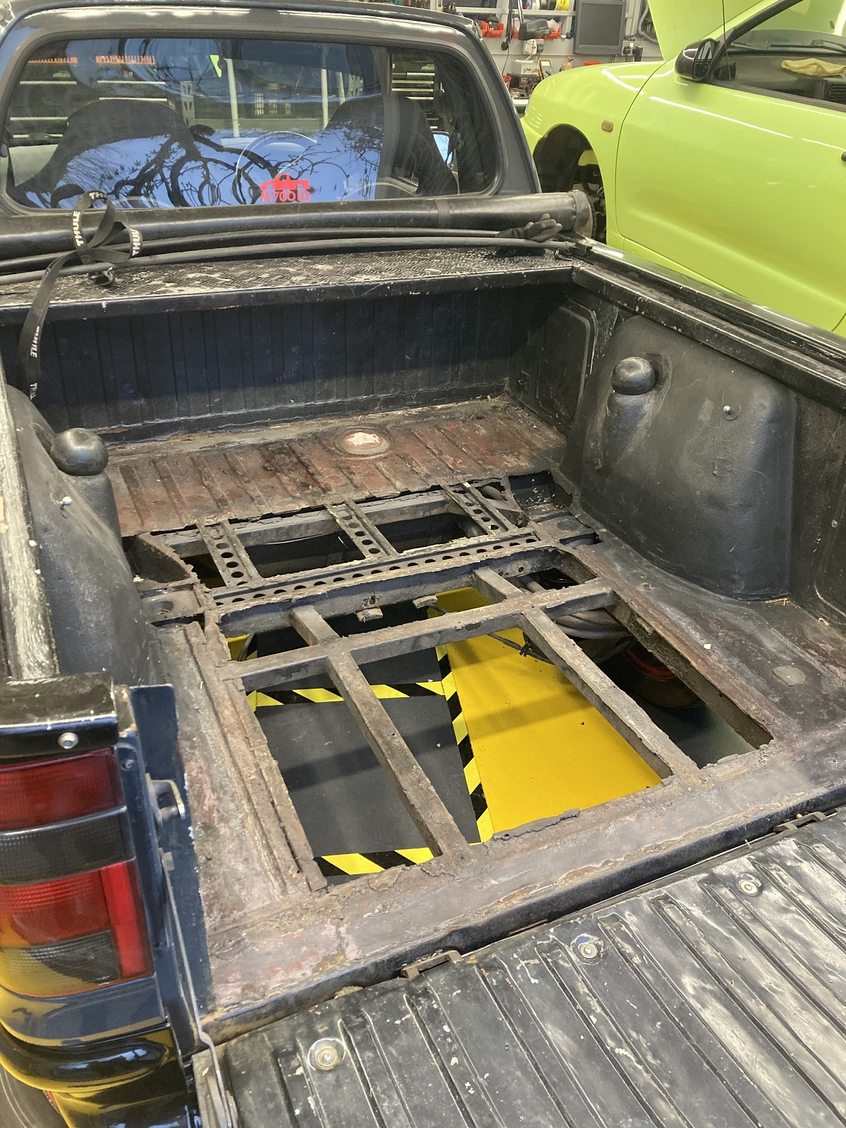
The rear bed of my Caddy must have rusted-out at some point, and in the absence of a proper replacement a previous owner had cut out the centre section, welded some additional bracing underneath, then riveted a sheet of steel over the top. It was pretty gash, but it served its purpose. The steel sheet covered the whole of the load area, which became problematic when I had to get access to the fuel pump. When I took the steel sheet out, I made a point of folding it up and putting it in the scrap, to remove any temptation to refit it.
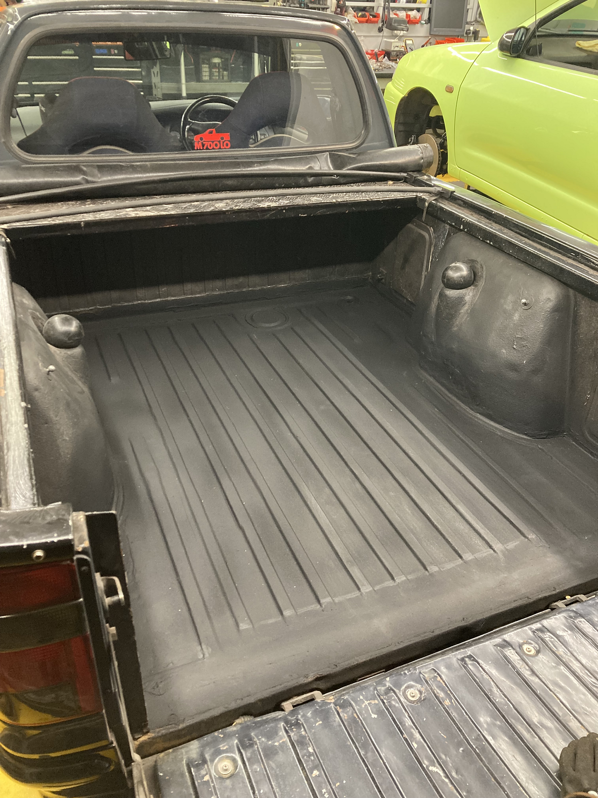
With the load bed liner in place, it did not look too bad.
Underneath it was ugly.
The bracing under the rear, in addition to its aesthetic failings, prevented the underfloor holder for the spare wheel from being used. All things considered, it had to go. I had been talking with Nick at S&P Autos about what form the repair should take, assuming that a return to standard was unlikely to be practicable, I had begun to think that a wooden floor section similar to the load bed in Morris Minor vans and pick-ups might be the way to go.
-
It is only fair to give the OP first refusal 🙂
-
Is this what you are after? It still has the door looms connected, but obviously I can unplug those. As far as I can see the only bit of the loom which has been messed-about with is that one of the side indicator repeaters has a superseal connector instead of the OEM one. I have more (and bigger) photos I can send you for you to scrutinise in detail.
I have no idea where you are located, so even if it is the correct part then it may be academic if transport is prohibitive.

-
1
-
-
It will be nice to see another 1.8T Felicia project. There are a few old threads on here with loads of useful info for the transplant.
-
I tried a pair of those LO springs on the back of my Caddy. They came off again almost straight away because they were too soft. If you ever carry anything in the back, I would avoid these springs if I were you.
-
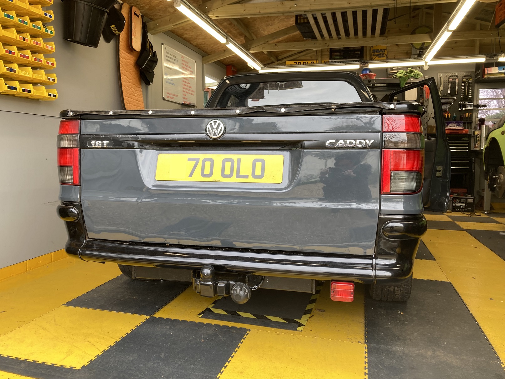
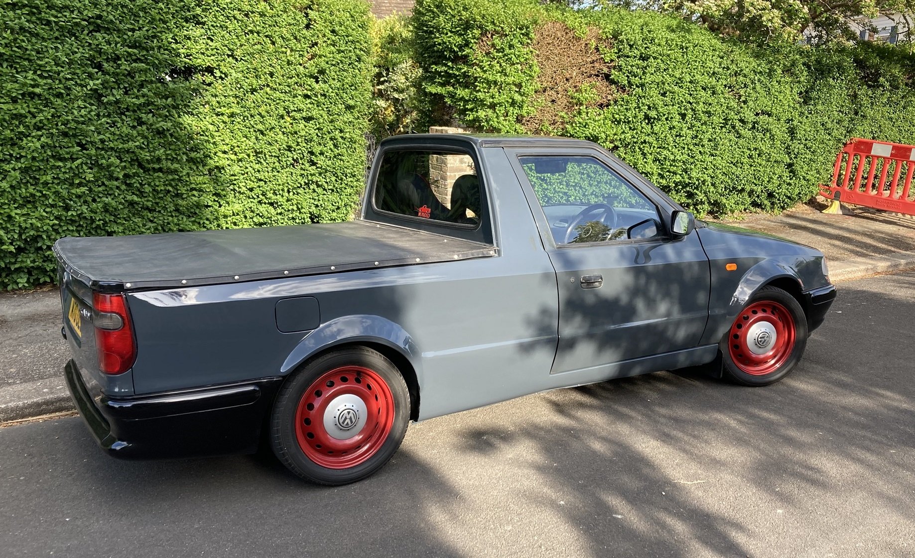
Have you got any exterior shots showing the whole car in all its glory? If so please share.
-
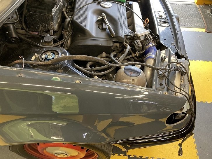
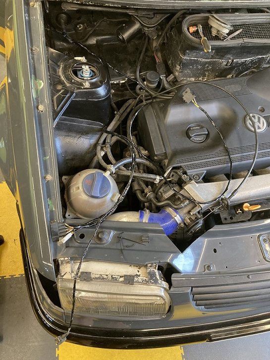
The Minor horn is likely to draw significantly more current than the puny little part it is replacing, so rather than doing a straight swap I decided to switch the Minor horn via a relay. The obvious location for this new relay is alongside the radiator cooling fan relay, which is on the bulkhead, beneath the scuttle, on the nearside between the battery and the inner wing.
Anyone who has read this thread all the way through will know that wiring is my thing, and as such I was unlikely to take the simplest route to implement the relay circuit. I have uncovered a few nasties during previous forays into the Caddy's wiring, so I thought I would probably find something else worth sorting if I had a look at the loom including the wiring to the horn, and so it proved. I disconnected the wiring from the offside headlamp unit and indicator, as well as the horn, so I could pull that section of loom to the top of the inner wing where it would be easier to get at.
This was then relieved of its wrapping tape back as far as the junction with the indicator repeater wiring. This showed me that there was a grey cable which had nowhere to go at the front corner, plus a similarly unused earth wire, and that something else had been spliced-in between the sidelight and main beam wires at some point. The unused grey wire is likely to be for foglights, which I do not have and cannot fit due to the FMIC, so this was removed, as was the stub of cable remaining from the spliced connections. This left me with some (probably fine, but unsightly) solder joints in the main beam and sidelight wires. More on these later.
The horn had been mounted on the inner wheel arch adjacent to the top mount, although the wires were wrapped within the loom all the way to the front corner, so once they were unwrapped they were plenty long enough to go across the bulkhead to the new relay coil, with no extensions required. There was easy access to a fused 12v supply for the feed side of the relay contacts, so I just had to run a new cable from the other contact terminal to the new horn, and make use of the previously unused earth connection exactly where I needed it in the loom. Things were falling nicely into place. It generally feels like that in the moments before you encounter a problem.
With the connections all made, and before I put any effort into making things look right, I re-fitted the battery and plugged-in the Minor horn. When I then pressed the horn button; nothing. A quick investigation, partly using a test lead I made from the wires previously spliced-in to the headlamp cabling, confirmed my new circuit was working fine, but the horn about which I had previously made the "not much to go wrong" statement had in fact found a way to go wrong.
I took the horn casing apart again, and this time I dismantled the little sandwich of connectors and insulators which I had previously left alone. It took me a couple of goes to work out what should be connected and what should be insulated, but then I cleaned all the contact surfaces with some emery paper and reassembled it.
Once re-connected to the pick-up, the horn now operated as it should on the push of the button. Lesson learnt, I will try to avoid tempting fate with bold statements in future.
Back to the spliced solder joints in the main beam and sidelight wires. I could have tidied these joints up, or re-insulated them with tape on the basis that they have not given any trouble up to now, but I have a few bits of Felicia/Caddy looms kicking about, so I found another offside headlamp loom, and extracted the terminals with lengths of white and green/red cable I needed to do a proper job. Once the replacement terminals were fitted into the headlamp connector, I cut the original and replacement wires and made soldered connections in the part of the loom which will be supported, and wrapped in tape. This obviously looks better, and also decreases the likelihood of these joints failing due to mechanical stress.
While the loom was unwrapped, I replaced conspicuous red insulated crimp terminals on the side indicator repeater with soldered joints, and relocated the inner wing grommet where it was supposed to be, then I re-wrapped the loom.
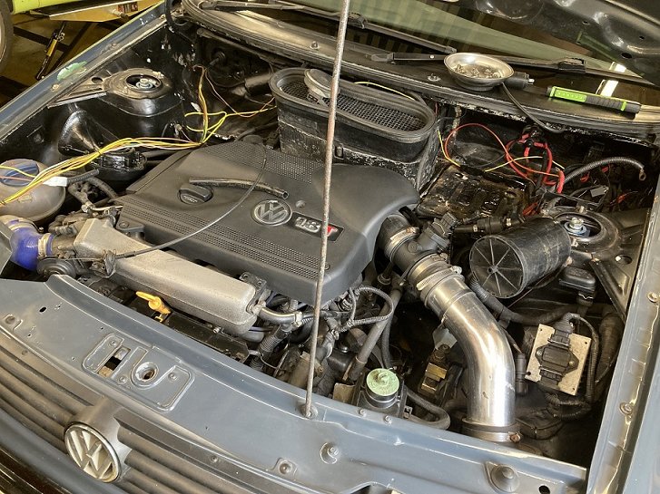
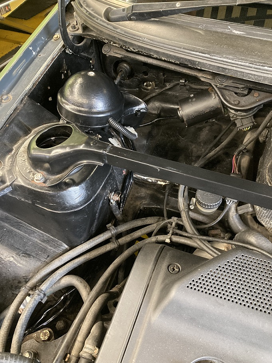
One of the jobs on my to do list for the Caddy is to shift the coolant header tank. This is currently on the offside inner wing in the front corner, as can be seen in the photo above, which means it is roughly at the same level as the cylinder head. I want to put it in the offside rear corner of the engine bay, which will allow me to make it the highest point in the cooling system, as it should be. When I do that, I will locate the Minor horn in the space at the front corner which the header tank currently occupies. The modified horn wires I have put in are for its eventual location, so I made up an extension loom reaching back to the rear corner to accommodate the temporary location for the horn fixed to the top mount / strut brace mounting bolt.
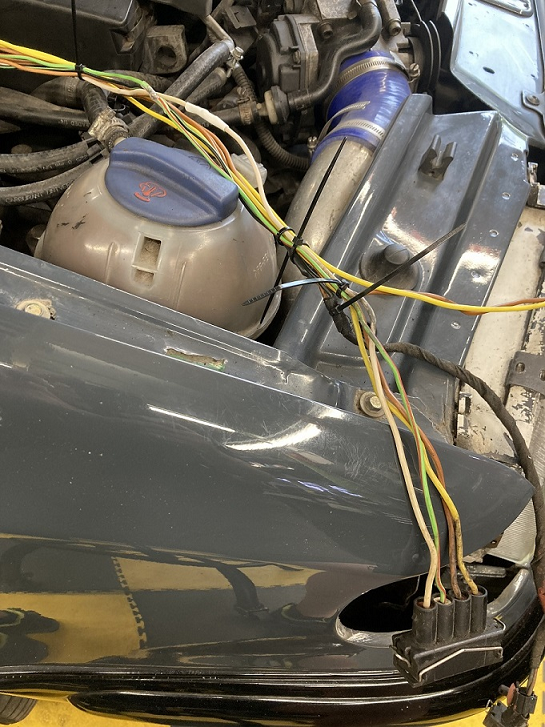
The new wiring achieves my aim of being pretty inconspicuous in the engine bay.
-
1
-
-
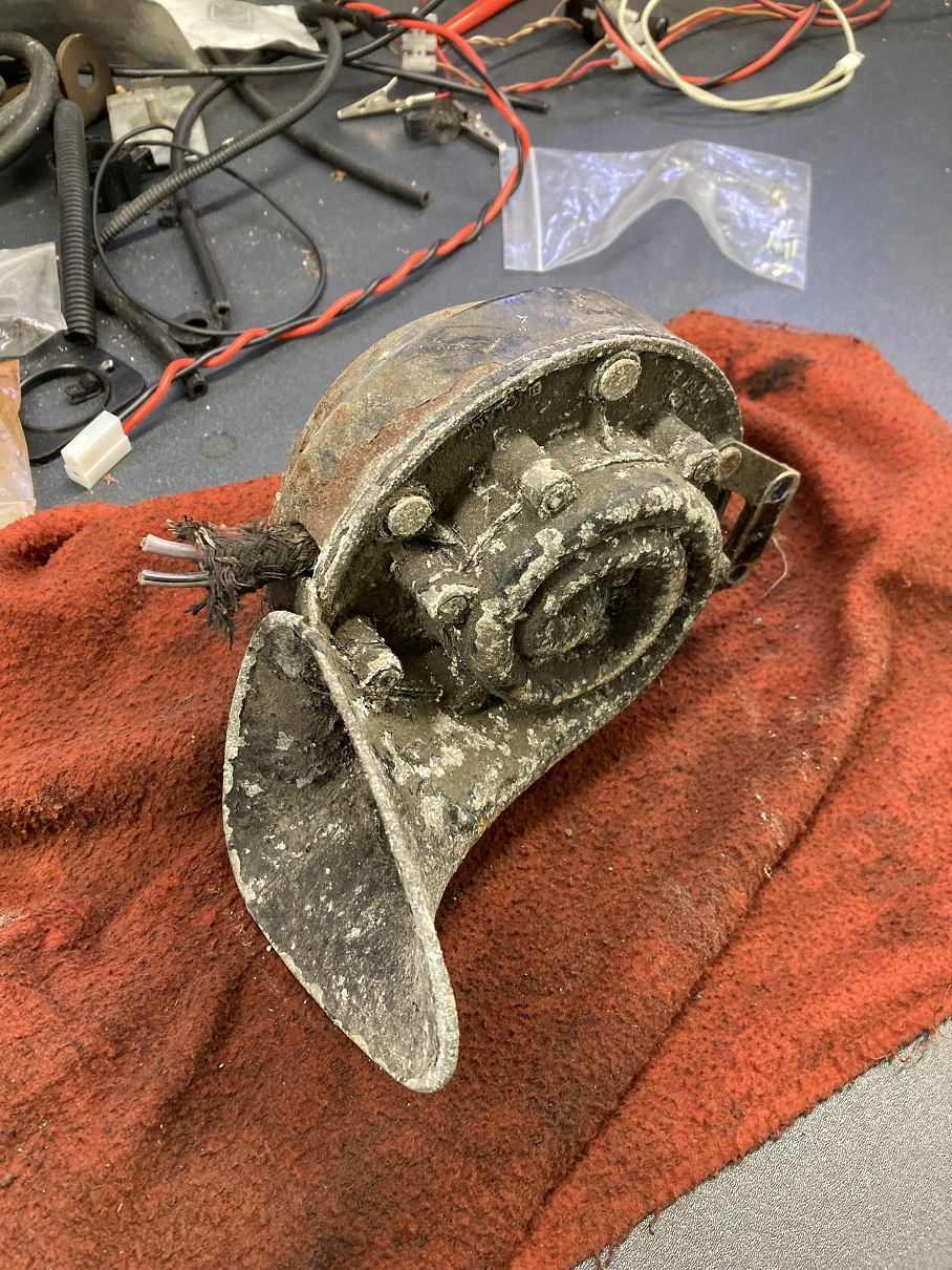
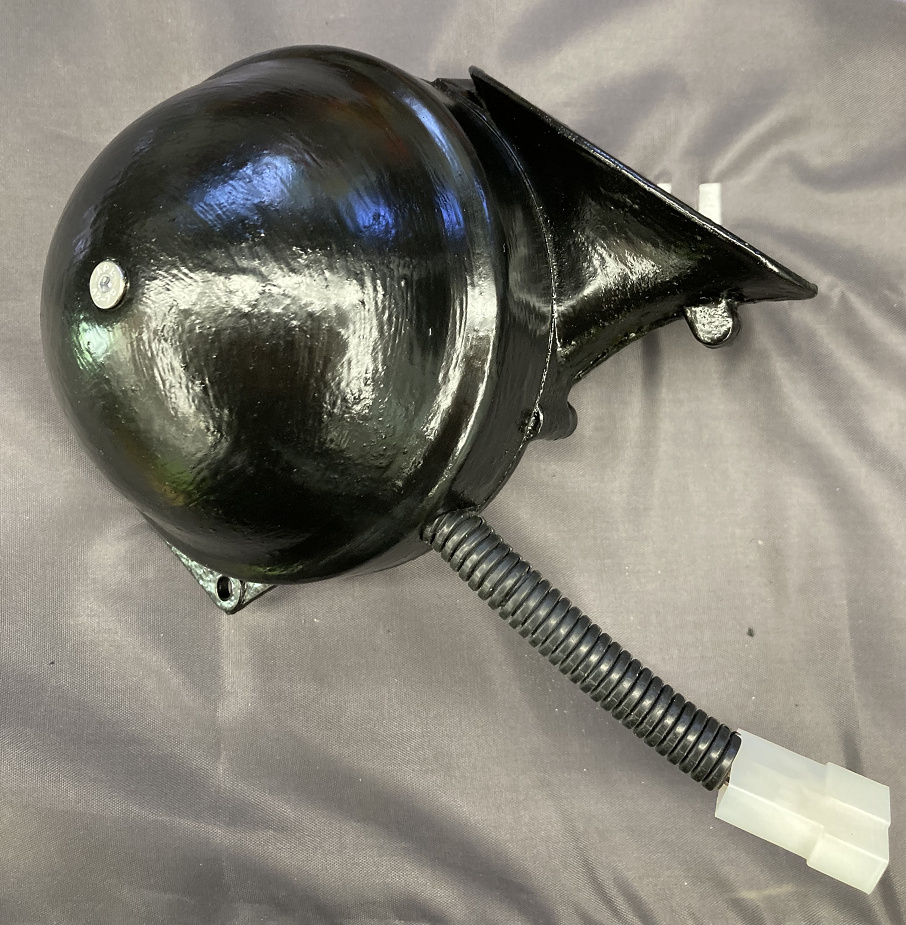
The next job started on a whim, and does nothing to improved the looks, performance, or reliability of the Caddy. In truth it could be said to be a pointless waste of time and effort, except it makes me smile, which is the whole point of this project really. My history with Morris Minors has led to something which is becoming a tradition with my builds, which is that I try to incorporate a part from a Minor into every project. On my Ibiza I use a Minor light switch for map switching, and on the Caddy I had the idea to fit a Minor horn. The horn fitted to 1950s Minors was a huge steampunk thing, with a deep, klaxon-like sound, just what the Caddy needs.
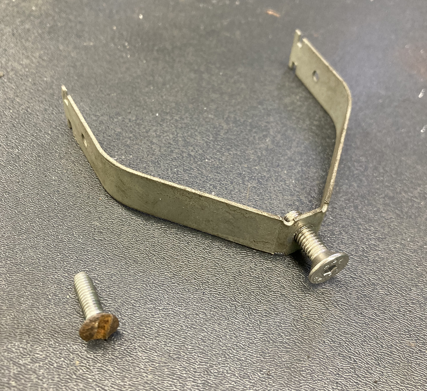
I still have a few Minor parts in my lock-up, so the next time I went over there I retrieved this.
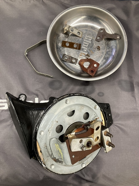
I last owned a Minor almost 20 years ago, and this horn and another had been sat in the lock-up ever since. It looked like it too. More in hope than expectation I stripped the ends of the wires and connected 12v, but my expectations were proved correct, and no sound ensued. That would have been just too easy.
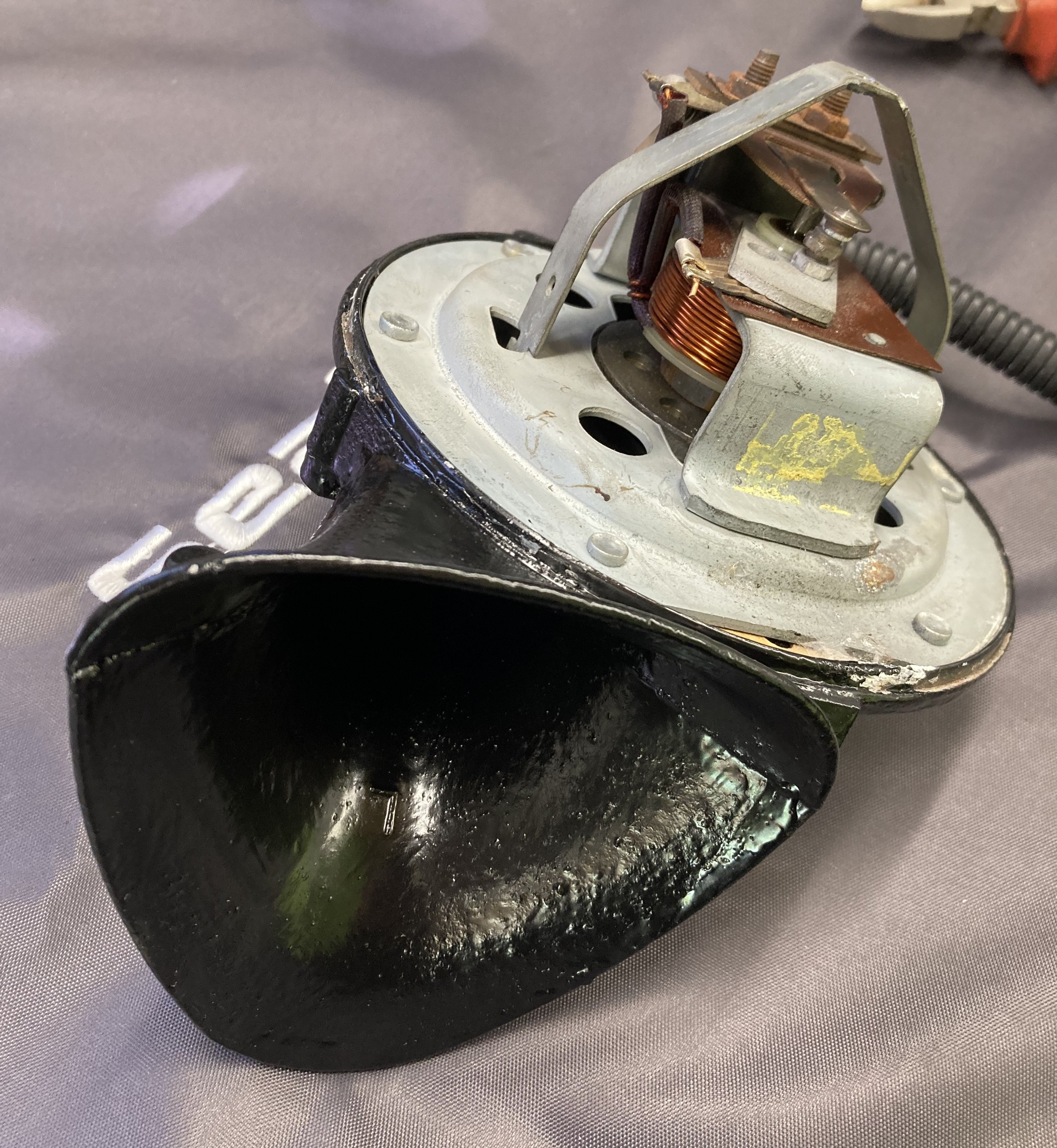
Before taking the horn apart, I gave the casing a good clean. Inside, there really is not much to go wrong. A bit of attention from some sandpaper on the contacts, followed by a drop of oil on the armature shaft, was all it took to restore function. Whilst the casing was apart it was given a couple of coats of satin black Hammerite.
The screw holding the casing together was quite rusty, as it was entitled to be having not been undone for perhaps 60 years. It was presumably a Whitworth or BA thread, and I did not have a direct replacement. Instead I drilled and re-tapped the mounting bracket with an M5 thread so that I could use a nice stainless countersunk screw.
The wiring was tidied-up with some convoluted sleeve, and a new connector, before I reassembled the casing.
-
3
-
-
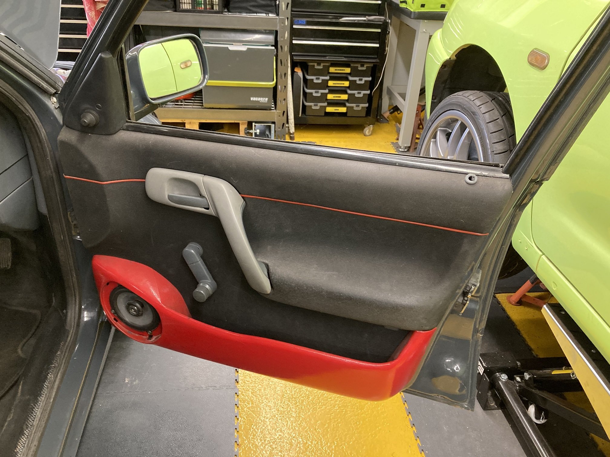
The Caddy's previous owner had applied his particular style to the interior as much as the exterior. This had resulted in a lot of the interior plastics being sprayed pillar box red. This was one of the pictures he used when it was advertised for sale.
In my ownership, all of the red parts had been replaced with standard grey, except for the door cards and door pockets. My son had been on my case to rectify this, and I could not argue that he was wrong, but there have been (many) other jobs of higher priority. However, with the Caddy due to be in the Trucks, Vans & Wagons paddock at the Retro Rides Weekender, I wanted it to look its best, so the last bit of red had to go.
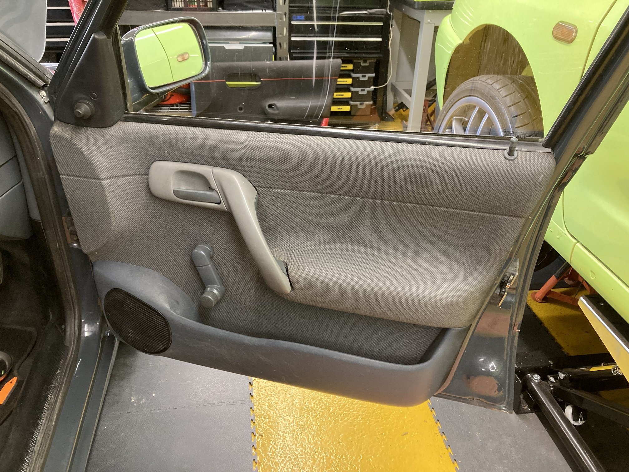
The irony is of course that it is a really straightforward job. After not managing to get round to it for years, it probably took less than 30 minutes a side to put it right. Several of the clips on the driver's side were missing or broken, but I had a few spares so not only does the door card now look miles better, but it is solidly attached too. The only frustration was that when I did the job I had not managed to find an offside grab handle in dark grey, so I had to temporarily fit a light grey one.
A few days later I retrieved a dark grey handle from my lock-up and swapped it.
-
1
-
-
13 hours ago, skomaz said:
Oops... Apologies... Entirely my fault!
Not a problem 😄
-
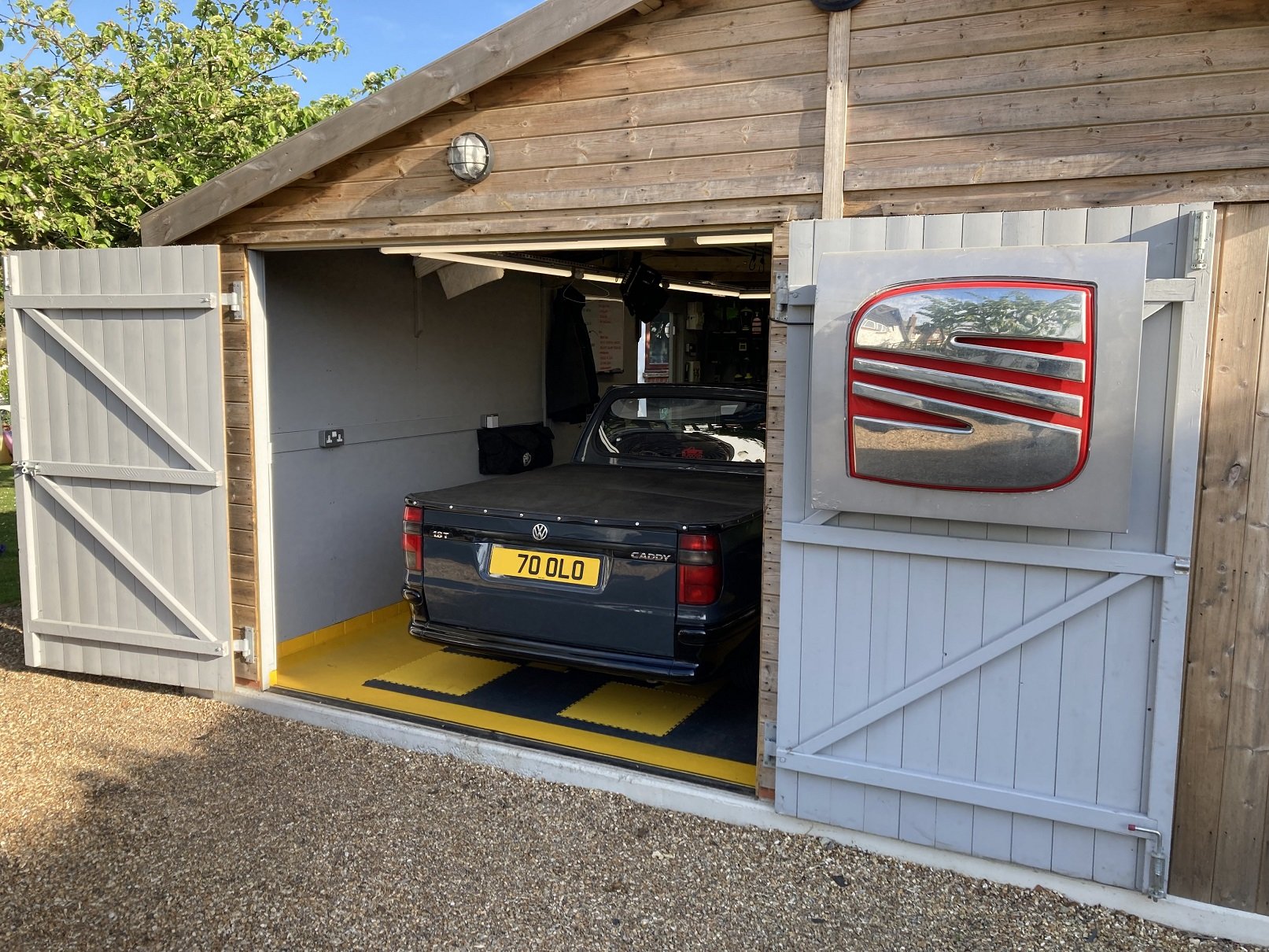
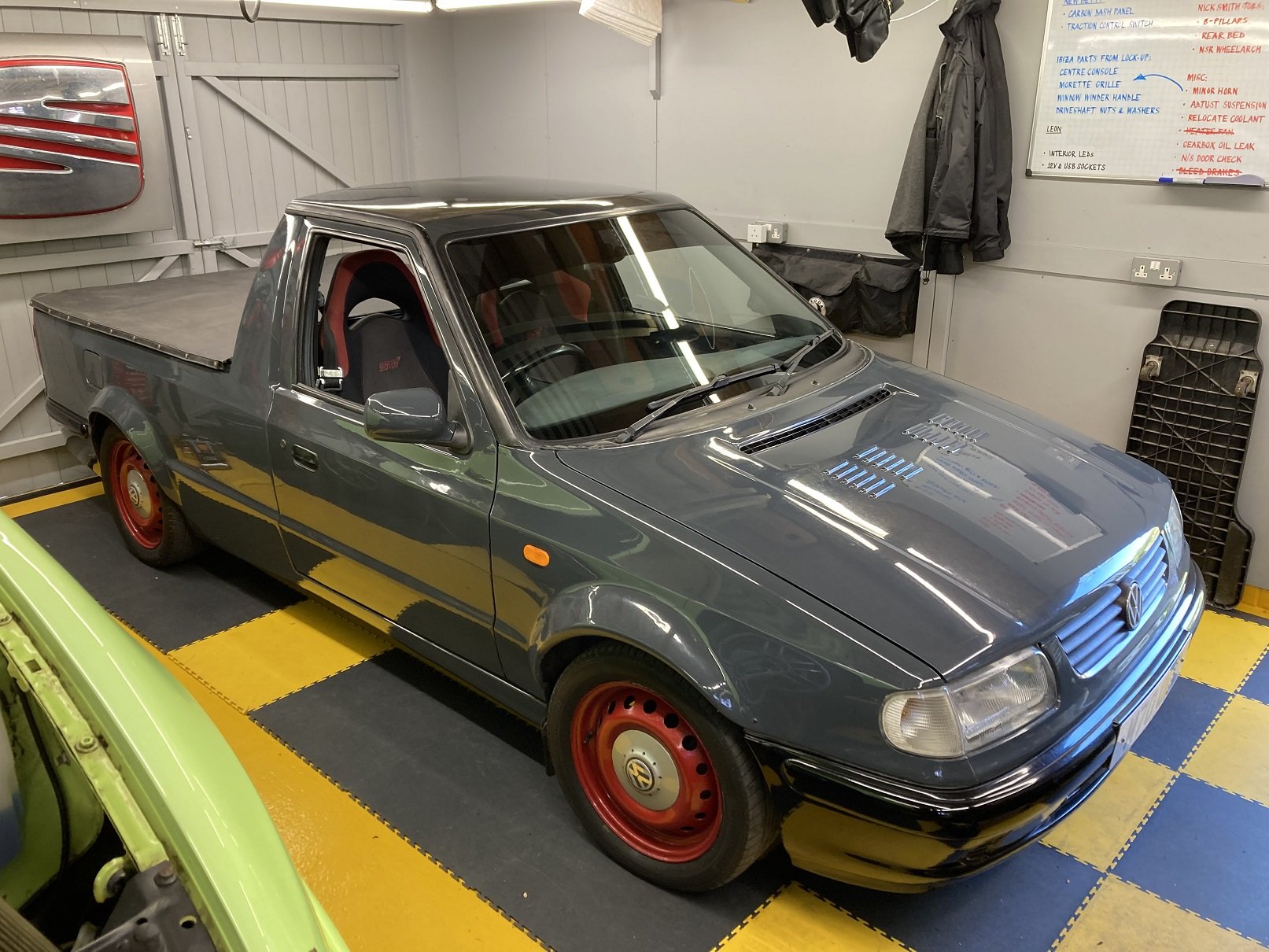
As soon as I got the Caddy home I put it away safely in the garage to keep it clean for the Retro Rides Weekender.
-
Yes "again", like I did on Friday. There was no sarcasm in my previous post, it was entirely literal, and I am not in the least bit offended by your off-topic diversion.
Thank you for your comment in appreciation of my efforts on this project.


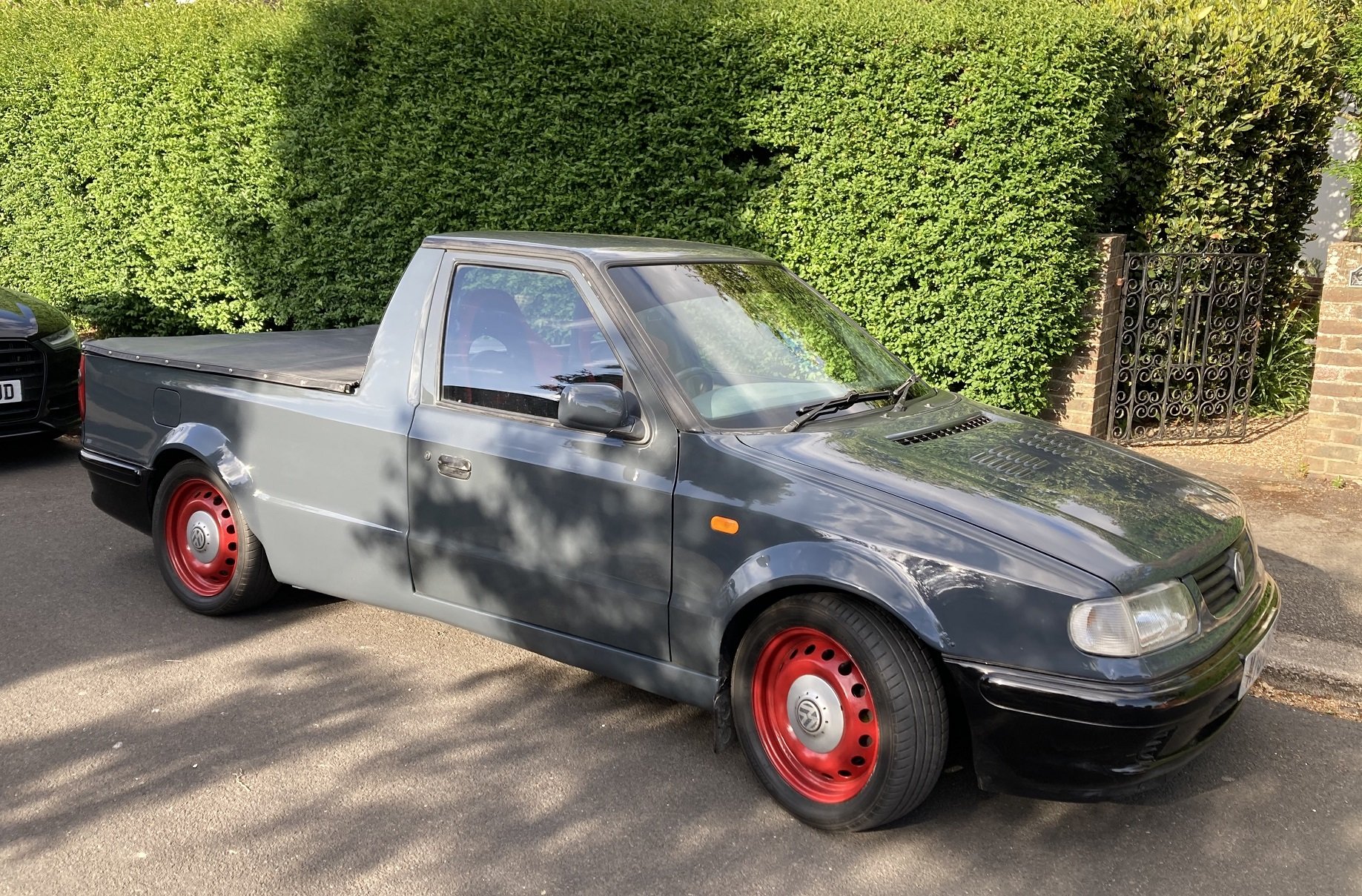
VW Caddy mk2 (Felicia) Pick-Up
in Classic SKODA Projects
Posted
The engine mountings for the Caddy have never been brilliant. Either side it has Vibra-Technics mounts which I believe to be mk4 Golf parts, and they are fine, but the third mounting has always been a bit ineffective, and it had apparently been deteriorating. When the transplant was originally done, into the Felicia, a custom rear mounting was fabricated. This bolts onto the bottom edge of the bellhousing and to a modified Felicia subframe mounting through what was described as a Mazda MX-5 track control arm bush. This bush is the orange one in the picture, and was under suspicion as it was looking tired and there was a definite clunking noise from the rear of the engine under torque. I ordered a replacement Powerflex bush, but then when I had the mounting off the Caddy it was clear that the new bush was not the right part. Nonetheless I pressed the worn bush out of the mounting, and once I had cleaned it up I could see markings saying Polybush and 27C. This confirmed it as an MX-5 front lower wishbone rear bush, so the corresponding Powerflex replacement was ordered.
After the bracket had been given a lick of paint and the new bush was pressed into place, the front half of the mounting was looking in much better shape.
The rear half of the mounting was a modified Felicia part, which had been cut and re-welded to leave it shorter than standard. I assume this was done to make the two halves of the mounting line-up straighter when fitted. I tried and failed to source a replacement bush to fit the modified bracket, so instead I bought the whole thing. I reasoned that I would fit the standard length part to see how it looked, and I would shorten it only if I could see for myself that it needed doing.
All assembled and ready to bolt into place.
It was much easier to line-up all the bolts to fit the re-bushed mounting than it ever had been to do so for the shorter version, but whether that is a good thing I am not sure. One issue I spotted when I fitted it was that that rearmost bolt, through the mounting on the subframe, was not metric. This meant that it was not as snug a fit as it should be. I found a metric bolt to replace it and it felt much more solid than it had.
The road test convinced me that the engine mounting is now in a much better state than it was before.