Jump to content

Crapula

Finding my way
  • Posts

    29
  • Joined

  • Last visited

Everything posted by Crapula

  1. Hi. I can share you de Karoq Towbar. It’s similiar. I think can help you. Accesorios - Towbar - GDW - Instrucciones de Montaje G2281.pdf Accesorios - Towbars Instrucciones de Montaje y Codificación 3DG0317_748343_SK_Karoq.pdf Accesorios - Towbar - ECS - without towbar prepared connector VW146B1SKA.pdf
  2. Hi. The rear camera of the Skoda Karoq is different from that of the Kodiaq. There are two types of Camera. The High Line with Rear View Camera with Guidance Line version. And the Low Line without Rear View Camera with Guidance Line. Karoq MY18 / 19/20 equips the LowLine version. Starting with the MY21 version, the High Line version, necessary for the Trailer Assist, will start to be installed. The High Line version also has different types of views. ·Low Line Camera (Karoq): 1 single view mode Static guide lines · High Line Camera (Kodiaq) Different points of view (trailer, battery, fisheye, ...) Dynamic guide lines It allows (with the other cameras) 360 ° view
  3. Or are you talking about OBDEleven? You need the PRO version, in order to modify encoding parameters.
  4. Sorry. I don't undersand you. What versión is the Karoq? It is an Style version, without Pack LED.
  5. 5. CODING The last step we have left is to code the switchboards of the two doors, so that the lights turn on when opening them. The coding with OBD to be performed is as follows. One per door: Driver's Door 1.- We go to CONTROL UNIT 42 Electronic driver's door 2.- Extended Encoding (Byte Mode) 3.- In Byte 1 activate bit 2 4.- we confirm Passenger’s Door 1.- CONTROL UNIT 52 Electronic passenger doors 2.- Extended Encoding (Byte Mode) 3.- In Byte 1 activate bit 2 4.- We confirm And that's it. With this we are done. I hope you like Brico. A greeting from Spain.
  6. 4. DOOR PANEL MOUNT a) If we have not already done so, we will connect the 32 Pin Connector in the control unit. We place and lower the Pink tab to ensure. b) We make sure that the Door Clips are in the Panel: These Simple Clips, which normally remain in the metal part of the Door, we will have to remove them from it, and mount them on the Panel: The Centering Clip, we will have to disassemble its central part, and place it in its Panel position: c) We will reconnect the cables in the Panel: 3 - Door opening handle 4 - Pilot Alarm / Door Close 5 - Tailgate opening button d) We reassemble the Door Panel, first fitting the Hook and the Guide Clip at the top. Once hooked on the top we fit the Clips from Top to Bottom. Finally, we can reattach the 2 torx screws. e) We connect the cables of the Window Switch / Rear View, and put it back in position: 1 - Window Winder 2 - Rearview mirror control f) To finish, we assemble the Door Handle Trim, seeing that the Staples are in place. With this we will have finished the Assembly of all the parts.
  7. c) Welcome and Warning Light Wiring. Leave the cables a little long to be able to maneuver comfortably when putting on and taking off. You can use 2 more Steal stream to make the joint. And fix the wire to the existing one, with Coroplast fabric adhesive tape: Now also, we can remove the two covers of the Catadióptrico without light and where the LOGO light will go, on the door panel. You just have to tighten the eyelashes.
  8. 3. CONNECTIONS AND WIRING The connection of the Lights is carried out at two points, of the Clema B of the Door Control Unit J386. According to the Scheme: The first in a Free Pin (Positive), and the second stealing the brown wire (Ground. Pin already busy). a) POSITIVE – PIN 16 - T32b The first thing we have to do is disconnect Connector B from the Door Control Unit. The 32-pin connector. Ref: 1J0972977D To do this, press Tab 1, and lift the Pink tab in direction 2. Once disconnected, we have to remove the white inner sleeve with the harness, tightening the two dots (in Red) or raising the tongue, and pulling in the indicated direction: Now we will have to grind a wire with one of the metal pins. If you have Crimper better, ... if not with the tongs. This connector, we must enter it in PIN 16 of the T32b b) MASS (LAND) – PIN 5 - T32b This PIN is already busy ... So we will have to steal Brown cable connection, which goes to that Pin. For this we connect the second cable to the brown one. I advise therefore, use a Steal stream.
  9. 2. UNPLUG THE PANEL ELECTRICAL AND MECHANICAL CABLES Now, holding the Panel in the air, we will have to disconnect a few cables. 1.- Power Window Connector – Ref.5C0971974: To disconnect it you have to lift the red tab. 2.- Rearview Mirror Control Connector - 6Q0972706A: To release it, press the side tab. 3.- Cable to mechanically open the door: To release it, it is necessary to move the tongue 1, and then remove the plastic part 2, from the Guide. Finally we unhook the head of Cable 3. 4.- Pilot connector alarm / closing - 1J0973119 - 1J0973332: To release it, press the side tab. Note: In the first photo, the whole set is shown. You can also remove everything. 5.- Connector Opening button Tailgate - 1K0972704C: To release it, press the side tab. ... With this we will have the Door Panel Completely disengaged and we can remove it.
  10. d) Now we only have to unhook the Panel of the clips that have been prying between the sheet and the door molding. We will follow the next scheme: Watch out! When unhooking the Panel, we will find some cables between the Body of the Door and this. We must unhook it carefully, trying not to tear the cables (there is a certain slack). We have to start at the bottom left, and go unlocking the clips according to the numbers (Blue). Once all the lower and lateral Clips are unlocked, we can lift the Door Panel (Purple) upwards, to remove it from its upper part of the Hook and the Guide Clip. The different Clips are these so you can see that you are releasing: Clips Simples (Ref. 5J0867276): Clips Centrador (Ref. 4H0867260): These Clips, when dismantling the Panel, many will remain in the metallic part of the Door. In the ASSEMBLY section, it is explained later that those that have remained in the door must be removed and placed on the panel so that it can be anchored.
  11. Important! Before you start, open the window and turn off the ignition of the car. Now we will explain the steps to follow for the entire operation, using the Duct Door. The passenger door will be the same, with some connector less. 1. DOOR PANEL DISASSEMBLY In order to access the disassembly of the Door Panel, certain steps must be followed, following the parts scheme: Disassembly must be done with some care, but in some places vigorously. I recommend using the plastic levers to pry the pieces and disassemble clips. a) The first thing we will have to disassemble is the Door Handle Trim (8). Ref: 57A867197 / 57A867198 This piece is placed under pressure, with a series of staples, some lateral tabs, and a final tongue. Careful! Lateral tabs are very susceptible to breaking. The best way to remove it is by starting to pry through the upper center (point 2), trying to unhook the lateral tabs, ... then through the lower center (point 1) and once disengaged, lift the end (3), and pull on its direction. b) Then we have to disassemble the Window Switch and Rearview Control, to access the cover screw (10). Refs: 57B867171 / 57C867172 To remove this element you have to pry, starting at the back. On the back, it has two tabs, simple to disengage, ... The front is more difficult, since access is somewhat more complicated. It also has two tabs to disengage. We just need that, lift the rear area to access the screw behind it. If you can't get it out, do it like this. This element has two electrical connectors that we can disconnect if we want. (See info in the Electrical Connections section Connectors 1 and 2). c) The next step is to remove the only two screws that the Door Panel carries. They are 2 Torx M6x20 Screws (6). Ref: N91096801
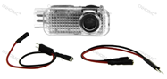
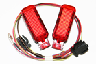
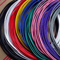
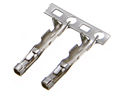
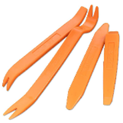
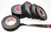
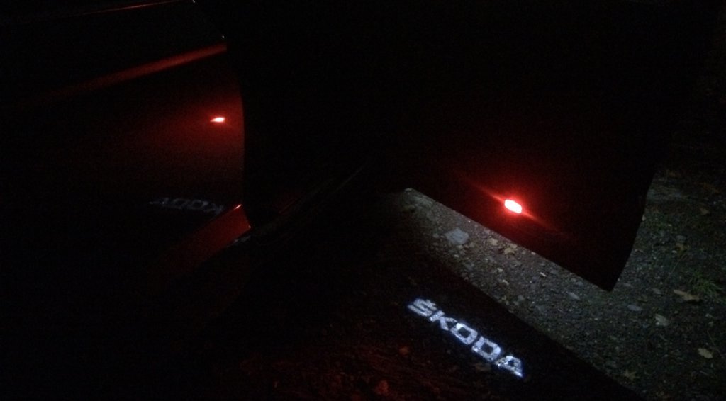
  12. Now we will explain step by step how to install the Led Welcome Lights (Logo Skoda), and the Red Emergency Lights of the Front Doors. INDEX: 0. MATERIALS 1. DISASSEMBLY OF THE DOOR PANEL 2. UNPLUG THE PANEL ELECTRICAL AND MECHANICAL CABLES 3. CONNECTIONS AND WIRING 4. MOUNTING THE DOOR PANEL 5. CODING ___________________________________________ 0. MATERIALS • Welcome Lights (Logo Skoda) LED: 7,36€ Link • Warning Lights (Red): 7,00€ Link • Connection Cable (about 5 m😞 7,82€ We can use a Cable 0.5mm (24AWG) o 0.65mm (22AWG) • 2 Connection pins for Door Switchboard ConnectorT32b “000979009E”: 2,08€ I recommend taking a kit of these to ensure that the pins are of the correct diameter: Link • Plastic Tools: 1,39€ OPTIONAL • Steal current connectors: 1,53€ Link • Tesa Coroplast fabric adhesive tape for wiring: 1,43€ Link • • Buckle closure clip (Should not be necessary. Only ifbroken): 2,61€ (5uds) Link
  13. Yes, I'm working with this. It was in case you had the concrete Karoq, to know if there were any differences.
  14. Sensational @Arkaig
  15. Fantástico de nuevo, @Arkaig con los manuales de taller de Yeti. ¿Podrías obtener los diagramas de cableado completos de Karoq? gracias amigo
  16. A5 AdapMap Adaptations: Identification signals traffic mode fusion: Fusion of road signs Adaptation_tsr: Par_country_mode: Automatic Par_relevance_mode: enabled Par_country_code_RSR: 0 Par_country_code_VZF: 0 Deactivate production mode: deactivate Calibration destination positions: Target 1, calibration mark 1, coordinates x: 2610 mm Target 1, calibration mark 1, coordinates and: 824 mm Target 1, calibration mark 1, z coordinates: 1732 mm Target 1, calibration mark 2, coordinates x: 2600 mm Target 1, calibration mark 2, coordinates and: -824 mm Target 1, calibration mark 2, z coordinates: 1732 mm Target 1, calibration mark 3, coordinates x: 2600 mm Target 1, calibration mark 3, coordinates and: 825 mm Target 1, calibration mark 3, coordinates z: 1075 mm Target 1, calibration mark 4, coordinates x: 2600 mm Target 1, calibration mark 4, coordinates and: -825 mm Target 1, calibration mark 4, coordinates z: 1075 mm BAP customization: Ativado Body height edge of the wheel arch: Height of the car edge of the housing. of the wheel, of. left: 766 mm Car height edge of the housing. of the wheel, of. der .: 767 mm Height of the car edge of the housing. of the wheel, of. left: 763 mm Height of the car edge of the housing. of the wheel, after. der .: 767 mm Assist Lane departure notice, lim. speed with trailer: 300 km / h standstill_mode: not activated Warning intensity. Lane change assistant: Medium Activation and deactivation of all development messages: Activation_of_development_messages_reserved: not activated Activation_of_development_messages_lane: not activated Activation_of_development_messages_WLA: not activated Activation_of_development_messages_VZF / TSR: not activated Activation_of_development_messages_EHR: not activated Activation_of_development_messages_HCA_lane: not activated Activation_of_development_messages_HCA_state: not activated Activation_of_development_messages_internal: not activated Xcp_interface: not activated Mask_error_reactions_for_development: not activated Initial calibration, result: Pitch angle: -0.268 ° Yaw angle: 0.417 ° Rolling angle: -0.028 ° Camera height: 1475 mm Mode of production: deactivate Mode for roller test bench, functional: not activated Customize interv. moment with terminal 15 on: Last adjustment Distance with the calibration field: 1500 mm Shaft separations: Front axle transverse position: -0 mm Transverse position rear axle: 0 mm Activation status of lane change: on (setting by menu) Masked_fault_classes: 255 255 255 255 WLA_adjustment: BrightnessThreshold_active: 0 BrightnessThreshold_passive: 0
  17. Did you reset the MMI? Of Course: UC44: 01 00 00 11 00 C0 01 10 - Against steering wheel - activated - Parking assistance system for parking - Inactive - Slope Compensation - Not activated - Lane departure warning system - Activated - Steering wheel steering angle transmitter - Message_sent - Hybrid traction - Unassembled - Rampenverhalten bei Motorstopp - slowly - Driver profile selection - Active - Electronic stability program - Activated - Engine start by power steering - activated - Gierratenabhängige Mittenverschiebung - inactive - active with motor stop - activated - Assistance_system_monitor - activated
  18. Hi @Tezaman My karoq carries the factory Lane Assist My A5 coding is (and our differences): Byte: 00 01 02 03 04 05 06 07 08 09 10 11 12 13 14 15 16 17 18 19 20 21 Crapula: '02 03 07 08 00 00 04 01 00 22 13 44 81 50 A9 00 84 00 0E 20 00 20 Tezaman: '00 04 08 02 00 00 04 01 00 22 13 45 80 50 A1 00 10 00 0E 01 00 20 Byte 00: Value 02 LC, 00.0 ~ 7.00, Manufacturer: Volkswagen LC, 00.0 ~ 7.01, Manufacturer: Volkswagen_N LC, 00.0 ~ 7.02, Manufacturer: Skoda LC, 00.0 ~ 7, 03, Manufacturer: Seat LC, 00.0 ~ 7.04, Manufacturer: Audi LC, 00.0 ~ 7.05, Manufacturer: Bentley LC, 00.0 ~ 7.06, Manufacturer: Lamborghini LC, 00.0 ~ 7.07, Manufacturer: Bugatti LC, 00.0 ~ 7.08, Manufacturer: Porshe LC, 00.0 ~ 7.09, Manufacturer: Quattro LC, 00.0 ~ 7, FF, Manufacturer: Uncoded Byte 01: Value 03 LC, 01.0 ~ 7.00, clase: A000 LC, 01.0 ~ 7.01, clase: A00 LC, 01.0 ~ 7.02, clase: A0 LC, 01.0 ~ 7.03, clase: A LC, 01.0 ~ 7.04, Clase: B LC, 01.0 ~ 7.05, Clase: C LC, 01.0 ~ 7.06, Clase: D LC, 01.0 ~ 7.07, Clase : E LC, 01.0 ~ 7.08, Clase: E + LC, 01.0 ~ 7.09, Clase: Other class LC, 01.0 ~ 7, FF, Clase: Uncoded Byte 02: Value 07 LC, 02.0 ~ 7.00, Generation: Not coded LC, 02.0 ~ 7.01, Generation: Generation 1 LC, 02.0 ~ 7.02, Generation: Generation 2 LC, 02.0 ~ 7.03, Generation: Generation 3 LC, 02, 0 ~ 7.04, Generation: Generation 4 LC, 02.0 ~ 7.05, Generation: Generation 5 LC, 02.0 ~ 7.06, Generation: Generation 6 LC, 02.0 ~ 7.07, Generation: Generation 7 LC, 02.0 ~ 7.08, Generation: Generation 8 LC, 02.0 ~ 7.09, Generation: Generation 9 Byte 03: Value 08 LC, 03.0 ~ 7.00, Body type: Sportback LC, 03.0 ~ 7.01, body type: Sedan LC, 03.0 ~ 7.02, body type: Wagon LC, 03.0 ~ 7.03, body type: Hatchback LC, 03.0 ~ 7.04, body type: Coupe LC, 03.0 ~ 7.05, body type: cabriolet LC, 03.0 ~ 7.06, body type: Crossover LC, 03.0 ~ 7.07, body type: pickup LC, 03.0 ~ 7, 08, Body type: Minivan LC, 03.0 ~ 7.09, Body type: Other type LC, 03.0 ~ 7, FF, Body type: Not coded Byte 09: Value 22 LC, 09.1 ~ 4.01, Thermal glass LC, 09.1 ~ 4.02, type of windshield: thermal (green) glass LC, 09.1 ~ 4.04, windshield type: clear glass LC, 09.1 ~ 4.06, type of windscreen: Aterial (purple) glass LC, 09.5, Active - Right traffic LC, 09.5, Not Active - circulation on the left (England) (Maybe for you) LC, 09.6, Steering side LC, 09.7, Steering translation Byte 11: Value 44 LC 11.0.00, ??? installed/not trailer detector electronics (AAG) LC, 11.1.01, set lane change assistant (LCA / Side Assist) LC, 11.2,04, adaptive cruise control obtain (ACC) LC, 11.3.08, Pedestrian Break LC, 11.4.10, Blind Spot Detection LC, 11.5.20, Start stop control LC, 11.6.40, Rain / light sensor coded LC, 11.7.80, Windshild heater Byte 11: Value 81 LC, 12.1.00, Main Unit Not Enabled LC, 12.1.01, Main Unit Enabled ... LC, 12.6, Parking assistance installed (PLA) LC, 12.7.80, Installed stability program (ESP) Byte 14: Value A9 LC, 14.0 01, Direct CAN interface for ACC radar included LC, 14.3 08, Perso HC last Setting LC, 14.5 ~ 7.00, Interception time Body: Early LC, 14.5 ~ 7.40, Intervention time: Early Early LC, 14.5 ~ 7.40, Intervention time: Late LC, 14.5 ~ 7.80, Intervention time: Early (Control via MFA +) LC, 14.5 ~ 7, A0, Intervention time: Late (Control by MFA +) Byte 16: Value 84 LC, 16.0, Lane Assist_AGW_output LC, 16.1, Lane Assist OFF text LC, 16.2 ~ 3, 04, EA_Variant2 LC, 16.2 ~ 3.08, Emergency assistance: Option 2 LC, 16.4, Recognition of traffic signals enabled (TSR / VZE) LC, 16.5, STA LC, 16.6, Headin Control assist Mobility (HCA) LC, 16.7, Headin Control assist (HCA / Lane Assistance) Byte 19: Value 20 LC, 19.0 ~ 3.00, Additional headlights not installed LC, 19.0 ~ 3.01, Additional headlamps (FLA): halogen LC, 19.0 ~ 3.02, complementary high beam lamps (FLA): Xenon LC, 19.0 ~ 3.03, complementary high beam lamps (FLA): LED LC, 19.0 ~ 3, 04, Additional headlamps (FLA): Laser LC, 19.4 ~ 7.00, Type of headlamps (FLA): Halogen LC, 19.4 ~ 7.10, Type of headlamps (FLA): Xenon LC, 19.4 ~ 7.20, type of headlight (FLA): LED LC, 19.4 ~ 7.30, type of headlight (FLA): LED with variable light distribution Regards
  19. Too many unknowns. If you installed the A5 sensor, it may be a calibration problem. But perhaps without the serial camera, some other component is needed in a higher version, ... like the BCM might need one (Medium Plus - BCM MQBAB M +) or (High - BCM MQBAB H). What model do you equip? We do not have experiences with retrofits of the A5 sensor, only with activation with the Traffic Assist as standard. Another thing, you said "Something else that i want to note is the 44 Power steering module when i entered longcode helper for the 44 module, there was an warning poped that saying i will have no longcode help, so i dint have any info displayed for every bit, i just followed the instruction and into Byte 3, checked activate bit 5. " But the process indicates "byte 3, activate bit 0" in the "44 Powe r steering module", ... Is it a typing error? Maybe we could compare the encoding with a Log of yours.
  20. If you made a Retrofit, how did you code the A5 Control Unit? I suppose you've followed some coding process for the Lane Assist, right? which has it been? What message does it appear when it does not work? ps: Do you have Park Assistant?
  21. You can ask me here if you wish.
  22. I'm glad that the information from our Spanish forum was good for you.
  23. Fantastic @Arkaig Thank you very much Will not you have the Electrical Flow Diagrams?
×
×
  • Create New...

Important Information

Welcome to BRISKODA. Please note the following important links Terms of Use. We have a comprehensive Privacy Policy. We have placed cookies on your device to help make this website better. You can adjust your cookie settings, otherwise we'll assume you're okay to continue.