R_U_AFA
Members
-
Joined
-
Last visited
Everything posted by R_U_AFA
-
R_U_AFA replied to sebbofelicia1's topic in Skoda Favorit, Skoda Felicia, Skoda Fun and Skoda FormanSo would the vanplus have dampers with more reistance to account for expected increased payload OR would they have less resistance to make for a smother ride and compensate for stiffer springs.
-
R_U_AFA replied to sebbofelicia1's topic in Skoda Favorit, Skoda Felicia, Skoda Fun and Skoda FormanWould the vanplus have dampers with more or less reistance to account for the increased spring stiffness
-
I was meaning just the tank, not the whole fuel system. If anything would be different I think it would be the diameter of the sender unit apature. If it did fit, It should increase fuel capacity from around 42liters to 47liters, giving about 50 miles extra, from a full tank of fuel, for fuel injection engines. Just seeing if someone else had done it, to see if it was possible, and to gauge how hard / easy a job it would be. I think the hardest part would be sourcing a fuel tank from a carburettor model.
-
I don't know if anyone already done this? But can the fuel tank from a carburettor system favorit/felicia, be fitted to a fuel injection system favorit/felicia, to increase overall fuel capacity? It looks like it is a straight swap with just a few modifications to fuel lines, relocation of fuel filter,and change the fuel level sender/(fuel pump-on injection engines) Looks like carburettor fuel tanks are rare though.
-
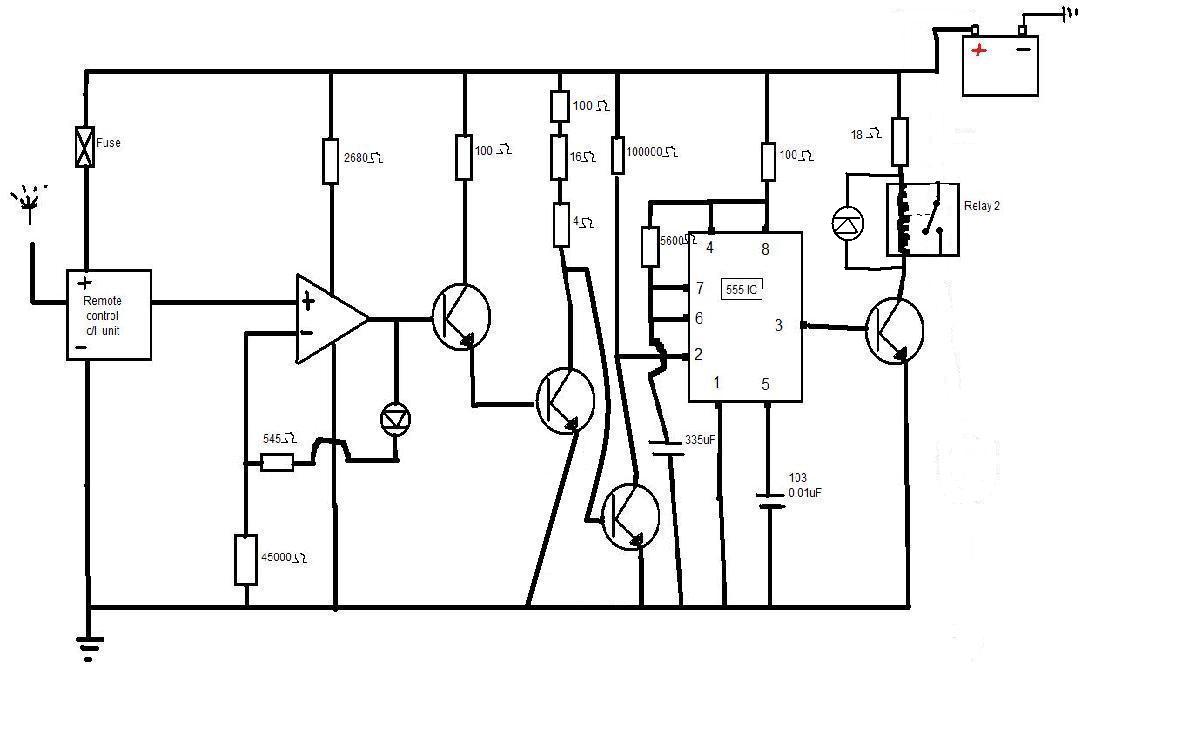
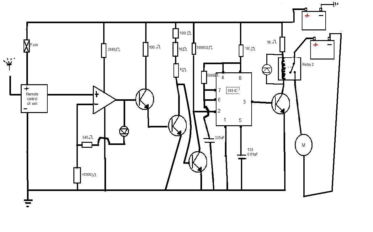
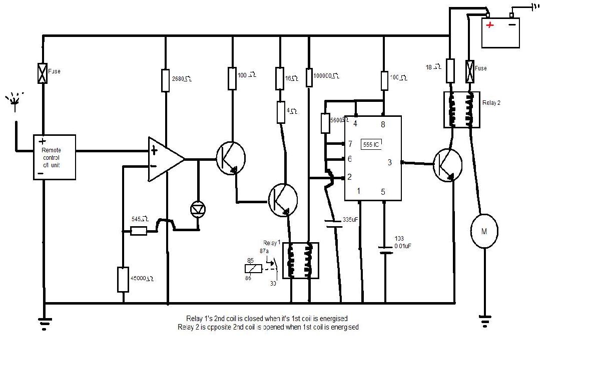
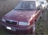
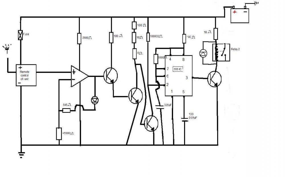
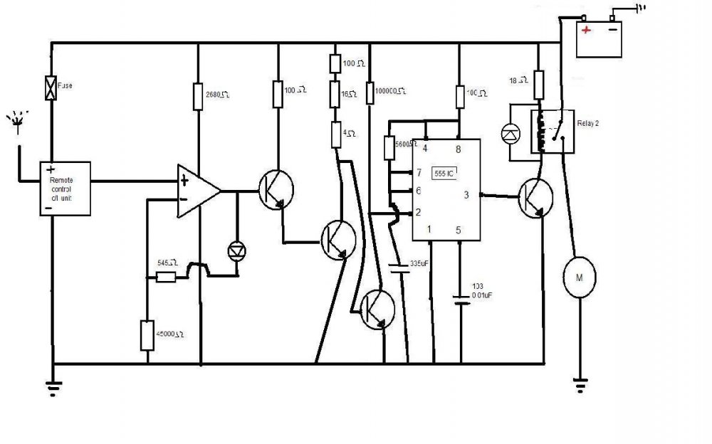
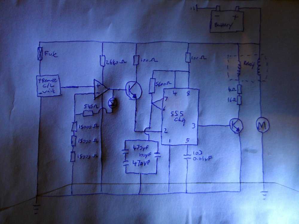
So this project has been on the backbench for a while, But I got back to it today: The circuit has been modified again with a transistor NOT gate added in place of relay 1, and I have it working pretty much as it should, as many times as I want, when no load is placed on the relay(relay switches on off as it shoud) as shown in first diagram below. But now a new problem seems to have raised its head, that when a load is connected to the relay(as in the 2nd circuit diagram) and the pulse is sent, the c/l control unit goes quiet/stops working when the relay switches. The circuit does work, but just once, because the control unit is now off, and no further pulses can be sent. It is almost as if the control unit power is removed/bypassed or goes too low, when relay switches. Now I am sure that there is an obvious fundamental principle of electronics that I am missing here, or a reason that this is happening. N. B. I also tryed a different way as shown in the 3rd diagram using a seperate battery, and it works perfectly every time, but of cause I can't add an extra battery to the car to solve this problem.

-
Ok, I did not know you could get them seperate, just presumed that it was molded to the hose in the manufacture process.
-
Has anyone fitted hel preformance stainless steel brake hoses (part:SKO-4-010) I have no doubt they will fit, but just wondering if they still have the rubber stopper halfway down that keeps the pipe away from the car body. I'm not really botherd about any preformance gain, I just like the lifetime warrenty aspect.
-
It was the caliper piston, it's condtion was ok, just stiff on returning (It was lubricated mabey just not enough) Didn't have any silicon grease, so used a few drops of brake fluid, still I had to push it in and pump it out 8 or 9 times to get it to stop locking the discs. I suppose it's to be expected as seen as it won't have had any extra lubrication since leaving the factory. I'll have to keep an eye on the other caliper as well. Fixes that are free are the best.
-
I Did the guide pins today, so it's not them. I didn't remove the dust seal and check the pistons condition (I can check tommorrow), but the piston does seem to have free travel It's almost like the fluid pressure is not being released when the brake peddel is.
-
So yesterday I took the car for about a 2 mile trip and I noticed that the front left brake is nearly fully seized on (the car did drive but the brake got extreamly hot) So today I had a look at the brake caliper and the disc was locked in place. There are no visiable leaks to the caliper. So to start with I applied anti-seize to the guide pins, and pushed the caliper piston back into its bore, and the caliper slides freely, and disc rotates. But when the brake pedel is applied and the free play taken up after a few pumps, the disc is again unable to be rotated by hand. I will also point out the car has been sat unused for around a month now. And just before that I had applied anti seize to the pads to stop them squealing. Anyone got any sugestions to how to diagnose which part is at fault and may need referbishing/replacing? I don't just want to be replacing parts at random.
-
So compleated the test in the previous post, and results are not as expected: 1. Volts with remote idle = 6V but 2. Volts with remote active = 6V (I am wondering if something has been damaged internally, because I have measured current previously)
-
Sorry got the relays the wrong way around Relay 1's 30 to 87a pathway is open when 85 86 energised relay 2 is oposite motor circuit is closed when energised(allowing the motor to run)
-
So I have been messing about again today and took some of your advice on board, and GOOD NEWS I have got the circuit working pretty close to how I want it (but only tryed it out a few times) You will see from the sketch below, I have modified the circuit again with a extra relay, and now the 555 side looks a lot like the 1st diagram I uploaded to start with. I am still using the rather convoluted RC arrangement from earler although not shown it in the sketch below(mabey something to work on there) and the timing is a bit out around 0.1 seconds too long (I am guessing that could be due to issues mentioned in your earler post about tolerances) Xman I can still answer the questions above if you want to point out a better way to do it/where I have gone Wrong
-
Only just seen your edit xman The trigger return voltage at pin 2 is boarderline (72% of 12V 8.64V) but if (72% of 12.5V = 9V) Would it be posiable to use a voltage divider to bring down the supply voltage? I will have to do some more measurments tommorow
-
Here is the circuit exactly as I had it today(but withot the motor connected) Both transistors are bipolar NPN transistors BC547B The input trigger High is 9V 28mA constant, The input trigger low I will measure tomorrow and update(I seem to remember it is somewhere near Zero for 1.8 seconds) There is also a fuse on the motor side of the relay have forgot to draw
-
To start off with I will just say thanks for your help. I will upload sketch circuit in a few mins To expand more I will start at the very begining So my car has c/l but only on the key, so decided to upgrade to remote c/l and got one of the readly available aftermarket kits online. I have had no problems intergrating this with the cars current c/l when on a test fitting. It was after this that I noticed the optinal remote boot release optinon like on most new cars, and I thought it would be as simple as a few more wires and a selonoid (late model felicia's already have a manual boot release mechenisim in place to work with) Now this is where the problems start; the springs in the current manual release mechenisim are too strong for selonoid to actuate, and with limited space avaliable my only option was a motor with a small arm to gain some leverage. So still should be quite simple, a relay driven by the pulse emmited from the remote c/l unit. No not that simple the pulse form the unit is pitifully small somewhere around 25mV and 2mA for 1.8 seconds Again this can be worked around using an op-amp as an amplyfier to trigger a transistor witch triggers a relay (it took up a lot of time working this circuit out) I will include this in my sketch Now this is the problem solved you would think, but again No operating the motor for 1.8seconds can leave the boot release mechenism in the unlocked posison and the boot being unlatched. Now this could be solved by pressing the key fob's boot relese button untill the boot mechensim is latched again, but roughly speaking the mechensim would land in unlatched posison 25% of the time. So I figured by using a 555 chip I could have the motor always end in a place that leaves the boot latched (2.05seconds leaves the motor in the same place every time, a park posision if you will) Now with the back story over lets continue.... There is quite a lot to take away from your posts, there seems to be quite a few mistakes I have made Lets start simple, with the term float. Yes, the trigger must not float can you elaberate a bit more? Also you say Supply voltages to ICs should always be stable and (capacitor) decoupled to ensure correct operation. So am I missing some capacitors, and does the 100ohm resistor need to go? I understand that the capacitor setup I have is silly, but I was trying to make up the correct capacitance for the timing with the bits I have. Would you suggest a higher value resistor and lower value capacitor?
-
Also I am sourcing the output
-
Which of the 2 circuits that you put in your first post have you built? The 2nd one that has been editied Can you please explain exactly what you want the circuit to output in therms of of high and low states and timings from startup? High state: Enough to switch on a transistor, probably anywhere above 2v and 100mA Low state: As close to 0v as possiable Timed pulse of 2.05 seconds after pin 2 goes low What are you using to check the output? Nothing, just the internal resistance of the tranistors base-emitter path Are you keepimg the output current below 200mA? Sorry, don't know, didn't measure that Does the chip get hot when it is running? No
-
So A few problems today I created circuit as shown above (except now with a 100ohm current limiting resistor) Using 5600ohm resistor at R1 and 335uF capacitance at C1(made from 2x 470uF in series and 100uF in parallel with them) As far a the time caculation as I understand It is: Time = 1.1xR1xC1 SO Time= 1.1 x 5600x 0.000335 witch equals 2.0636 seconds (close enough to the 2.05 I want) But what did happen was 1. circuit stars stable no output at pin 3 (OK) 2. drop current at pin 2 output at 3 goes high (OK) And this is where the problem is, one of the following is happening, I'm not sure which 3a. output at 3 stays high and doen't return to low even after 5 mins (should return to low after 2.05 s, and stay low) OR 3b. output at pin 3 goes high low repeatedly as to seem like a constant flow, and still does'nt return to a stable state (? shouldn't happen pins 6 & 7 connected together) Is there something here I have wrong?
-
Right, Ok. I must admit all this is new to me, and i'm also learning as I go.
-
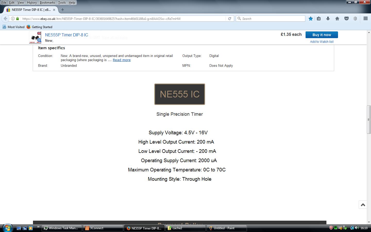
Thanks With regards the current, I'm just going on the specifications on the ebay page where I purchased it. I must admit it does seem rather low to me, but I don't want to burn the chip out (Being a total novice I just want be careful)

-
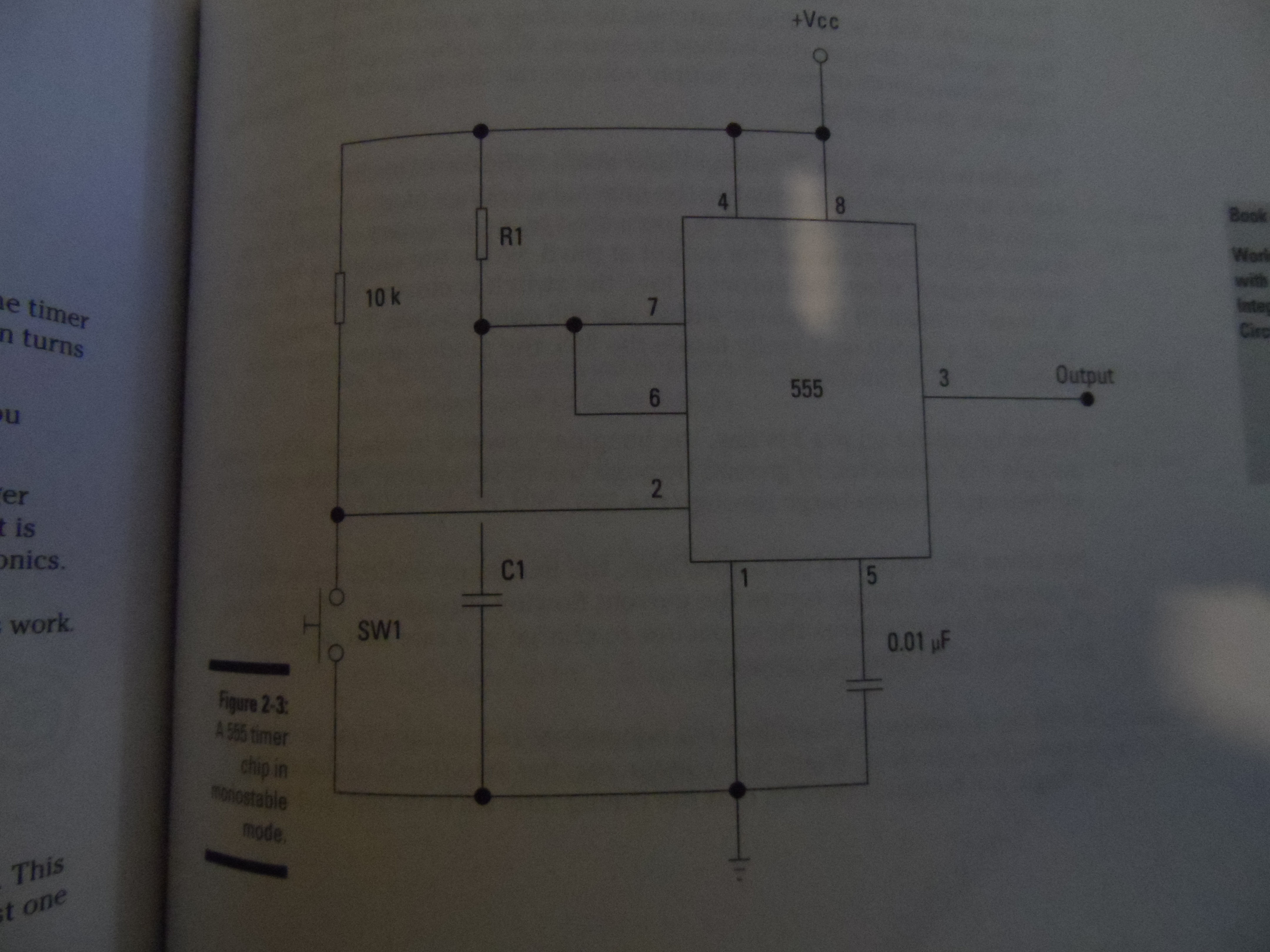
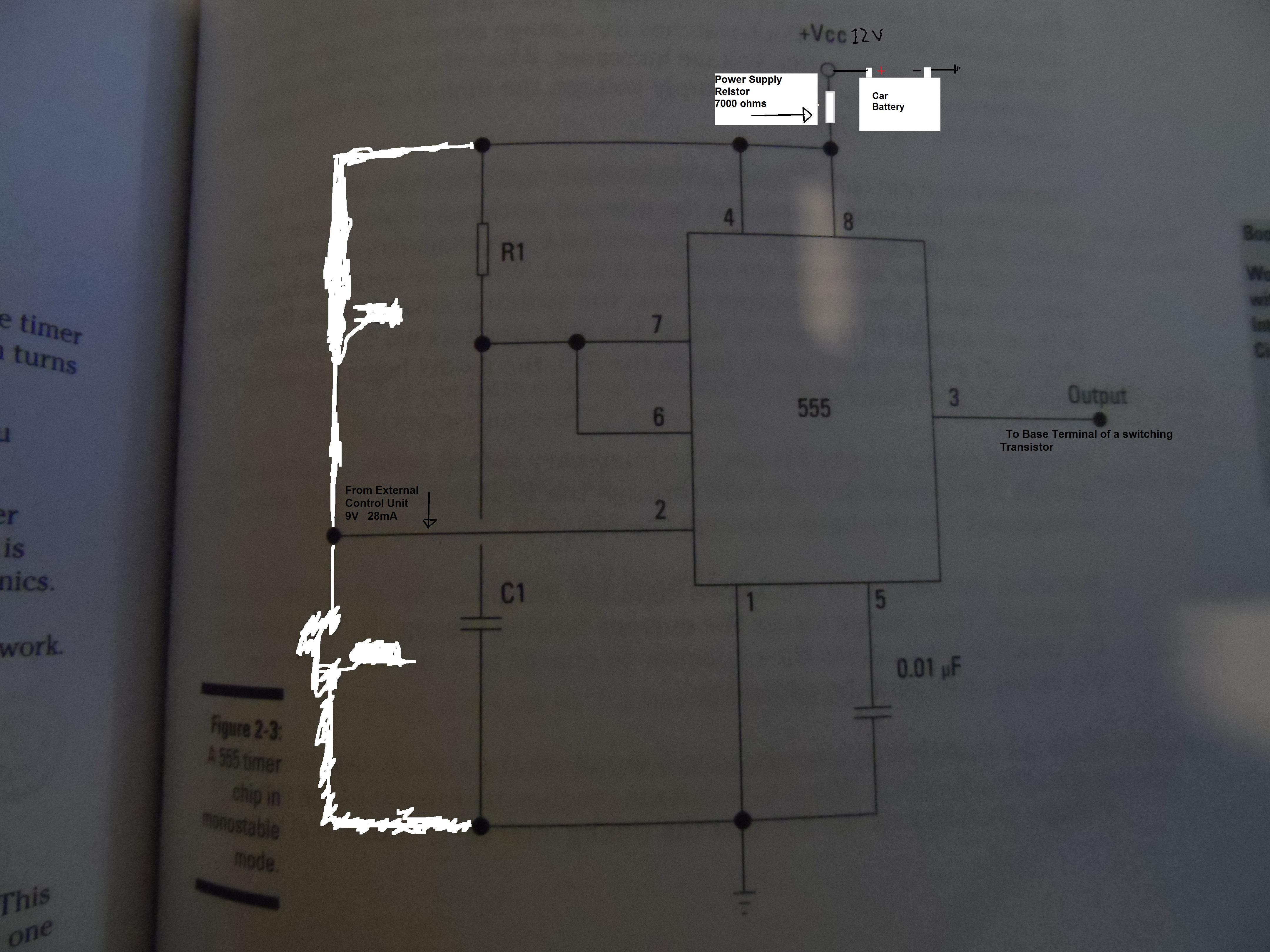
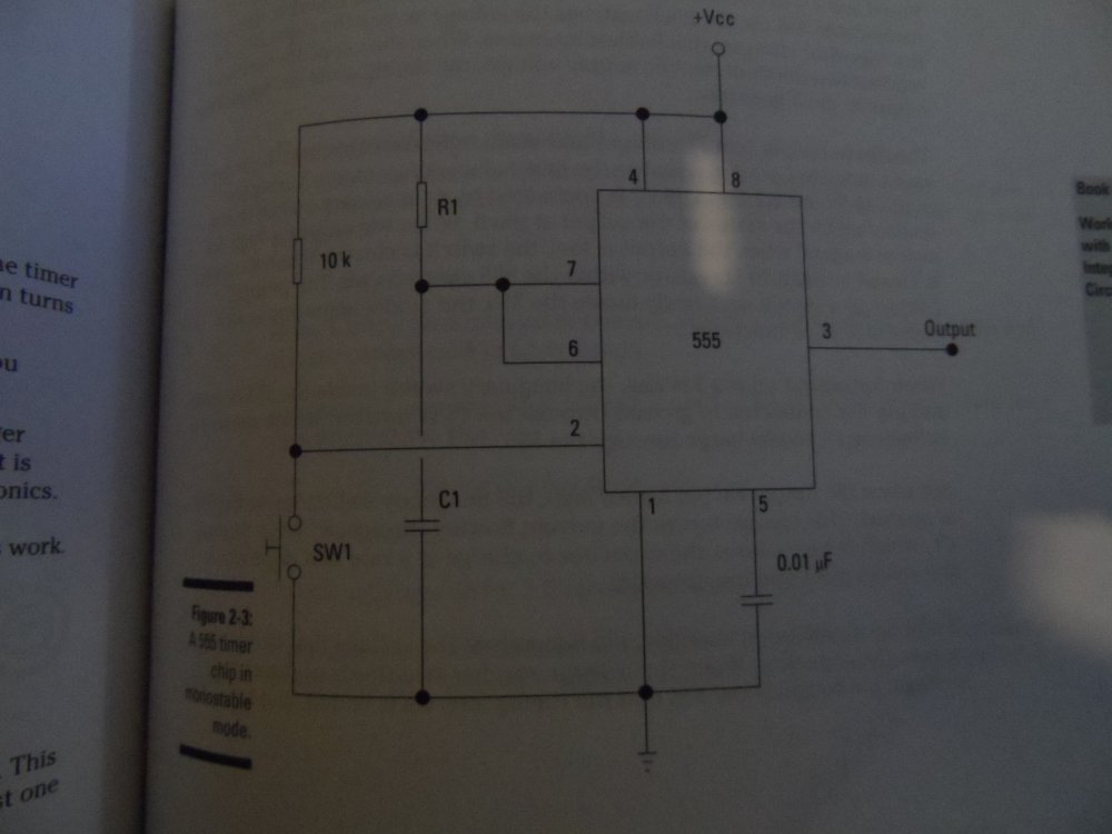
I am trying to use a 555 chip in monostable mode to control a pulse to operate a motor. I will be powering it from the standered car battery, so to get the current down to the required 2000uA, I will have to use a resistor around 7000ohms What I want know is does this resistor have to be added in to the resistor/capacitor caculation for the timeing interval. Or Can the resistor at R1 now be ommited First picture is the original diagram I used as a base for the circuit Then second picture with my modifications (caculations for R1 and C1 yet to be worked out)

-
What would be best to feather the edges of the old clear coat? Wet & Dry paper? If so what grade?
-
Does the rough edge need sanding or flating back to stop any more peeling?
-
Anyone have advice for a DIY fix for this issue? Not looking for anything show quality, just a smarten it up job. Full respray is not an option due to cost.