Jump to content

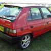
Coming soon, the greatest Favorit project ever! (Probably)


favguy

Recommended Posts

And now for your entertainment, I present to you, the correct way to make a coupler... :rofl:

So having aquired yet another clutch disc, I set about grinding off the rivets and removing the unnecessary friction disc, leaving a nice shiny torque damper, this time to be used the right way around and mounted in such a way as to transfer the torque from the outer edge in as it was designed. If this is where you expect a picture, er.. sorry, forgot to take one at this stage! So... moving swiftly on...

I now welded the hub to a suitable piece of 6mm plate steel, as both parts were over 5mm thick at the weld point, the juice could be turned right up and a nice neat heavy weld achieved. I then trotted off to the local machine shop to get it worked over on a lathe to the right diameter and have any runout removed so that it will run exactly true. following this a trip to the pillar drill for the mounting holes and here's the end result:

DSCF2111.jpg

DSCF2110.jpg

Much better already I think!

An alloy spacer ring was next made up from 5 inch round bar ordered cut accurately at 15mm and checked for complete flatness on a thick glass plate, turned out it was, completely flat that is! It was drilled out to suit and here it is finished:

DSCF2119.jpg

The torque damper had to be split apart in order to insert the new mounting bolts and to allow the mounting plate to be centred and clamped tight to the other components for accurate drilling, this involved grinding off the rivet heads, removing the original rivets and replacing them with high tensile bolts, threaded spacers and nuts. These were torqued up to the maximum recommended and then the bolt end "rivetted" over the nut to ensure they stay as tight as the original rivets:

DSCF2120.jpg

The next set of pictures shows the build up sequence to finished:

DSCF2122.jpg

DSCF2132.jpg

DSCF2127.jpg

I'm pretty happy with the end result and think it should now go the distance, only time will tell ;)

So whilst on a roll from the coupler being finished I moved on to the adapter plate..

Edited by favguy
Link to comment
Share on other sites

The adapter plate turned out to be very easy, the Favorit gearbox bell housing is nice and round, so easy to make a plate for. A 332mm x 332mm section of 25mm alloy plate was bought in.

For those of you interested the alloy used for the coupler and adapter plate is 6082T6 grade, I believe it's aeronautical grade, so good enough for the Favorit :rofl:

It was taken to the local machine shop to be cut to 330mm outside diameter and 140mm internal diameter, with a part radius cut in the side to clear the half shaft.

I then marked it up and drilled it for mounting to the motor:

DSCF2149.jpg

Once bolted tightly to the motor, we can move on to the final drilling for the transmission mounting, but..... :S

We can't just yet, as it seems I overlooked something else...

The motor was previously foot mounted and is now going to be used face mounted, it didn't occur to me when I drilled the face for mounting that the only part of the drive end housing that had actually been machined when the motor was made was the mating face to the steel yoke of the motor and the bearing housing, the face of the motor itself is as it came out of the casting mould and although that was fine in its previous life and it doesn't look to bad at a casual glance, it's not even close to the perfectly flat and true surface we need to mount it to the mounting plate and gearbox. So it's been removed from the motor and taken in to the machine shop to be worked over. I dropped it in this morning, once it gets back we can resume the fun.

So that's all for now folks, be back soon.

Paul

Edited by favguy
Link to comment
Share on other sites

You were right in ditching your first attempt!!! Looked so carp compared to the second attempt!!!....you can tell when something looks just right!!! B)

Link to comment
Share on other sites

Yup. Second attempt definitely looks like the better one!

Can't be far off getting some stuff bolted together now? How you intend on mounting the motor?

Phil

Link to comment
Share on other sites

Hopefully the motor, coupler, adapter plate and gearbox will all be mated together and tested this weekend :yes:

I'll update with piccies before Monday ;-)

Link to comment
Share on other sites

OK, I made some good progress over the weekend and another milestone completed, the adapter plate and coupler finished, installed & tested B)

Started with the motor end cap which came back from the machine shop looking very nice and more importantly, now flat, so started by re-installing this onto the motor:

DSCF2141.jpg

DSCF2143.jpg

Next the coupler was fitted to the motor:

DSCF2146.jpg

The adapter plate was then bolted to the motor and the gearbox placed on top, aligned, clamped & finally drilled. Here's a pic. of it finished:

DSCF2167.jpg

DSCF2168.jpg

The gearbox I've used for prototyping is sacrificial, so a large cutout was made in the top to observe correct alignment and true running of the coupling at speed, flats were ground around the bell housing to allow for clamping prior to drilling and the rear mount had to be hacked off to give access for some of the drilling! Sad for this gearbox, but I can now be confident the now finished motor and adapter will bolt directly to the cars gearbox with perfect alignment.

A couple of pictures of the completed assembly rigged up ready for testing:

DSCF2160.jpg

DSCF2156.jpg

And a close up showing the coupler in situ:

DSCF2153.jpg

I tested at 24v in 5th gear, running up to about 2500rpm, nice and smooth, no vibration at all, so should all be good.

Next job is to strip out the cars engine bay, transfer the original gearbox to the motor and get the resultant drivetrain installed into the car. be back soon... :yes:

Regards, Paul

Link to comment
Share on other sites

  • 1 month later...

Back again to what must be one of the slowest ever projects! I hope you havn't all lost interest by now :rofl:

I think I'm going to call this installment:

The (petrol) Favorit is dead, long live the (electric) Favorit. :giggle:

On account of I'm actually going to get rid of the petrol drivetrain at last and install the motor, yay!! probably the most significant part of the build really, so here we go...

I started by removing all of the now surplus petrol drive related parts, the pile you see below isn't even all of it, there was also a carbon canister and a huge plastic box thing thet was fitted to later favorits before the air intake:

DSCF2175.jpg

Surprisingly, the engine bay still looks quite full even with all that lot removed, below the drivetrain is ready for removal:

DSCF2182.jpg

The driveshafts were firstly removed and spare splined shaft ends inserted into the gearbox to keep the crown wheel in place and we're ready to go. Removing the drive train complete is remarkably easy and can be done by one man using the method shown. The trick is to get a sturdy table and place it underneath the car lift, the lift is then brought to about 6 inches above the sump, and wooden blocks are strategically placed under the engine and gearbox for support, carefully leaving an equal gap between all the blocks and contact surfaces. The lift is then slowly lowered until the blocks are in contact with the drivetrain, the final mounting bolts taken out and up goes the lift..

going...

DSCF2184.jpg

going...

DSCF2187.jpg

gone...! :o

DSCF2192.jpg

It was almost too easy in the end!

And here we have a nearly empty engine bay ready for cleaning and prepping for the new electric drivetrain:

DSCF2202.jpg

As we can't be bolting a dirty old gearbox to the now very clean and shiny motor and mounting plate, I wanted to clean this up before fitting. The problem with aluminium is it gets covered in powdery white oxide over time (due to our crappy damp climate!) and if you spend hours carefully cleaning and polishing this all off, within a month or three, that shiny gearbox looks terrible again.

So I decided after cleaning it to paint it to make it look like factory fresh aluminium, but with no corrosion nonsense. After a coat of acid etch primer, primer & two coats of metallic silver basecoat, here she is:

DSCF2209.jpg

DSCF2207.jpg

I didn't laquer it as this would make it look too shiny, the satin finish of the basecoat looks very much like factory fresh alloy B)

You'll also see in the last picture that I've fitted a blanking plate for the starter motor hole. This was made from 2mm stainless steel and given a nice brushed finish using coarse grade wet and dry.

OK, that's your lot for now, I'll be back very soon with mounting to the motor, engine bay prep. and drivetrain refitting. then we have to make the new drivers side motor mountings, having measured up, I know thats going to be, err... interesting :S ...

Paul

Edited by favguy
Link to comment
Share on other sites

Just a thought...

All of the surplus bits are now in the classifieds section if you need anything, please drop me a PM and we can talk.

Regards,

Paul

Link to comment
Share on other sites

Great news, your project is really reaching the most interesting 'crossover' point with the power testing you've done. I just re-read the thread to remind myslef of the hurdles you'd needed to overcome. A really great project.

Best wishes

Matt

Link to comment
Share on other sites

  • 2 weeks later...

Thanks for the compliments Matt, although far from finished, it will actually be electrically powered by the end of the next few updates, a big milestone :rofl:

So where had we got to...

OK, it's time to finally mount the transmission to the motor permanently, build and fit the drivers side upper and lower mounting hardware, engineer and fit the rev. counter solution and make and fit the temperature sender to the motor. What we will then have is a pre-assembled complete drivetrain ready to bolt back in to the engine bay (after first cleaning it and touching in any minor paintwork that needs attention whilst it's empty).

Starting with the mounting. This was a little more complicated than I had expected (although I didn't really know what to expect!) but turned out well after a little thought. The original mounting comprises an upper main mount on the end of the engine just below the head gasket joint. this also doubles as the water pump and this takes the main weight of the engine. At the bottom, below and to the rear of the right hand side of the engine is the lower mount this is at the end of a rod bolted to the subframe, the mount end bolts to a steel casting jutting out from and bolted to the rear of the engine and acts to control the twisting force of the engine when power is applied. So far so good, but when we replace the engine with a motor, the problem is there is just much less of it, so to speak! The top mount is above the top of the motor and the lower mount is well below and to the rear of it.

Anyway after much sitting and contemplating, measuring, drinking of tea, considering direction of forces and making sketches, I had a plan... The first job was to remove the upper mount/water pump from the engine. The water pump parts were then removed and the pipe stub and pulley mounting castings cut off flush with the main casting. It was now beginning to resemble something other than a water pump. just to remind you all, the picture below is what it starts out looking like, the altered version can be seen further down on the finished mount:

QCP3153.jpg

With the original mount altered as necessary, I moved on to make the new assembly needed to interface the mounts with the new motor. Firstly the gearbox was mounted to the motor and the drivetrain put back in the car with the gearbox mount re-attached and the motor supported by a temporary sling from a beam placed across the engine bay, after much fine tuning, everything was aligned where it needed to be and measurements were taken to allow fabrication of the new steelwork. (sorry no pics of this, got too carried away to stop and take any!)

This was firstly prototyped in plywood and chopped around until I was happy with the results. It then took a total of seven hours of cutting, heating & bending, grinding, drilling & welding to convert a 600mm x 150mm plate of 4mm steel into what you see below.

Picture below shows the assembly ready to paint after an hours soak in phosphoric acid. This removes the surface scale from black drawn steel along with any surface rust and leaves a phosphate coating to help prevent the dreaded rust:

DSCF2226.jpg

And after a coat of etch primer, more primer & gloss black top coat:

DSCF2231.jpg

I must admit to being pleased at this point, this is the last of the structural metalwork finished, yay!! It's pretty much all electrical and a little bracketry from here on in. :D

So the drivetrain was removed once again from the car and the modified (and now painted ;) ) upper mount bolted to the new mounting assembly, which in turn was mounted to the motor, now ready for it's final & permanent installation.

But a little more fettling prior to this, starting with the solution to the rev. counter signal.

The later Favorits have the rev counter signal provided from the ECU, this in turn gets it's signal from the speed sensor mounted at the top of the flywheel. It sits above the flywheel behind the ring gear. at this point on the flywheel there are two sections cut out at 180 degrees to each other that the sensor picks up as the flywheel rotates. As we are losing the flywheel, the sensor needs to have this signal duplicated from something else. The solution was to relocate the sensor to the tailshaft of the motor and to provide a scaled down version of the flywheel arrangement via a pulley with cutouts the same percentage of the circumference as on the flywheel.

Using the pulley that came with the motor, this was turned down to an appropriate size and had the two sections cut out to generate the signal:

Primed:

DSCF2214.jpg

Finished:

DSCF2221.jpg

A suitable bracket was made to mount the sensor:

DSCF2234.jpg

And everything assembled:

DSCF2238.jpg

And fitted to the drivetrain:

DSCF2247.jpg

As mentioned earlier, the signal for the rev counter is processed by the ECU, so I needed to keep it to do this. What I didn't need however was the huge ECU, loom and connections sat in the engine bay doing nothin else. So the loom was removed leaving just the speed sensor input along with positive and earth to the ECU and the rev counter signal wire. I wasn't sure if the ECU would still function and provide a signal with all the other sensor inputs now gone, but it does :)

But I still don't now need/want this thing in the engine bay:

ecufavorit.jpg

So, I stripped down the ECU to just the circuit board, soldered the necessary wires to it to run the rev counter only and mounted it into the smallest maplin component box that would fit:

DSCF2264.jpg

It's still too large for what it's doing, but it will now mount neatly under the dash behind the glove box out of site.

One more small job whilst the motor is out was to make a temperature sensor. this simply comprised drilling out a suitable length bolt and inserting the sensor that came with the dash guages fitted earlier using a little epoxy.

This was then screwed into the motor casing using one of the now defunct original mount holes. The other five holes were blanked off with stainless grub screws and a little threadlock whilst I was at it.

Sensor:

DSCF2267.jpgsensor pic

Installed:

DSCF2251.jpg

So, we've finally got a completed drivetrain ready for final installation:

DSCF2262.jpg

DSCF2257.jpg

Next up, final engine bay prep, then in she goes! :rofl:

Back soon.

Paul

Link to comment
Share on other sites

I suspect there's a more elegant way of getting a rev signal, but if it works it works and can't say I'd have managed to do as good a job as you have. Awaiting videos of running and 0-60 etc :D:thumbup:

Link to comment
Share on other sites

I kept thinking that whilst I was fitting it all up! :D I'm sure if I was more up to speed with electronics I could have built a circuit the size of half a matchbox to deal with the signal to do away with the original ECU board, but there's so much more to do on the project, I just can't be bothered to re-invent the wheel on this when it's going to be hidden out of site anyway. As for the sensor itself, I'm not aware of anything else that could generate a suitable signal, it's not like there's a coil pulse to take off No1 cylinder anymore! :rofl: Anyway, this type or sensor is still used on nearly all cars today for crank position/RPM sensing, so it's good enough for this job! (although it does seem a "large" solution for what it's doing I must admit!:D

Right, onto todays progress...

I'm currently like a cat that got the cream I've finally got over the biggest hurdle of the build to date, the electric drivetrain is now back in the car, it's really just all electrical work now and a little bit of bracket making!

First I spent a good three hours cleaning the engine bay and removing and painting some minor rust whilst it was easy to access with everything out, then moved on to put the drivetrain in, an absolute dream to install, just set it up on the table, lowered the car toward it, fine tuned the table, and lowered the car very gently onto the mounts. Then I slipped in the bolts and took the car back up on the lift complete with drivetrain.

Just needed to shake the drivetrain to settle it on the mounts, then finally tighten all the bolts and re-install the drive shafts. A few pictures of the finished result are below. I can't believe how small the motor looks compared to all that petrol crap that came out!

DSCF2294.jpg

DSCF2301.jpg

DSCF2277.jpg

DSCF2280.jpg

DSCF2284.jpg

That's it for today, tomorrow I'm re-filling the gearbox with fresh oil and test running it on 12v or 24v in first gear. going to use the starter solenoid as a contactor and run a temporary on off switch into the car and have a tootle round the yard with it.

Regards to all, Paul

Link to comment
Share on other sites

Impressive. I guess you have something worked out for the brake vacuum, like a pump used on a diesel engine? Is airflow needed over the motor for cooling?

Link to comment
Share on other sites

Hi,

Yes, a vacuum pump and reservoir to connect to the servo, this will also double up for the cruise control as I need vacuum for this to run.

The motor self cools via its internal fan, I may or may not force cool it also, depends on how hot it runs. If I do, a cover band and gasket is fitted over the brush gear slots with a duct inlet in it, this in turn is piped to a high cfm blower fan, that forces air through the casing and out the fan end. come to think of it, I might fit a cover band ducted to an air filter anyway even if I don't use a blower, as it will keep the brush gear clean and free of any detritus. :D

Regards

Paul

Link to comment
Share on other sites

:o :o :o

This just keeps getting sooooooo impressive!!!!

P.S. is there any engine/gearbox mount to the lower rear to stop it rocking back and forward on the other two mounts????

Link to comment
Share on other sites

oops...

Put the same pic in twice, meant to add an underside pic, I've now swapped it out, you can see the lower rear mount in the pic. ;)

:giggle:

Ahhhhh...there it is!........Had me worried for a mo!...though you had missed sorting it out :giggle:

Link to comment
Share on other sites

I now have a major milestone to report... It lives, muwaahhhaa... :rofl:

Yes, the car is now officially electrically powered!!

Today I drove it using the motor. I connected up a 60Ah 12v car battery to the motor via the old starter motor soleniod, with a lead from the soleniod run into the cabin to a rocker switch to turn it on and off.

After first switching it on and off in neutral to be sure it was running smoothly through the gearbox, I got into the car, and switch in hand got ready to go...talk about anticipation! :o

I really didn't actually expect much to happen, thought I would need to add another battery in series before it did much more than rock the car, but thought I'd try it anyway. Well!!... I couldn't believe it, put it in first and flicked the switch and... it pulled off and accelerated to about 5mph!!! Woohoo!!! I drove it around my parents house and back on to the lift by which time it was getting sluggish (poor car battery!!) I measured up the distance travelled, a total of approx. 260 metres, (or 283 yards if you prefer).

I haven't been able to stop grinning since .

I checked it out under the bonnet after the inaugural run and all was stone cold except the starter motor solenoid which hadn't appreciated bieng on for about 3 minutes, so it was hot.

If it can pull like that from a 12v car battery, I can't wait to see what it's like on 144v, I'm pretty sure i'll never need to use first gear!!

I'm just sooo happy today :D :D :D

Regards,

Paul

Link to comment
Share on other sites

Did a little bit more testing today just to amuse myself, rigged up 2 12v car batteries in series to give 24v, took it for a spin, setting off in 1st even spun the wheels slightly as I've only got full on or off at present, so changed to setting off in 2nd, much smoother, got to just over 10mph! Did a total of about 600 metres around the house a few times, tested shifting between second and third up and down, worked great clutch free :rofl:

I Had to stop after this as the second battery is only 40Ah and on it's last legs anyway, so was not at all happy by then!

Also did a no load running test in neutral, 24v took the motor up to 2000rpm, nice and smooth, no vibration, so thats good. Anyway couple of pictures of the temporary rig up below:

DSC04578.jpg

DSC04579.jpg

OK, that's it for playing, got to get back to building now :D

  • Like 1
Link to comment
Share on other sites

Create an account or sign in to comment

You need to be a member in order to leave a comment

Create an account

Sign up for a new account in our community. It's easy!

Register a new account

Sign in

Already have an account? Sign in here.

Sign In Now
  • Recently Browsing   0 members

    • No registered users viewing this page.
  • Community Partner

×
×
  • Create New...

Important Information

Welcome to BRISKODA. Please note the following important links Terms of Use. We have a comprehensive Privacy Policy. We have placed cookies on your device to help make this website better. You can adjust your cookie settings, otherwise we'll assume you're okay to continue.