Papez
Members
-
Joined
-
Last visited
Everything posted by Papez
-
It should be around 1,1-1,2Mpa on a new engine, I found around 0.9Mpa for a worn engine, difference bellow 0.1MPa. 3bar (0.3MPa) is way too low. Rule out measurement error, otherwise it's really bad.
-
That could be the issue. Since it's a pushrod engine, any head-off procedure requires adjustment. Atleast twice, because the head gasket will squish a bit after a few heating cycles. It's possible that the clearance was set too low and valves didn't close properly. That can result in heat damage. Compression test would tell for sure. Tool for that isn't expensive.
-
Each video sounds like the starter has no load at all - which would suggest low or no compression. Did you set up valve clearance correctly after head gasket job?
-
What's the exact type? The 3-electrode plugs are what should be there, but the electrode spacing may be different. They won't spark like this. The plugs need to be connected to ground, normally it's done through the engine block. The first video was without plugs? It sounds like there's no compression, have you measured it? Diagnostics would say more. Basically the engine should run as long as you have fuel, spark and working crankshaft sensor.
-
This thread has been a bit co fusing, which method have you used in the end?
-
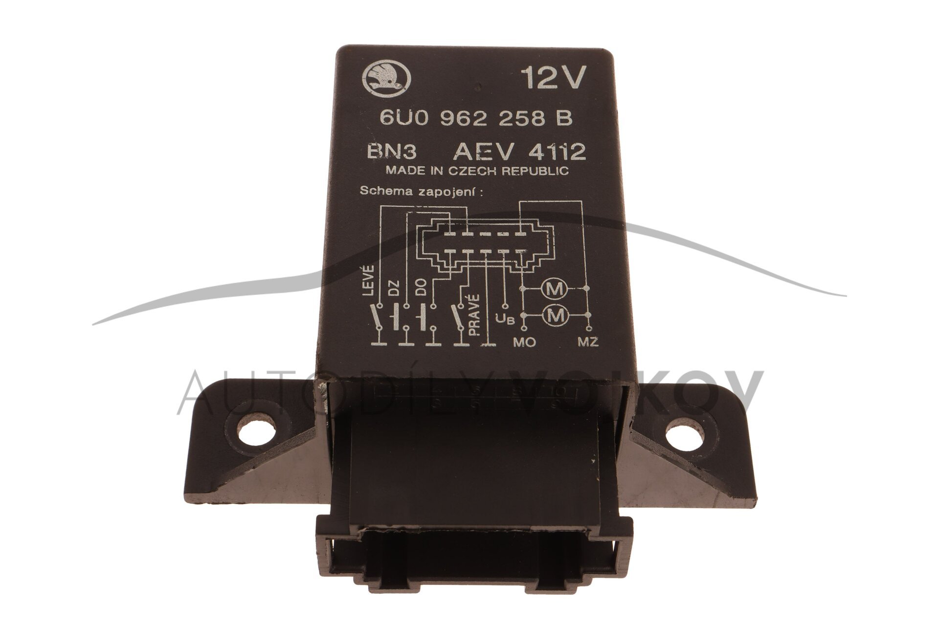
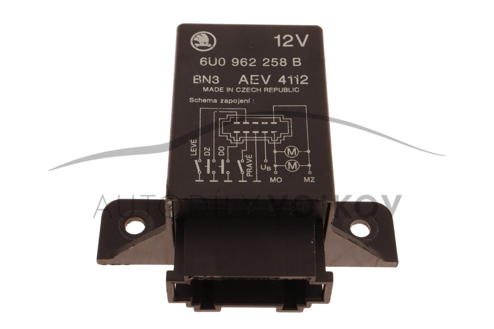
This information has been already posted on page 2. Your unit is 10-pin, it's same for B and C variants. As long as the switch has separate pins for backlight only - Felicia window switches can be used, for example. But other switches meant to directly control window motors have usually combined light and input power pins. There are also switches for lock/unlock, but I didn't find any Info regarding internal connections.
-
But you neither have a 1995- model or -A variant What's the question here? You are supposed to disconnect it from the gearbox before any work with the instrument panel, to prevent any damage. However, it's quite thick Bowden tube, it shouldn't break easily. What I did was, that I released the instrument panel clips once I had enough space to reach them, that made the whole operation easier. I didn't even need to remove steering wheel.
-
I didn't find anything suggesting that there is any difference. The wiring diagram appears to be identical
-
sch-koda is actually correct pronunciation, thought he sounds more like sch-koouda, it's pretty close. Favourite is not entirely wrong, since Favorit is Czech variation of that word.
-
What do you mean by "touch"? What did he touch it with? I though that I explained it clearly - yellow pulled to the ground - lock. Yellow disconnected from the ground - unlock. It's a position sensor input for the lock, not lock/unlock button input. Fact that it worked in the manner you describe at all is probably some debounce mechanism, which ignores disconnection that comes in short interval after the initial contact.
-
Yes. It disconnects switch in the motor from the ground, which will generate "unlock" state. This newer unit uses only "pulled to the ground" as a lock signal, open circuit as unlock.
-
1) you should've told him that the dashboard doesn't need to be removed. Only the panel around the instruments. 2) When talking about compromise, why don't you remove the panel yourself? It's a 10 minute job and you are apparently comfortable to work around the interior. Or do you want to hear this every time when a lightbulb in the instrument panel fails and pay for extra work to someone who doesn't know what are they doing?
-
To the ground, as shown on the diagram. Doors are also pulled to the ground, both on this and in car's wiring diagram.
-
I'd say "follow the diagram on he locker unit DZ for lock, DO for unlock"
-
I don't see how going around various electricians, trying to figure out working connection and messing with wiring is less work and cheaper, than simply putting two extra pins into connector that's meant for that purpose. The factory remote is connected like that. Why do you think there's no guarantee it will work? It's more likely to work than the other solution.
-
Quick sketch from my phone. You need to check that the switch really is connected like this internally. The left side is unlock - you'll need to split the yellow cable that connects the original switch to ground. Pressing it will disconnect the switch from the ground. Right side is locks - you need to tap into yellow wire without cutting it. Pressing it will bridge the original switch. There's still risk that this will not work and you'll end up with messed up door wiring. I'm not taking any responsibility for that, you've been warned and still deliberately ignores advice for the proper installation. But I want to help and it's your decision.
.jpg.319e2144f70018c5c219f73baced66a3.jpg)
-
This is connection for electric window. Output switches polarity, that's not what you need. You need to do a different connection, which will disconnect the lock switch from ground for unlock, and bridge it for lock.
-
Or you could just do it the correct way. Sooner or later, you'll have to remove the instrument panel anyway when some part of instruments or one of the switches inevitably fails.
-
Because it has dedicated pins for that purpose? You cannot just connect a switch in parallel. You need one switch in parallel for lock, and one in series for unlock, because switch in the lock motor works connected to ground - locked, disconnected from ground - unlocked. The older 6-pin unit you posted earlier worked the way you'd need, precisely because it didn't have this capability. Btw, what kind of electrician "who knows Fabias and Octavias" cannot read the VW-standard wiring diagram?
-
Either that (check drain holes in the heater inlet in the engine bay) or around the rotted window frame. Sealing it up, as d.fylaktos advices, is only a temporary solution. Anyway, water in the fusebox very likely drained the battery and it's possible that some corrosion happened. Make sure it's all dry and clean before recharging the battery, corrosion can damage the fusebox.
-
You mean window switches? They are 5 pin, but different connection than standard window switches. You can get same design with standard connection (and red backlight) - they were used in Audi 80/A4
-
But you have power steering, right? Cars with PS had 90A alternator and 6PK belt. Car without PS had only 7A alternator. It's possible that the compressor will fit into factory bracket... Who knows, maybe Alex even modified the kit to use the factory bracket with spring-loaded tensioner.
-
I said it before - these AC conversions are mess 😃 The manual at one point also shows alternator on top. In stock configuration, AC compressor is beneath the alternator, in place of the servo pump. That however requires different coolant pipe and hose to get around it, so that's probably reason why Alex had to do a slightly different accessory holder, which mounts alternator and compressor quite high. Another reason to implement two speed fan. Especially when we are required to run with lights 24/7. Problem with 90A alternator is, that it fits only into PS/AC bracket - PS variants were equipped with it from factory. Not sure if Alex holder could work with 90A alternatir
-
Felicia didn't have remote central lock integrated in the key, it was an extra fob: Quite often, the rubber band fell apart and fob got lost... But it's possible that you don't have remote lock system at all - it was available only with alarm system, you can check front A-pillars if there are ultrasound sensors and alarm unit in the engine bay, near the firewall (unit on the picture is pre-facelift, later models were different, but similar placement) Front pins should move freely, rears were always a bit more sticky. Most issues with the lock are caused by motors, but hard movement may be caused by lock itself. Hard to say until you remove the panel and check yourself. You can remove the motor and keep it connected to check if it moves freely by itself.
-
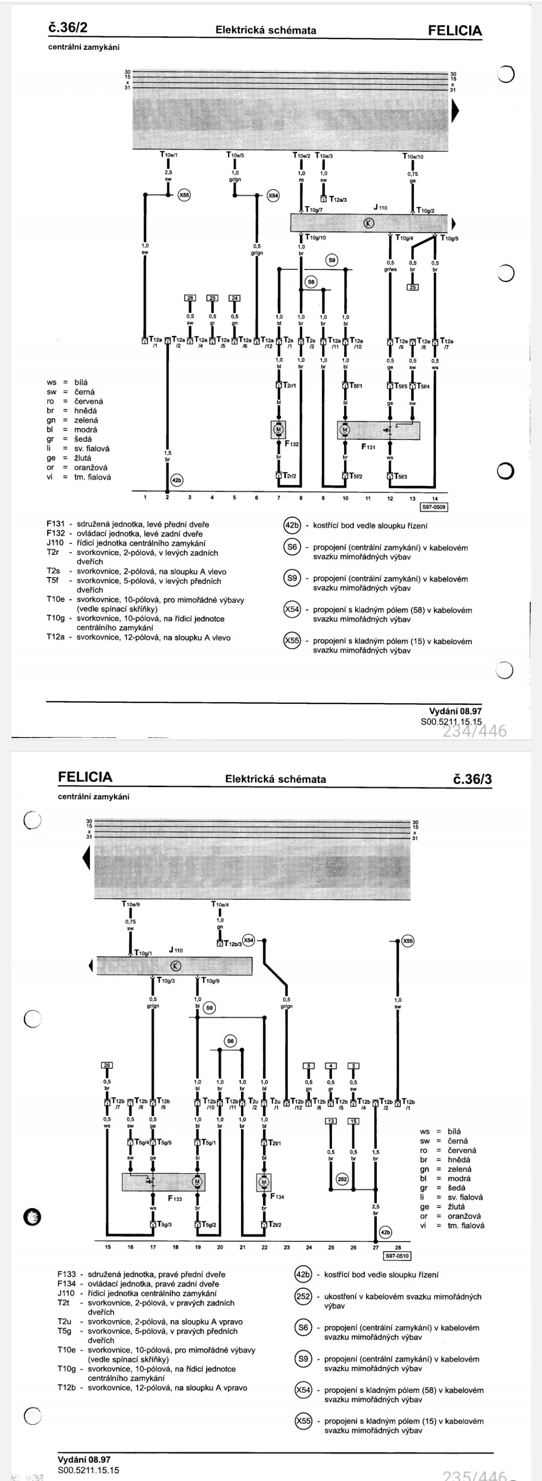
This is wrong wiring diagram, it shows pre-1997 with a 6pin unit. Plus, it doesn't show door connectors. This is the correct one: T12a and T2r are connectors under the carpet on the fron left A-pillar, T12b and T2u same on the right