ApertureS
Resident Member
-
Joined
-
Last visited
Everything posted by ApertureS
-
Skip the faf of all the online stuff, download, stick in on a usb and away you go
-
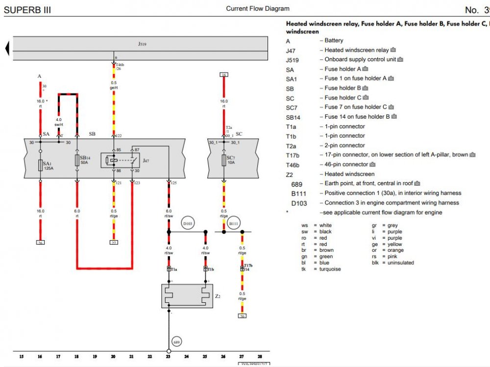
wiring diagram here.
-
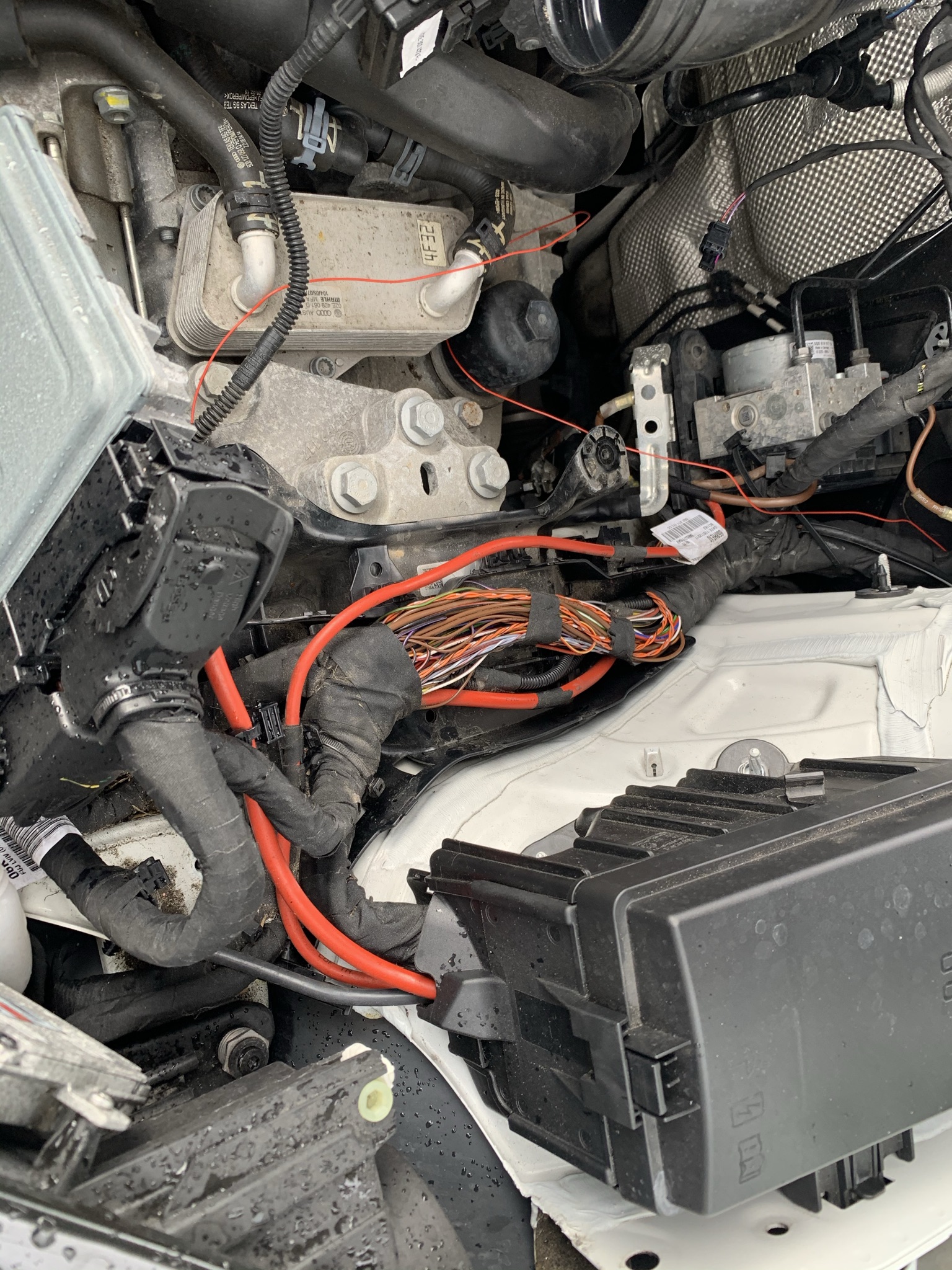
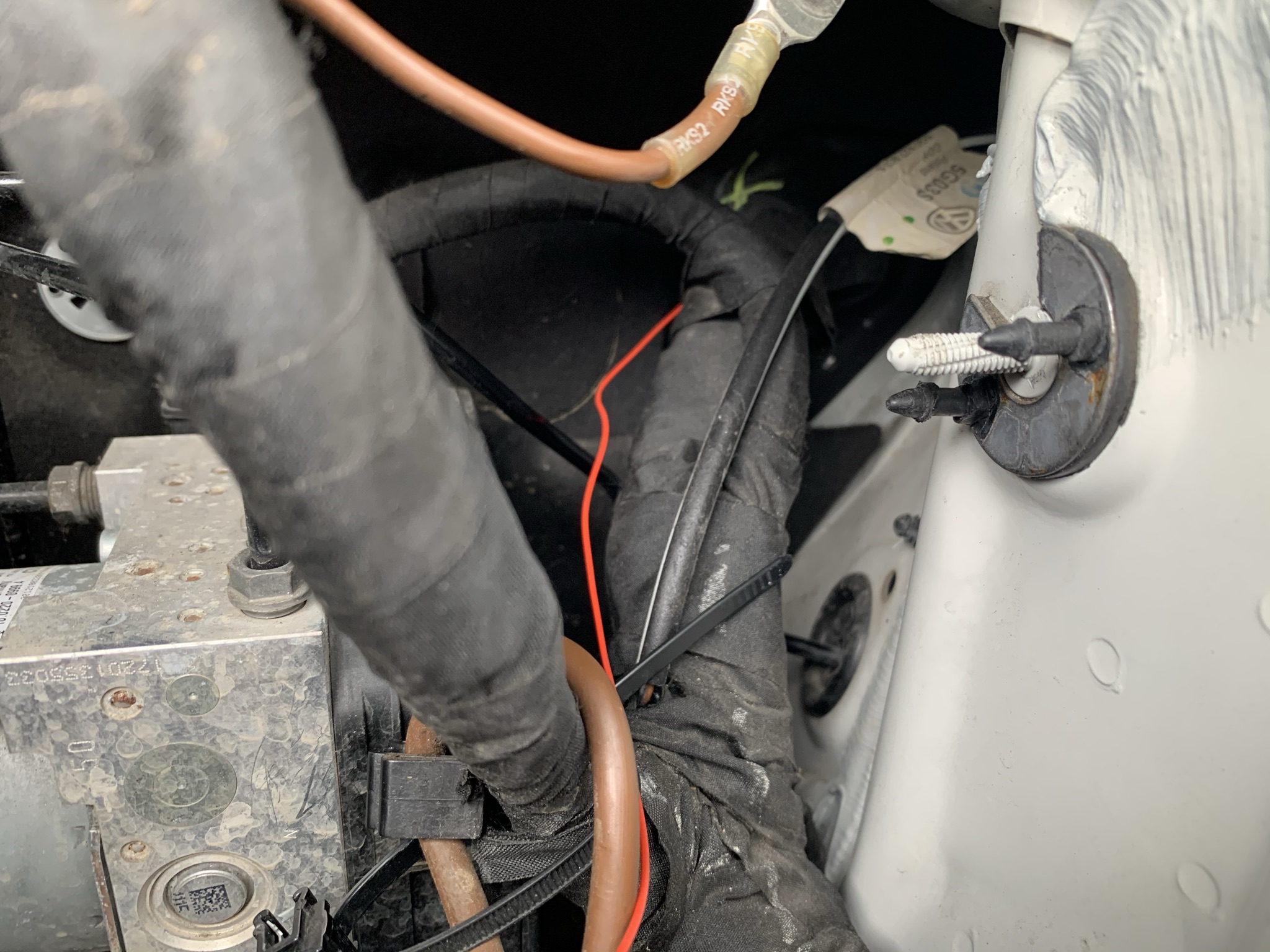
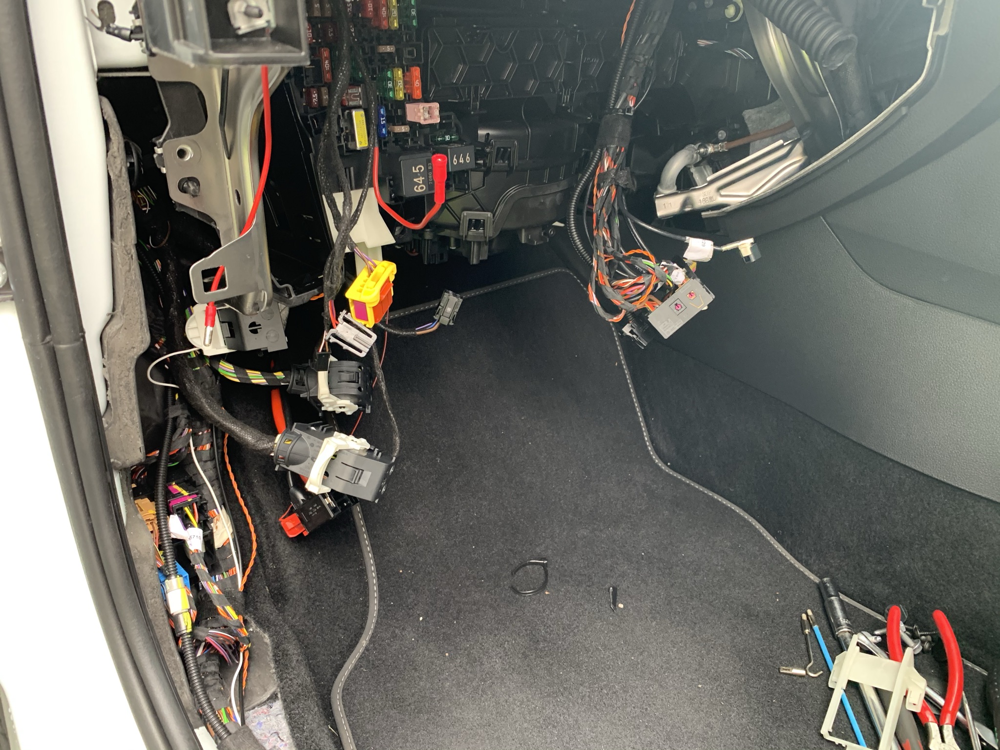
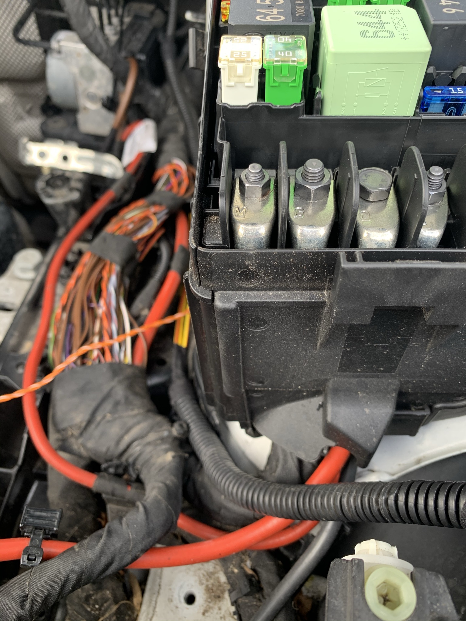
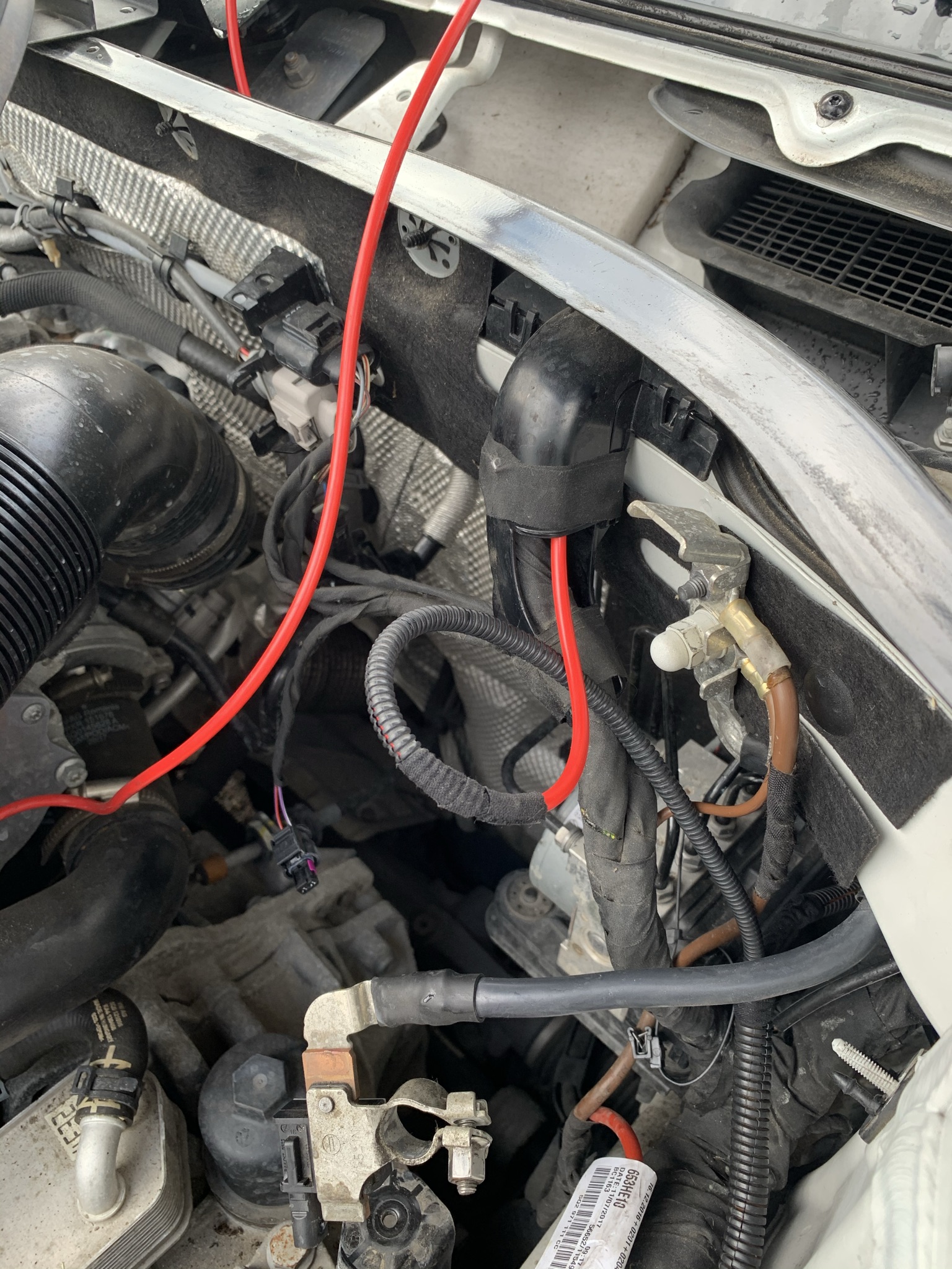
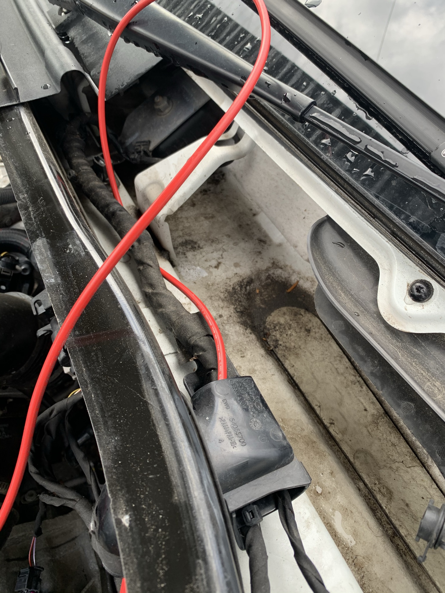
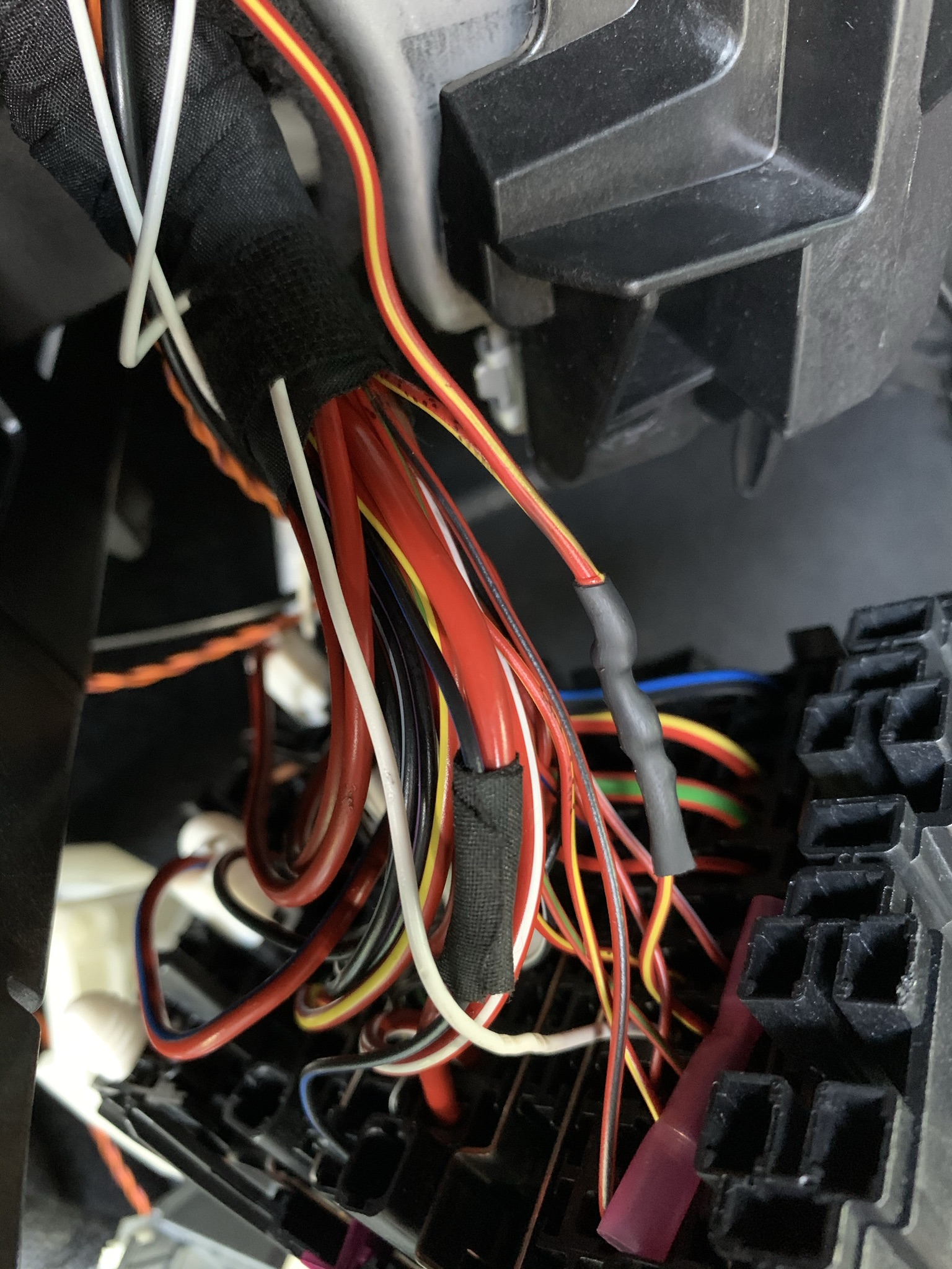
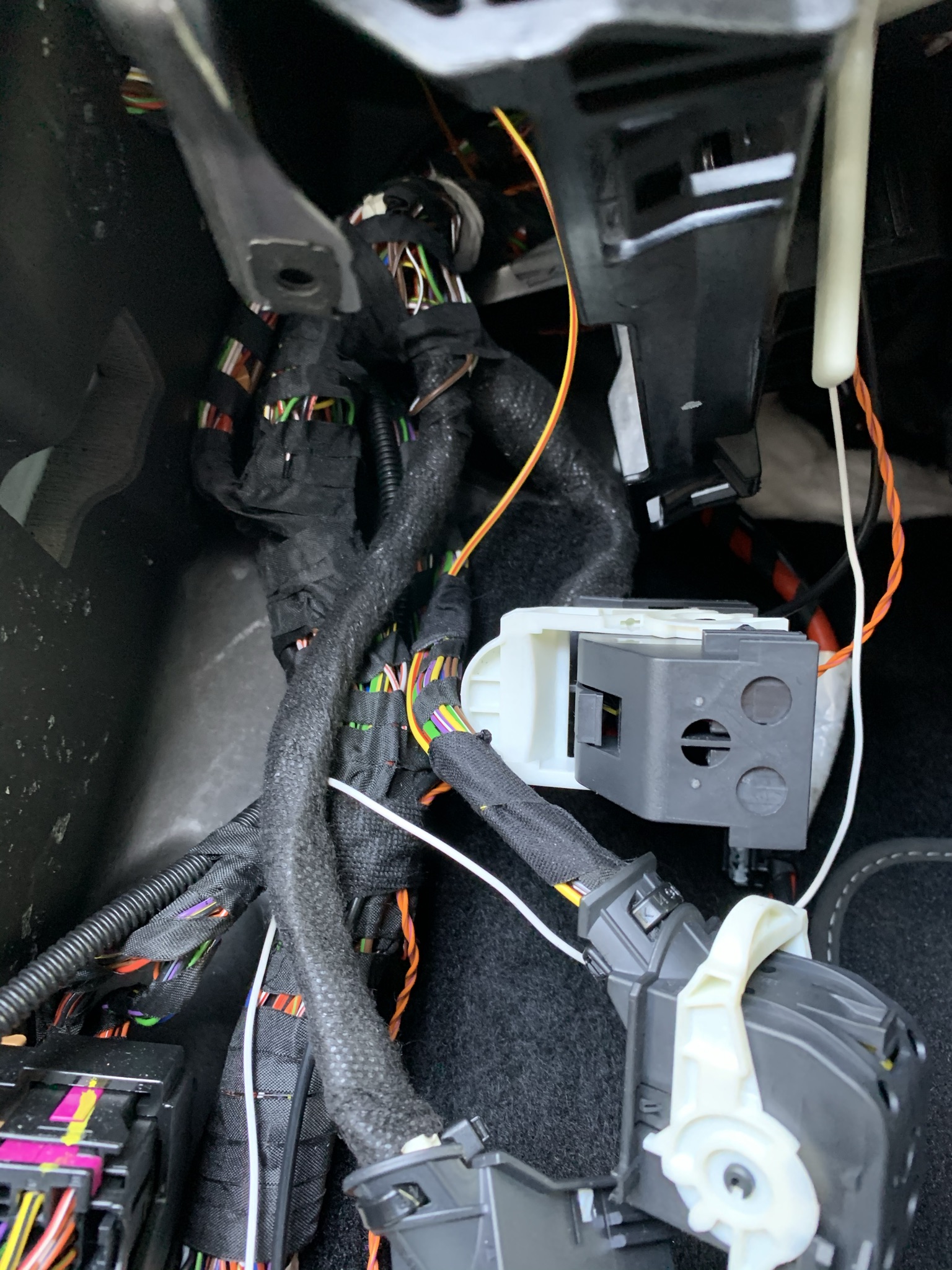
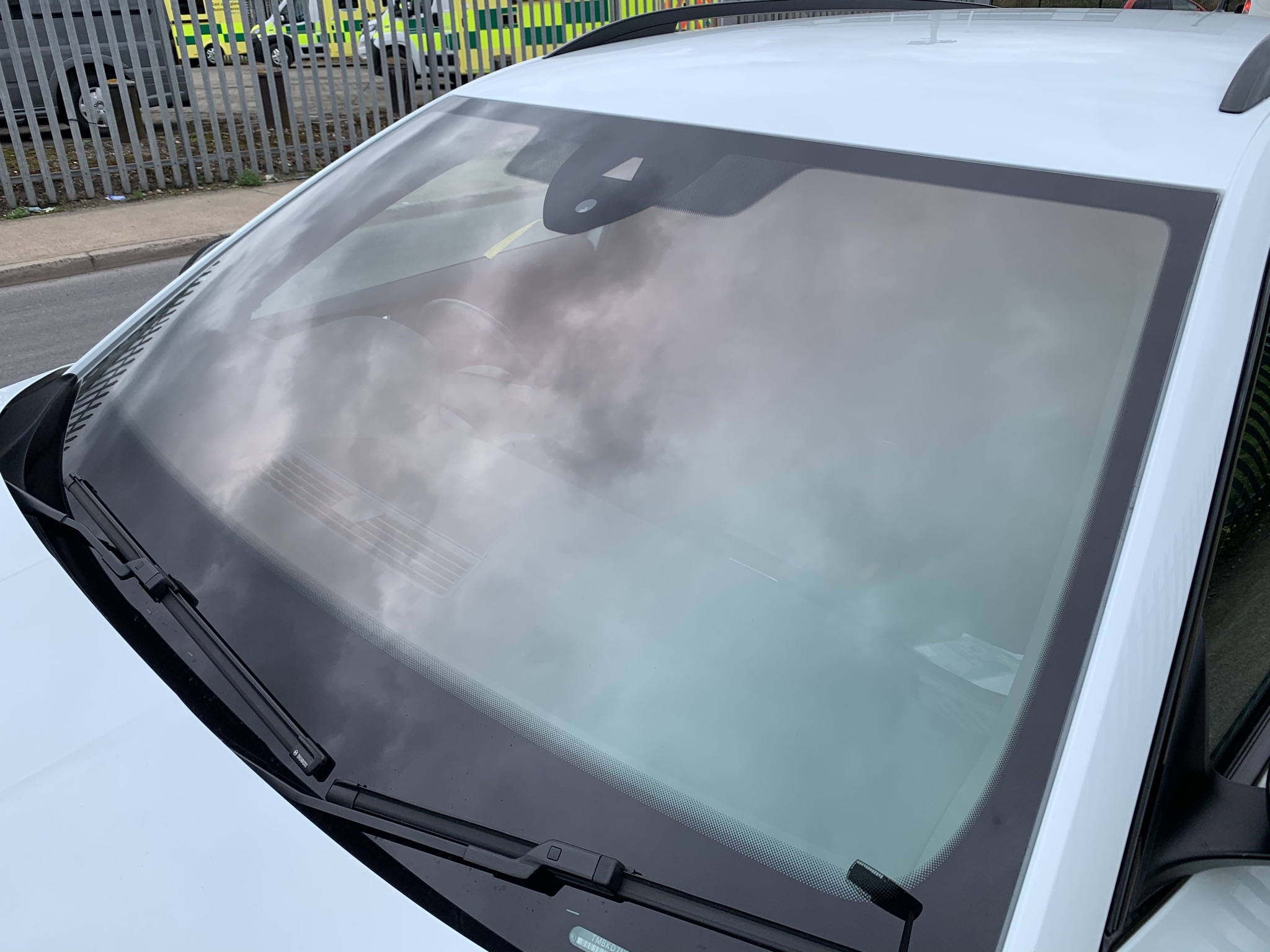
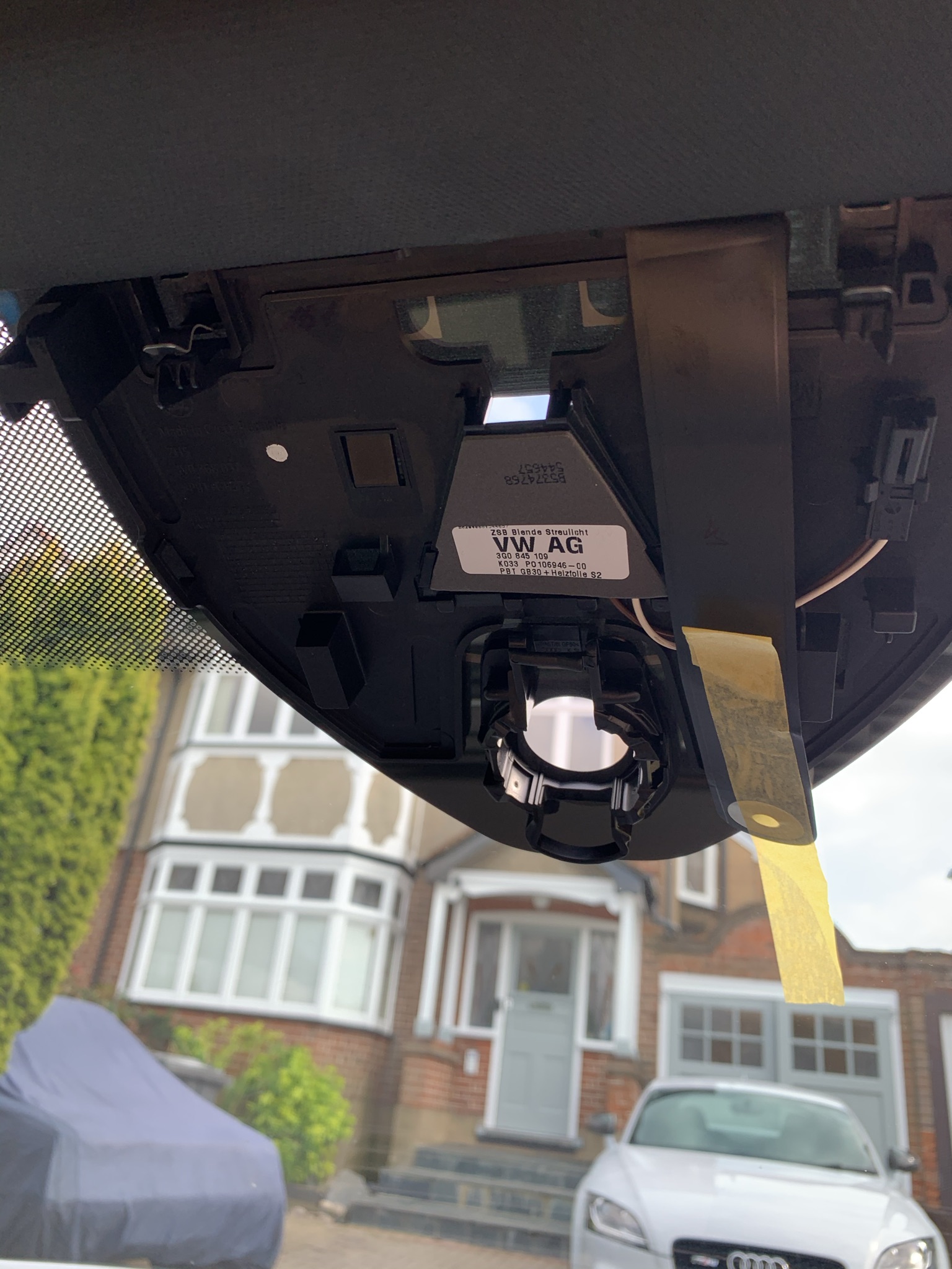
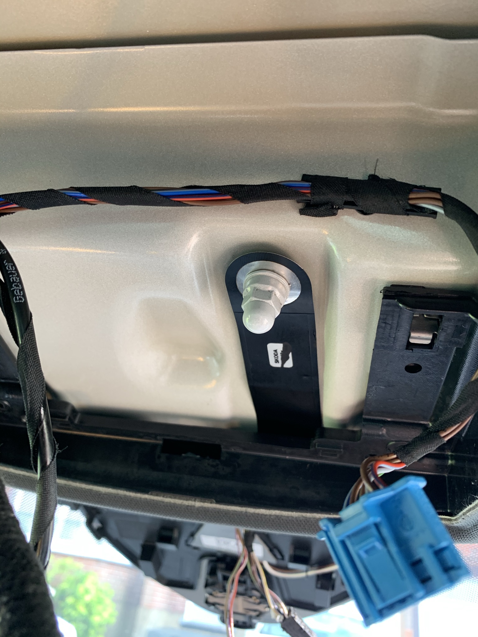
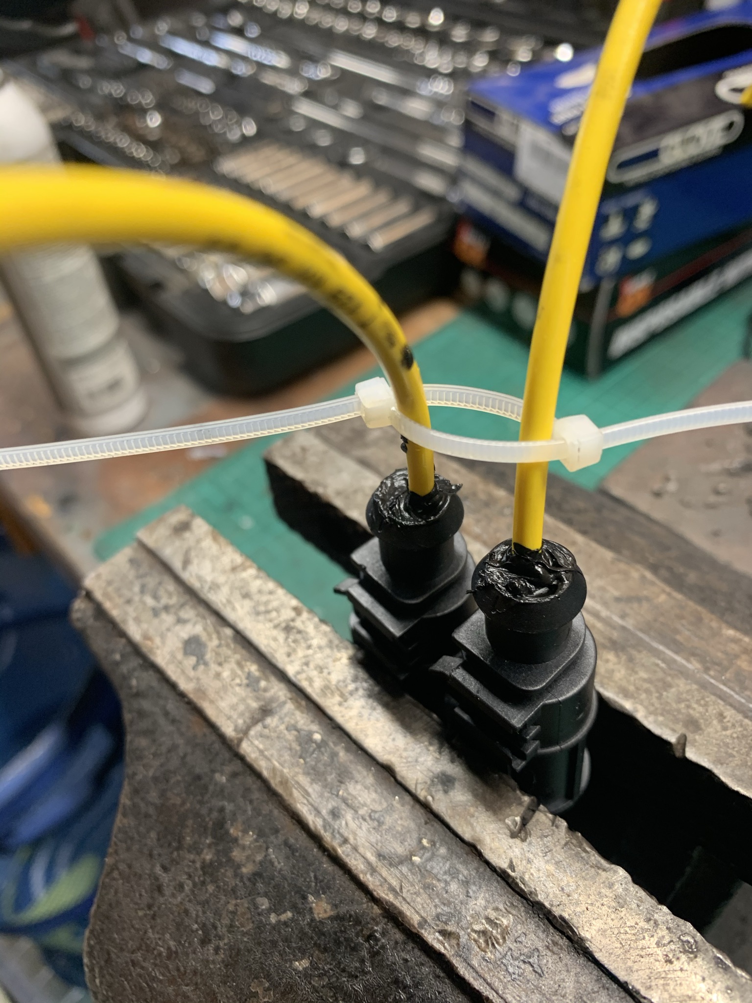
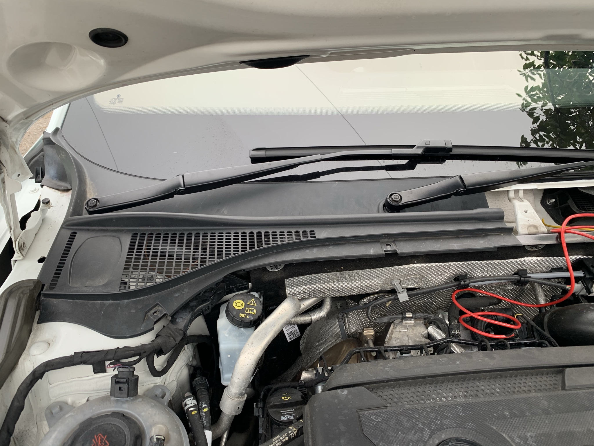
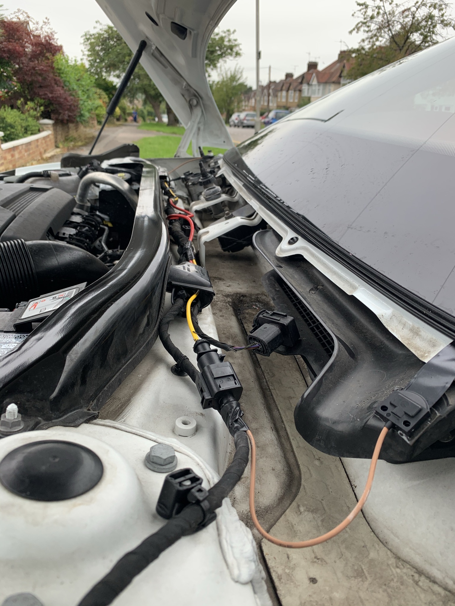
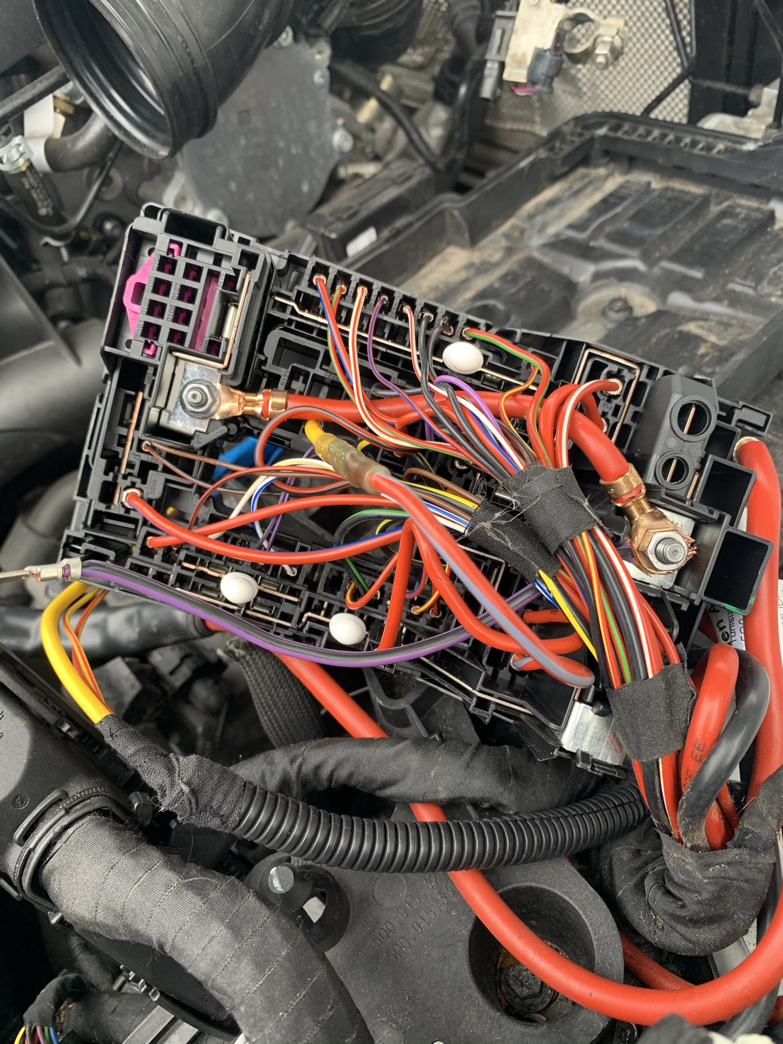
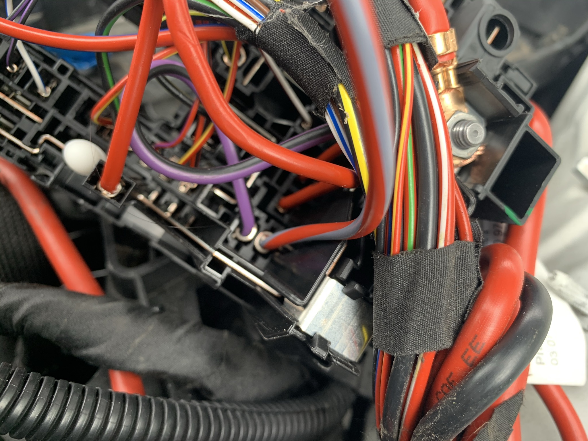
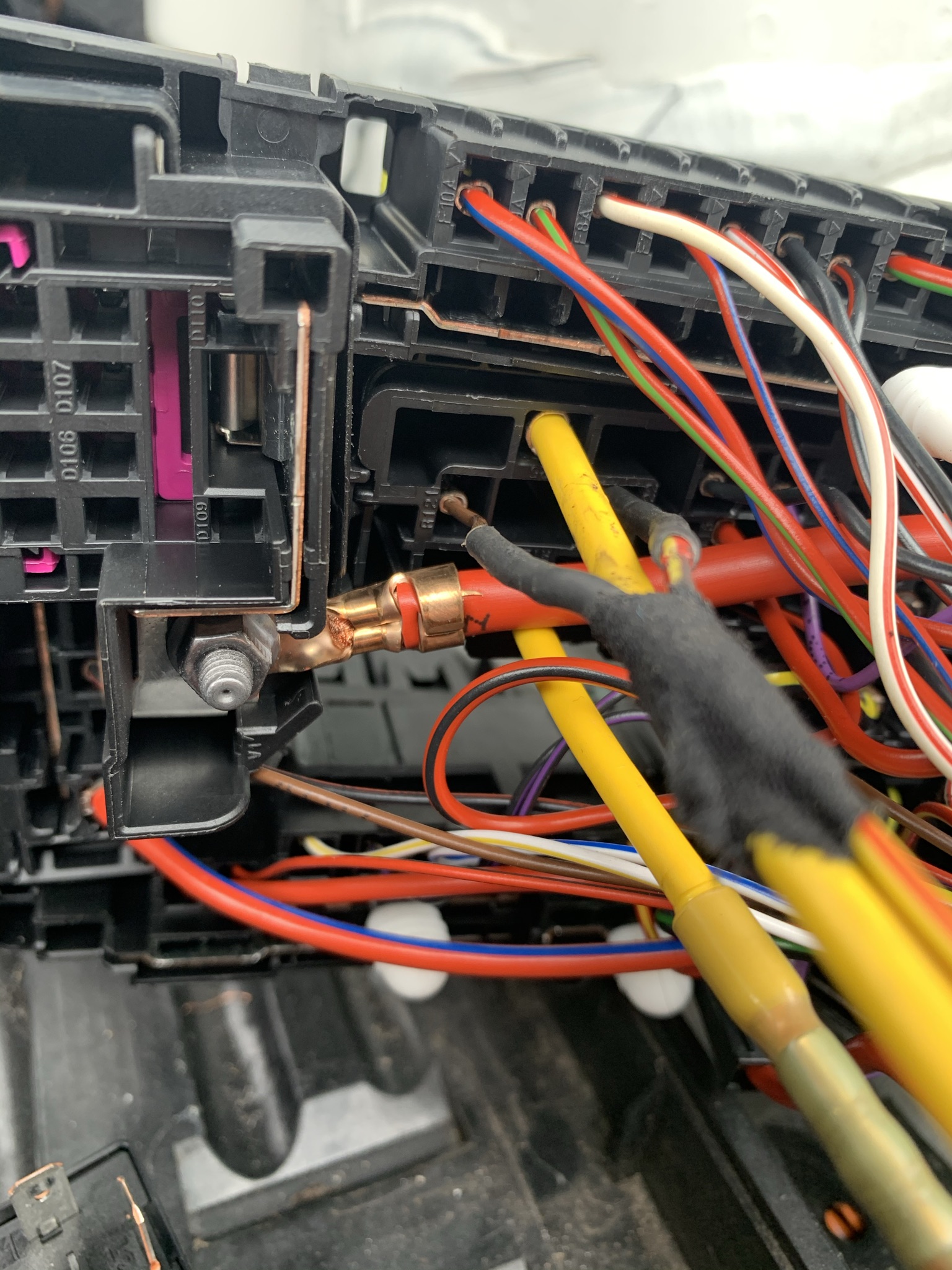
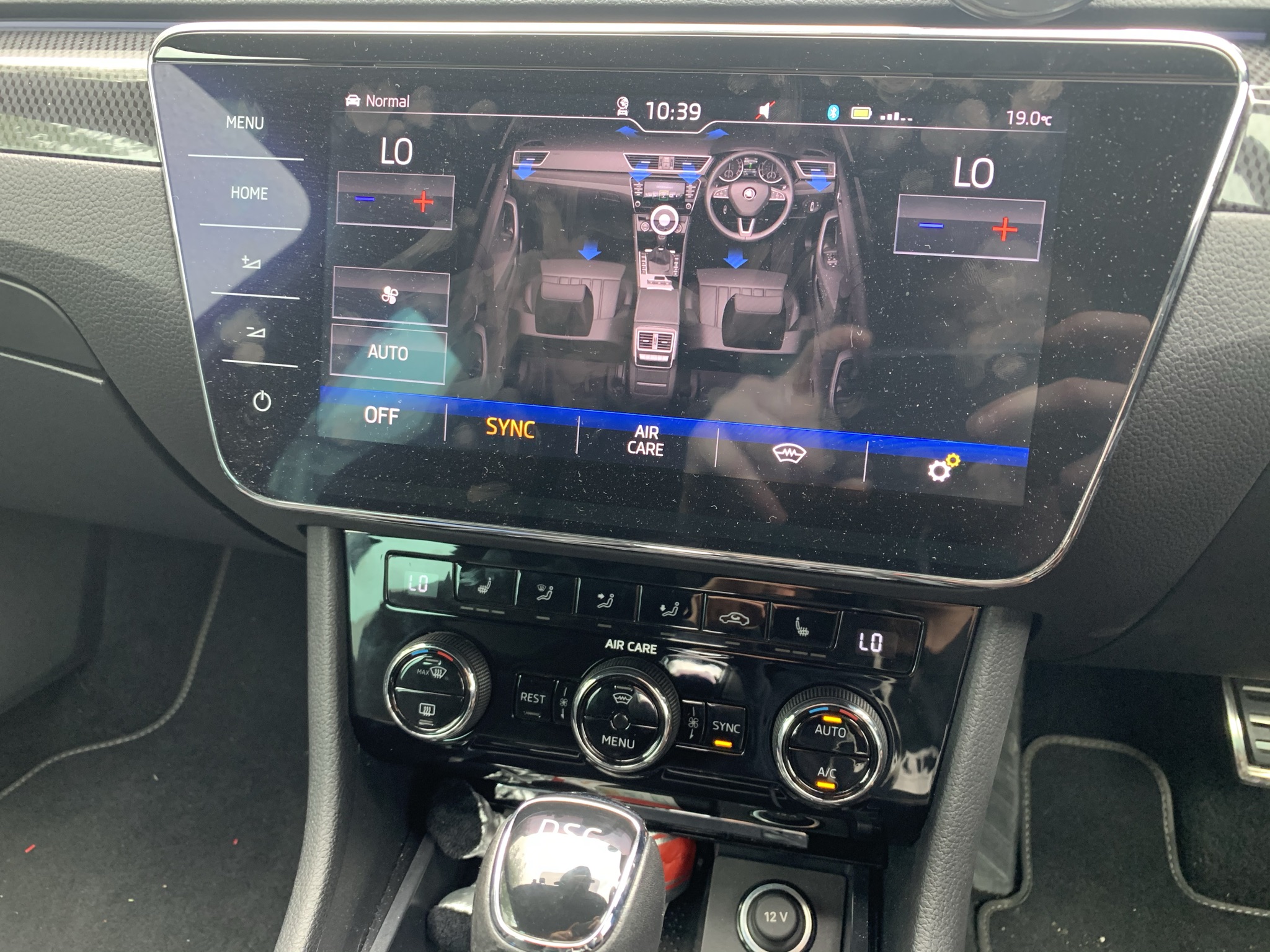
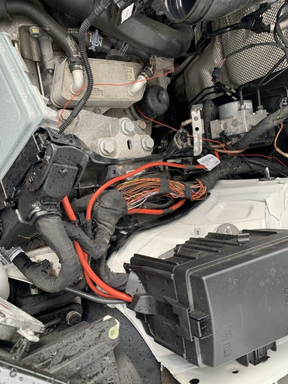
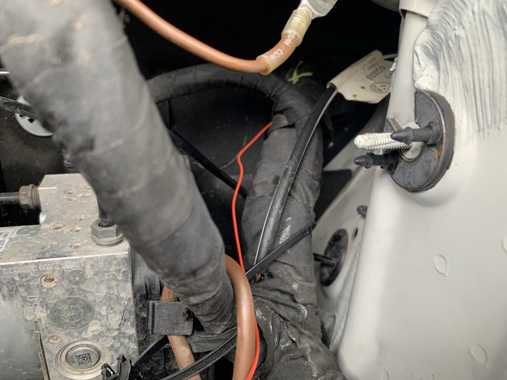
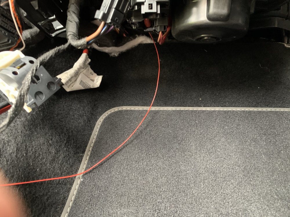
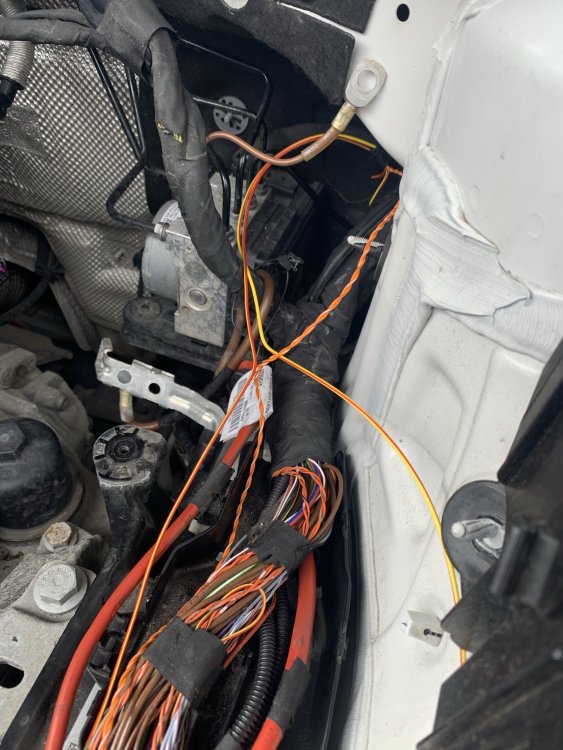
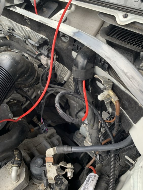
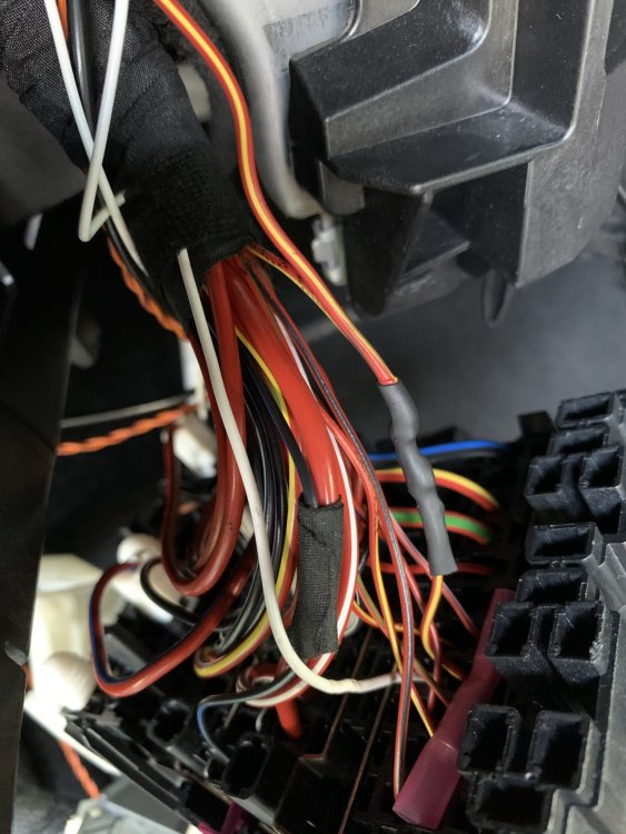
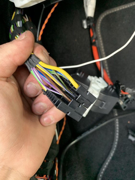
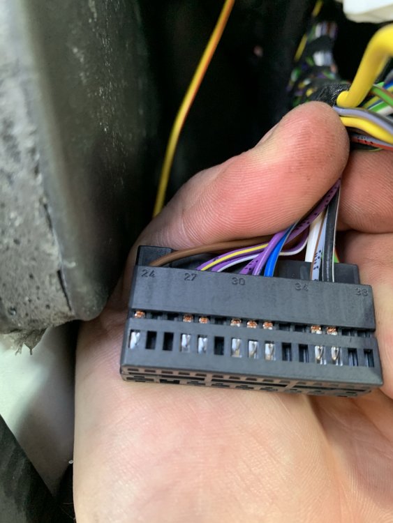
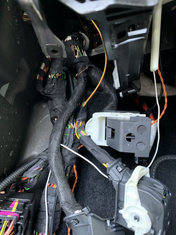
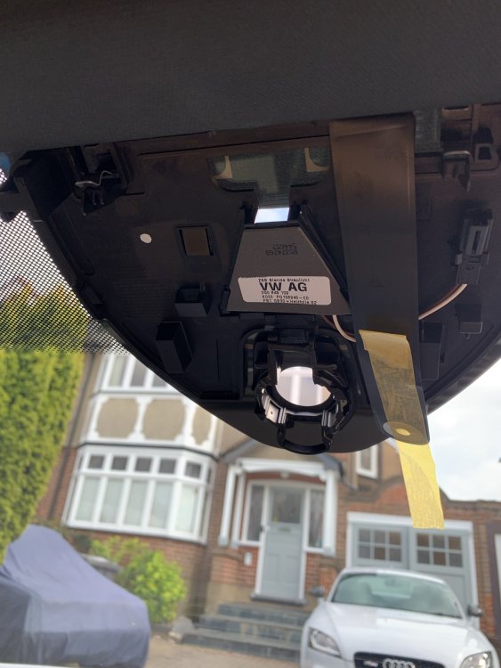
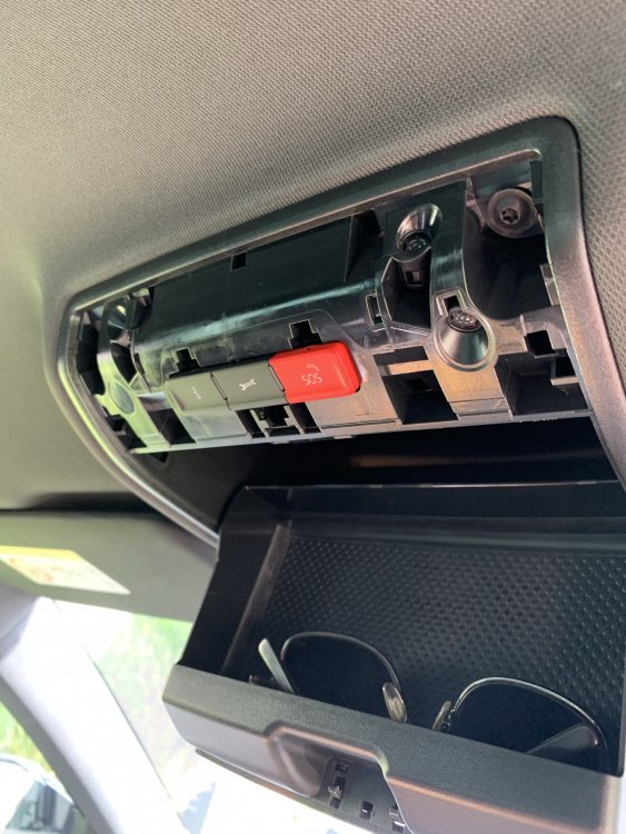
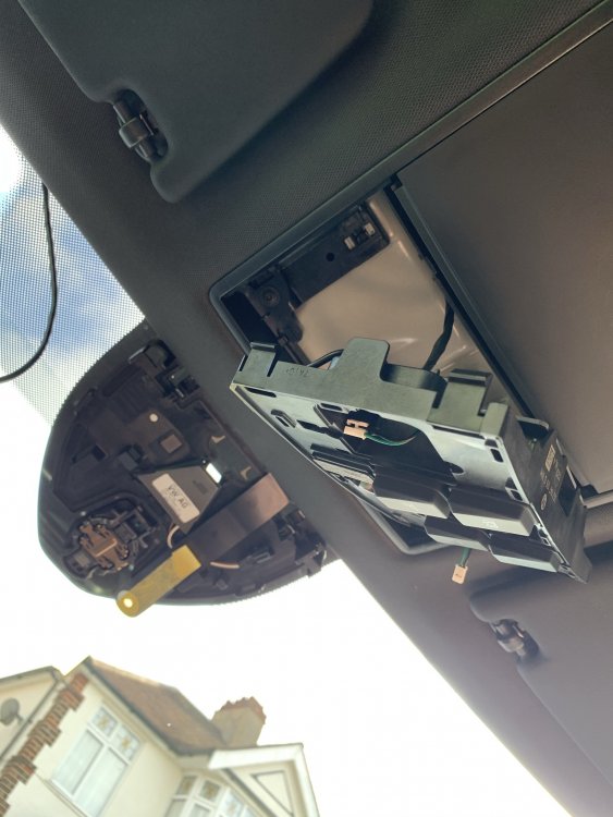
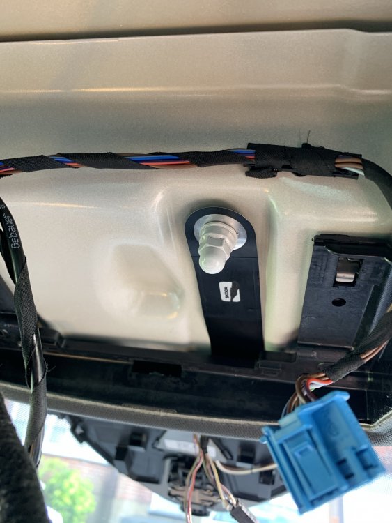
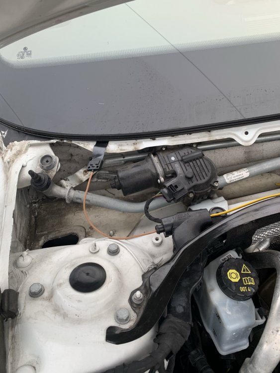
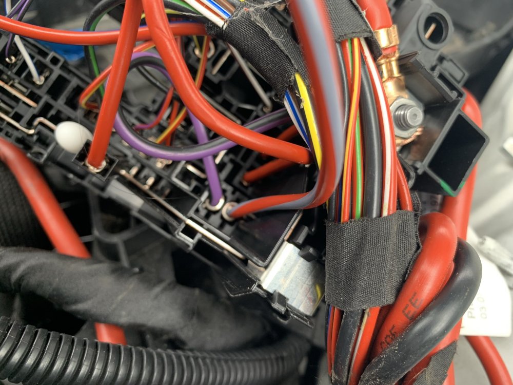
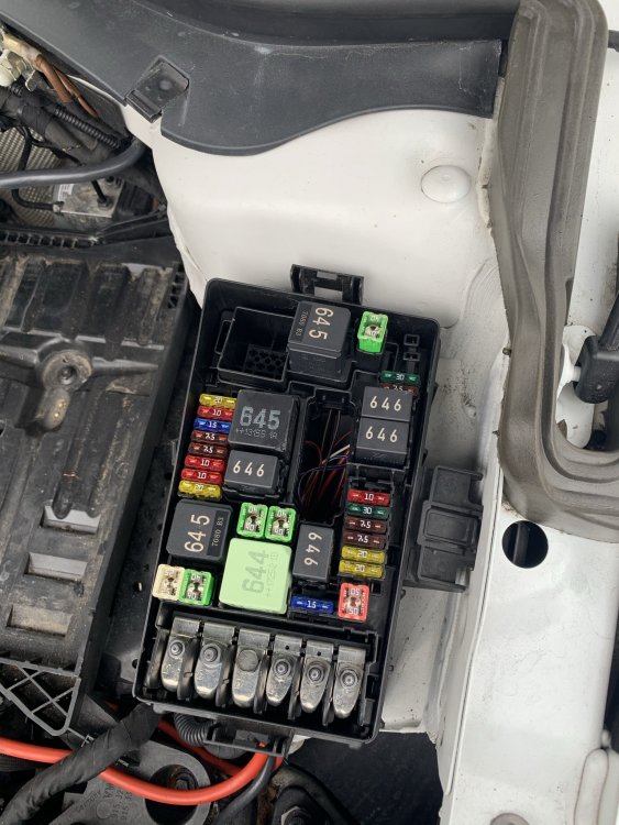
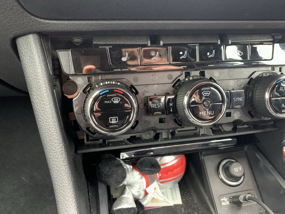
How to: Heated Windscreen Retrofit All of this is done at your own risk and is just meant as a general guide, not a full instruction manual. Just cause some things may work for my car may not mean the same for yours. Parts List 3V0845011AE - Heated Windscreen WITH A5 camera support - Will be different for everyone so confirm it first! 3V0907044DA - Dash Control Panel with heated windscreen button - Will be different for everyone so confirm it first! 071973851 x2 - Large Plug Housing for Heated screen connector 000979307E - Pins for large plug, comes with 2 pins so only order 1 000979425E - Pins for relay with 6mm wire attached, comes with 2 pins 000979027E - Pins for relay with 0.5mm wire attached. comes with 2 pins 4H0951253A - 645 Relay for main current flow 5Q0937507D - Relay holding plate, my car already came with but heres the part number 000979424E - Pins for Jtype fuse in engine bay fuse box with 6mm wire attached, comes with 2 pins N91186305 - 50A Slow blow fuse for heated screen 6mm repair wire - Only required 2 meters to be on the safe side (red) 0.5mm repair wire - Yellow/red repair wire 5m 0.5mm repair wire - Red/yellow repair wire 5m Fuse box terminal - Was not required as it splices into already used OEM pin for climate control 000979009E - Small pin for BCM plug with wire attached Varied Conduit - For wrapping the under bonnet looms to give an OEM feel and protect them Loom tape - for wrapping wiring and securing inside and outside cabin Heat shrink crimp connectors - These are genuine repair methods so order both 1mm and 6mm versions Silicone - For sealing the exterior connectors You will need VCDS & ODIS for this or equivalents. Once you have your parts together and your screen is fitted you will have 3 additional connections, 1 in the headliner, 2 at the base of the windscreen. Wiring Diagram For anyone that fancies going alone and doing the wiring themselves, here is the only wiring diagram you need. Fitting ground wire To start you'll need to drop the front interior lamp, this is done by opening the sunglasses holder and pulling the trim off around the SOS button and around the interior light buttons. Pull the interior light unit out of the housing and if need be remove the torx screws to drop the entire assembly out of the way. Here you will see the 10mm ground stud with a nut on it, remove the nut and fit your ground strap before tightening back up - DONT go crazy as it will tear the strap. Run wires through bulkhead You'll now need to run your 2x 0.5mm wires through the bulkhead, this can be fiddly so a coat hanger of some kind makes the job a lot easier, to start, remove the battery and battery tray to expose the main wiring loom which will be under a plastic cover and disapear into the passenger rear most corner of the bulkhead, the best way to do this is to poke a small hole from the outside in with the coat hanger, then from inside the car, go up under the glovebox and behind the blower motor, you will just see the end of the hanger, attach a wire to it and pull it back through. It might take a few tries to get right and just make sure you don't tear the boot or damage other wires. These 2 wires will be going from the interior fuse box area to the under bonnet fuse box so run them either inside the original loom or use some small conduit to keep them protected under the bonnet from road grime and heat. Whilst you are here, get your 6mm red wire and run it from the under bonnet fuse box area, through the plastic casing under the battery, then up the loom which heads into the scuttle panel area. Again, protect this wire with conduit or run it inside the original loom. Wire up windscreen power supply Now you have the large 6mm wire in the scuttle area, you need to remove the wiper arms which is done with 2x 13mm nuts under plastic covers, once the nuts are off, gently press on the pivot point of the wiper arm to release the entire arm making sure not to damage the screen. There are 4/5 metal clips holding the plastic scuttle covers down, these just pull off. Then starting at the outer most edge of the screen where it meets the plastic, slowly lift to remove all the plastic covers. Do this on both sides to fully expose the lower screen/scuttle area. You should now see your 2 large connectors with brown wires running into the windscreen. You will need to run your 6mm wire to both of these. You may choose a different method but mine was; place the 4mm wire with male pins inside the connector and push the purple tab inside the connector across till it clicks, I then placed the connectors in a vice and filled the rear with silicone to prevent any water getting in. The yellow wire was then cut in half. I ran the red wire all the way to the drivers side of the screen and used a OEM crimp connector to attach the 4mm wire to the 6mm wire. For the passenger side, I cut some of the insulation off the red 6mm wire near the passenger side and soldered the wires together. You will need a big soldering iron for this as the wires are massive. Both connections should be water tight. Secure the new wiring to the original loom and play close attention to making sure the drivers side connector will not make contact with the wiper motor as this will rip the wiring apart. Also make sure the connectors are not sitting in the lower section of the scuttle panel as this gets full of water, the flat part of the connectors should not be kinked either as it will damage the flat wires. Refit all the plastic trim and wiper arms - Use the dirty marks on the windscreen to line the arms back up, short wiper always goes on the passenger side. Wire up interior fuse box Next we are back inside the car and need to remove the glovebox to access the rear of the fuse box. This is done with around 8 torx screws both under and inside the glovebox, slowly lower the glovebox and make sure to disconnect all plugs. I also disconnect all plugs for the infotainment system and move the glovebox completely out of the way to give yourself more space. Now you should see your 2 wires that came through the bulkhead, we only want the red with yellow trace wire right now. Run it neatly towards the fuse box, pull the fuse box forward using the small plastic tabs giving enough room to access the back of it. At this point remove fuse 7 which is a 10A one. Find the red/yellow wire behind the fuse box that goes into fuse slot 7 it will be on the top row, this is where we want to splice our own red/yellow wire to. Make sure to use heat shrink and solder or OEM crimp connector. Place the fuse box back but DO NOT refit the fuse yet. Wire up body control module This will be our last wire under the glovebox area which is our yellow with red trace wire. You will be able to see the body control module (bcm) on the left hand side of the fuse box, it will look awkward to get to but the trick is, it doesn’t need to be fully removed. Where the lower foot well trim meets the side trim you will want to pull up on the side trim, this means you can tell pull the footwell trim out of its clip and remove it fully, once this is out the way you will see a big group of connectors we don't need any of these but instead, you should be able to see the BCM plugs directly above this group of connectors, 3 big plugs, we want the centre one, once the white locking lever is pulled down, you can pull the connector out of the unit then down a track and it will come out under the BCM area, cut the cable tie on the plug if there is one, press the 2 locking tabs in and release the inside of the plug. You will now want to run the yellow/red wire neatly to the plug you have just stripped down, attach the very small pins wire to the end of the yellow/red wire using solder or an OEM crimp connector. The plug you now have will be numbered for each pin hole, you are looking for pin location 26. Insert your pin into this until you hear a click, put the plug back together, secure your new wire to the loom and refit the plug in the opposite way to what you took apart. Refit all the trim at this point, including the glovebox unit but NOT THE FUSE - if you put the fuse back in with exposed wires under the bonnet you will blow it. Wire Up Under Bonnet Fuse Box You will now have your 3 wires at the under bonnet fuse box, you want to cut the cable tie where the wires run into the fuse box and then remove the inside section of the fuse box, this is fiddly as the little clips around the outside are a very tight fit. Once you are in and you can access the underside of the fuse box. In your parts pile you will need to find your 2 sets of repair terminals, all 4 ends will have the same terminal but 2 will be thick wires, 2 will be thin. Cut these in half so you have 4 individual wires with terminals. Attach the thin wire ones to the red/yellow and yellow/red wire. These need to be inserted into the correct relay points. Refer to the photo below which is the brown wire and yellow/red wire you see in the photo, they can go in either slot. This leaves us with 1 more red wire which runs to the windscreen, crimp one of your last 2 big terminal repair wires to it and insert into the LOWEST yellow wire point you see on the relay. Youre nearly there now! You now need to take your 2 large flat male pins with 6mm wire and you will need to cut this in half, this will leave you with 2 large male connectors and 1 large female connector all with 6mm wires. Join one of the large male and female wires together with a wire length of about 10cm. The female end will need inserting into the top relay connector which is pictured with a yellow wire. The male end will go to the fuse holder, this is shown in my picture with a red wire with grey trace and it shows where it must go, take note it will only go in one way round. The final wire which is 1 last big male terminal will need inserting next to the one you just inserted, this will give you your 2 pins for the fuse. The other end of this wire I placed securely under one of the large nuts with a red wire already attached to it. This is to supply the 12v constant supply required. This is shown pictured as a purple and black wire. Make sure all wire strands are secured and none are left to short out anywhere. At this point you can now insert your 645 relay and your 50A fuse. Put all the fuse box back together making sure no wires get caught anywhere, refit all trim, battery and everything else you took apart. You can NOW fit the 10A fuse back inside the car by just dropping the glovebox down, release the hinge on the side and with the 2 clips inside it it will lower to access the fuse board fully. That is all the wiring done! Only 2 more things to do now. Change display unit At this point you should have your new climatronics panel with the heated windscreen button. If you couldn't work out which one you needed, drop me a message. The key is 4GW = Heated front screen. First you will want to connect your VCDS to the car and SAVE YOUR CURRENT LONG CODING for module 08. If you don't do this, you'll run into trouble. Now remove the old unit, pull the plastic trim from underneath to remove it, then do the same with the actual unit no screws, just clips, remove the 3 connectors on the back and fit your new unit in the reverse order. You will notice that you cant turn the fan on or do anything with the heating yet. Don’t panic. Coding Once this is all done you can relax and just do the coding side of things now. Connect ODIS/VCDS to the vehicle and run the basic settings on the unit, this will teach the new unit your heater flap positions. Now put your old long coding back into the unit to save time and make sure everything is how it should be. You now want to open the long coding to make your modifications as follows: Byte 5 bit 0-3: 04 Windshield Glass A/C Comfort Glass [PR-4GW] Byte 11 bit 0: Windshield Defogger/Heater installed [PR-4GW] At this point, clear codes, turn the car off and lock it up for 15 minutes to allow the car to reset the canbus network. Get in, start the car and just confirm the heater is all working again as it should be. The windshield heater will not turn on but the button will flash at this point when pressed. Go to module 09 which is your BCM, Enable security access and go to your adaptations, you are looking for IDE04927-ENG142021-Window heater-Heizbare_Frontscheibe this needs to be changed from Not installed to installed. And that is it. You are all done, heated windscreen fully working. Some of you may notice the empty ADAS A5 camera spot, hopefully another guide for that will be coming in the near future as i fit it all up. Any issues with the guide or comments, let me know.


-
For the millionth time, just cause a bumper rebounds back into its original place doesnt mean damage hasnt been done underneath!!! So many people are getting caught out by this! Your radar bracket will most likely be broken or mis-shapen, it will need replacing and re calibrating at best. But could require a new radar if that is damaged itself.
-
All seems reasonable, the only thing that I dont like is the aftermarket DSG oil... Carlube is a cheap brand and just looking on ebay you can get the oil for £9 a litre so £100 for 6 litres... well you do the math. Like others have said you pay £215 for the DSG service alone at the main agent, and the service would be another £3/400 so not the worst price ive seen.
-
I got my car from Meadens in Brockenhurst and once I got it home and gave it my inspection it was far from up to standard, leaking shocks, very low tyres, damaged paint and windscreen. sadly you are out of basically all warranty periods and they won’t cover it no matter who you speak to. It’s either second hand or a brand new part required
-
So I originally had a screen fitted by a company and they ruined the job, damaged paintwork, trim and the screen they were fitting was done terribly so after months of fighting they are putting it right to the tune of just under £3000. the screen itself I am only paying the addition cost of £120 but the full price of my screen with heater and adas is roughly £670. if you drop me a pm with your car details, year, shape, what screen you currently have and what you want, I can look up the part number for you.
-
Car is at the bodyshop having a fair bit of work done, also having a Heated + Adas screen fitted to the car. Im in the process of doing a write up for the following: - A5 Camera retrofit - Heated windscreen retrofit - Heated front seats retrofit
-
Sorry but this is a load of rubbish. Driving gently or fast wont make a slight bit of difference. You can leave the car to idle for hours and it will always come out with more charge in the battery than you started with... If youre having issues like that, your car has the issues, they arent designed to not have enough power?
-
Please put it in a [code] or quote tag so it’s not a million miles long 😂 did you save any backups from before you modified anything and what’s the actual problem you’re having
-
It can only be done with odis and a valid geko security account. this is needed for key coding and component protection
-
Correct, brembo oem is made by brembo, aftermarket brembo is just a brand name which in my opinion the quality is awful and they get lots of complaints of noise
-
Just fit a set of pagid brakes, good quality. don’t go for the budget crap like eicher or brembo
-
Cruise control uses engine braking and normal hydraulic braking. It won’t just brake the rears.
-
Use obd11 to check the brake pedal sensor and if you have a clutch pedal sensor
-
Go to Halfords and get their premium mats that are fitted. £45 Ish and they are really good quality, if you wear a hole through them, they replace free of charge
-
Yes, for the electric handbrake you need a diagnostic computer capable of winding it back.
-
There is lots more involved, it needs to be started with a genuine copy of odis to remove component protection, modules will need coding to adjust for the new unit, possibly the display needs changing and i might be wrong on this but if your car doesnt have satnav, it might not have the correct antennas there.
-
Definitely won’t be 90 litres! That would cost like £130 to fill up
-
-
No, you need a diagnostic tool to do the vent routine.
-
So instead of a thermostat on these engines it uses a 'variable' water pump, the varaible side loves to seize up on them. Needs a timing belt and water pump replacement but you should also check the radiator fan is running - this can be done by switching the air con on and it should start spinning. Replacing the water pump has 2 options, go genuine/standard and you will need to run a purge routine after replacement, other option is some companies now sell a water pump with no shroud to prevent this issue, also means your engine will take a lot longer to get up to temp
-
I didn’t look at the link but yes you are correct. The annoying thing is, this still might not come with all the features he is after as some of it requires SWaP codes
-
So if the car comes with just high beam assist, it will come with a small low level camera, this can’t do anything else. to change to the high line camera often referred to as A5 camera means a new windscreen; lots of wiring, parts and coding. to fit pACC you would also need to upgrade the Acc radar, have it coded and recalibrated. none of this is cheap or easy sadly
-
Lots of police forces use superbs, some saloon, some estate. they are far from standard spec too, although l&k is often used as the base model for the 4wd and 280 engine the interior is often a lot more basic and more like the SE models, often with cloth interior, basic radios and not much else, all in an effort to keep cost down. that being said, they also do an armoured version with inch thick glass, armoured all round and you wouldn’t be able to tell it apart from a normal Skoda superb on the side of the road.