
xman
Resident Member
-
Joined
-
Last visited
Everything posted by xman
-
Police are normally only interested if someone was injured. I doubt that they would raise a NIP about a car park bump, they would just advise the "victim" to contact their insurance company. They would also contact you directly, usually a visit by a policeman, to gather evidence before a NIP can be issued. They would want to establish that you were the driver of the vehicle. So double and triple check this NIP is genuine and dont rely on the contact details given on the letter. Many sophisticated scams out there. A car park bump would at most involve insurance companies. If no one has contacted you from an insurance company,suspect a scam. Note that a hospital car park is private property too so police have very limited powers regarding traffic accidents. If its genuine it suggests they have video footage of you hitting a pedestrian. Another possibility is a witness got the number plate wrong, or confused/guessed part of it. If its a genuine hit and run where the offending vehicle sped off, maybe witnesses were garnered after the event and asked if they could remember any number plate of the "car that just left a minute or two ago" and yours got offered up and no further checks as to make or model was made. Fingers crossed it turns out well.
-
Afaik, for rear EPB, no winding back or pushing pistons is needed. Its actually quicker and easier to change the rear pads and discs than with old fashioned manual handbrakes. Provided you can trigger service mode with an appropriate diagnostic tool that is.
-
The EPB (electronic parking brake) needs to fully retract the pads in order to have adequate room to fit new discs and pads. So it needs to be placed into a special brake service mode by VCDS, OBDeleven, Carista or several other such diagnostic tools which can access and activate this mode. Releasing the EPB from the internal handbrake control lifts the pads off the discs by just a small amount so if the pads and discs are worn there would be insufficient room to replace them with new full thickness parts. After replacement, service mode has to be reset and the EPB will adjust positions automatically to the new parts and resume normal operation. Hope that explanation helps.
-
The what car article (sponsored by Nissan btw) is dated 22Feb 2019, so is somewhat out of date. Quite a few prices have increased in 2 years. Shell recharge for instance has gone up from 25p to 39p per kwh.
-
On a stop/start equipped car, the negative terminal connector on the battery lead has an inbuilt current sensor which accurately monitors current going in and out of the battery. The battery management needs this to track of state of charge (SOC) and with voltage monitoring, also deduce the health of the battery (SOH). It forms a crucial part of the micro hybrid charge management. If you connect a charger or jumper leads directly to the negative battery terminal, you bypass the sensor, the battery management loses track of the true state of charge in the battery which leads to problems with stop/start and ultimately shortens battery life. https://www.yuasa.co.uk/info/technical/micro-hybrid-hybrid-vehicles-explained/
-
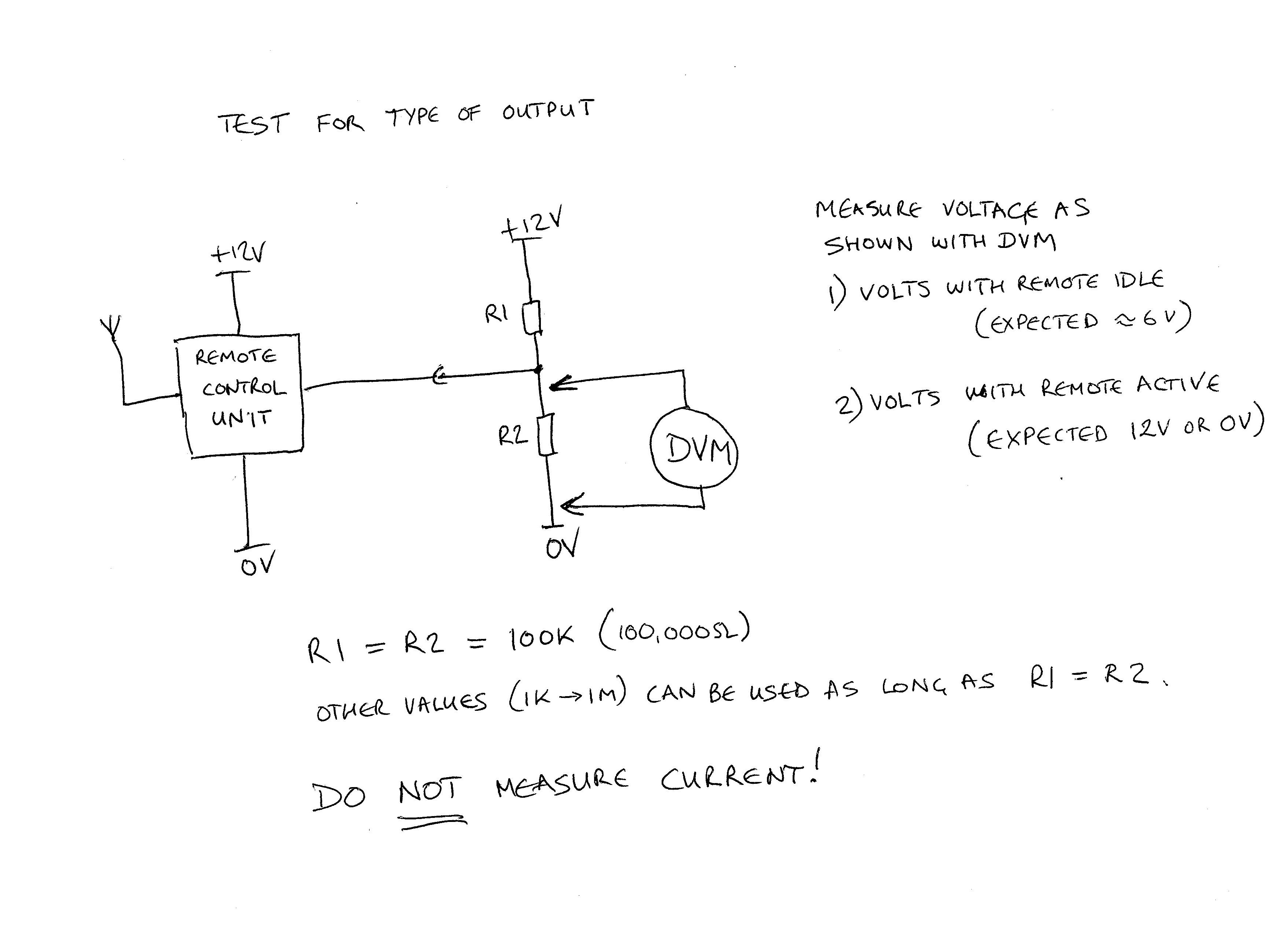
First let me advise you - do NOT take any current measurements - you risk blowing components, it may be the reason the remote c/l unit is only outputting 25mV as you may have blown a transistor internally. We only need voltage measurements. I am trying to establish a few fundamental things first, assuming the remote unit output is not damaged, it may have what is known as an open collector output, to test for that, please follow the instructions in the diagram below and post your results. If it is as suspected then a simple pull up or pull down resistor will give us a large healthy signal. Your design is over complex with many errors, the transistors (underrated btw) wont last very long switching inductive relay coils without protection diodes, to name but one error. But if we can establish what the remote unit output is doing then I'm sure we can sort out a much simpler circuit.

-
Well there's quite a lot wrong with that design. It would help if you could supply further information. 1. Some info about the C/L unit - a spec sheet, link to a webpage, part number whatever. I've a feeling you've missed that the output you are using to trigger is an open collector type output. 2. Relay info - coil resistance and operating voltage (or a part no) 3. Not sure what that diode is doing in the op-amp feedback, is it a diode or a LED? 4. Opamp part no. I must pass comment that I think its highly optimistic for you to think your motor will always park in the same position, given variables like voltage, load, temperature etc and what would you do if it stops in the wrong position but once I've got the info above I'll sketch out a circuit that should work as you originally wanted based on the bits you already have. I'll add some notes to explain various things you may not be aware of that you need that are missing.
-
Yes, the trigger must not float. It must also return to high state before the output returns low. Also the trigger threshold voltages must be exceeded (<27% VDD to trigger, return >72% VDD) this may be a problem if the input trigger voltage does not comply (drawing suggests a 9 volt source) in which case an additional voltage translation stage may be required.
-
Describe exactly what you are aiming to do. Hand draw your complete circuit with the output transistor etc, I can suggest a correct circuit design based on your 555, with appropriate additional components to protect it in an automotive application. In particular show what load you are driving and how (bipolar/mosfet etc) and why 2.05 seconds is critical. Also describe the input trigger signal from your external control unit, high/low voltage levels, duration of trigger pulse supplied, high to low edge trigger etc The 100 ohm resistor you connected in line with the battery drops voltage if any current is taken from pin 3, and so creates an unstable supply voltage to the IC and its timing side RC so it will have unpredictable behaviour, such as oscilliating. Supply voltages to ICs should always be stable and (capacitor) decoupled to ensure correct operation. NE555 is a 40 year old design, there are more recent CMOS equivalents that have much lower power draw, ICM7555 etc You have selected a rather ridiculous RC arrangement, electrolytic capacitors are not great in timing applications, most have ±20% tolerance and leakage is a problem in high capacitance electrolytics. Before any one asks for my qualifications, I have active been in industrial electronics/micro design for almost 50 years.....
-
All I can say is if anyone is stupid enough to follow the advice of sticking a hairdryer on high setting inside their LED headlight and leaving it there for 15 mins to cook, and suffers any subsequent problems they can send the bill for replacements to J.R.
-
If you take a hair dryer apart you will see the heater element is mounted inside a mica tube that shields and protects the plastic shell from the heat of the elements. If you restrict air flow , as you would in the suggested method above, the elements will glow red hot, and the air going into the lamp would easily get hot enough to damage silvering on plastics and much more. Please be my guest and try it on a Skoda plastic led headlight, they are only 600 euro each from Skoda-parts.com if you should damage it.
-
Don't follow this advice!! A hairdryer on high in a confined space reaches a very high temperature! You will almost certainly damage the headlight internally, melting/distorting the plasic internals and internal moving parts and damage the LED unit, wiring and optics. It will cost you several hundred pounds per side to replace LED headlights. In any case it will not solve the problem because the units are ventilated, not sealed and outside air/humidity invariably gets drawn in and misting will happen when there is humidity and a temperature difference inside/outside the unit. Its a design consequence and theres no easy fix.
-
Get the battery checked first, a knackered or flat/low battery often leads to the power steering assistance switching off.
-
Thanks for the cordial reply, the bending out of shape comes from the political socialist EU claptrap and constant insulting language being posted elsewhere by less than half a dozen members, going on now for years. I think you probably know who I mean. Have a happy and prosperous new year @J.R. and everyone else.
-
Usual robust but somewhat misguided reply from Monsieur jr. Most car engines of any type when cruising produce very little power, just enough to overcome rolling resistance and aerodynamics. Many many, members have 3 pot non turbo fabias, I have one for example, it is rated at 70ps at 5500 rpm, never ever been anywhere near full output level even at 70 mph (3500rpm) 1 litre of petrol contains 9.1kWh of energy. At 40mph, lots of petrol engined cars will do 50 mpg i.e. in one hour use 3.64 litres or 33 kWh of energy, petrol engines are around 30% efficient at best so thats 10kWh power developed, tying up with what EV's are reporting as typical energy useage. Soon be new year, and I will be leaving Briskoda, so no need to reply.
-
A battery is not a resistive load (neither are many of the other current consumers) so Ohm's law is of no use, The main controlling sensor (used in a negative feedback control loop configuration) is the current sensor on the battery, and if that fails (or someone disconnects it), the system will revert to an old fashioned fixed voltage (temperature compensated) charge system.
-
Lets check then..... EV's often quoted as achieving 3 to 4 miles per kWh (includes ancillaries/battery/convertor/motor losses) Lets assume 4 miles achieved for 1 kWh of output power at the motor, that's probably on the low side. 40 mph average for a hour therfore requires 10kWh 120A 14.3v alternator is 1.7kW Up to 10% requirement (1kW) therefore 70A from the alternator
-
Using the current sensor in a negative feedback loop to control current and yes the voltage will vary, but because of good charge acceptance at the battery, it only takes a little extra voltage to increase current into the battery significantly. Most of the time e.g. when cruising at constant speed, if the the SOC is on target (say 80%) the battery will not be charging and the voltage will fall back to a level where only the active current consumers are being supplied. I have not looked at the alternators on these cars, but the inbuilt regulators must be completely different allowing the voltage and current to be controlled externally, maybe even via a digital channel.
-
I think the charging system is probably based mainly on controlling current going into and out of the battery using feedback from the current sensor mounted on the negative terminal. It can track charge (coulomb counting) and so be able to maintain/increase/decrease the batteries SOC, whatever the battery management system demands at any moment EFB and AGM batteries have considerably greater charge acceptance ability than old conventional lead acid batteries so you won't necessarily see large increases in voltages with charge current although its likely the alternator can allow the voltage to rise higher if demanded by the battery management to maintain current flow e.g. when the battery is older and/or knackered
-
What car and what tyres were they?
-
Maybe he's refering to the "flow transformer" device thats fitted to reduce swirl.
-
Not sure this is the correct forum for this but here goes.... Have you ever wondered about how MOT brake tests are done? Rolling roads and all that. Well, as my Superb is due shortly I wondered about how an EPB (Electric Parking Brake) would be tested given they are pretty much fully locked/unlocked devices. Found this article on EPB MOT testing..... http://www.partinfo.co.uk/articles/75 So it raises a few questions especially if using an independent or non franchised Skoda dealer to do the MOT. Are they aware of the correct methods to employ when a car has an EPB, Haldex or a DSG box? All of these could be damaged if they just try to drag the wheels on their roller tester without following the correct manufacturer/model specific instructions. Would they even be aware that any special procedure should be used? I don't know the answers, or just how much damage is possible, but it set me off thinkig. Is it worth risking using an independent MOT centre if your car has an EPB, Haldex, or a DSG?
-
It would be interesting to compare "basic led headlights" as fitted as standard to the "matrix led headlights" which are are a ridiculously expensive (~£1400) option. I suspect the basic led headlights are not self levelling and don't have washers, so they are restricted to a 2000 lumen max output in the ECE regs. Standard Xenon lights with self levelling etc are 3200 lumens. I expect the matrix leds will be similar or better. For comparison, legal H7 (55w) halogen bulbs have a 1500 lumen output. As for the groaning brake release problem, does the OP have Hill hold? This differs from Autohold in that it holds the brakes on inclines for 1 to 2 secs after the accelerator is applied before releasing. I don't really know much more than that.
-
This was never a problem I've seen in any headlight in over 40 years of driving and countless cars including a mk1 fabia, 2 x mk2 fabias and a mk2 fl octavia all of which had plastic headlamps. My mk3 superb 2018 however suffers from this as do many others in the mk3 forum, and Skoda just glibly says this is normal and not a warranty issue. I say bull. The condensation will eventually stain/dirty/corrode the internals/optics in the headlight.
-
In the distant past Direct line simply suspended my policy, and even gave a refund for the period the paid up insurance was suspended subject to a minimum of six weeks iirc. Actually suspended it for several months and got a couple of hundred pounds refunded. Would need to check if this is still the case.