varooom
Resident Member
-
Joined
-
Last visited
Everything posted by varooom
-
Probably naff maps, not programmed right and get's it wrong.
-
Are you near any parallel roads when this occurs, as could be flipping you between the 2 roads?
-
@sansuy You should check out this thread for new maps https://www.briskoda.net/forums/topic/504028-amundsen-mib2-map-updates-2023/ I think you unit is Amundsen, but could be wrong. The VW maps are same for Skoda/Seat
-
I can send you a private message in next few minutes. Switzerland right?
-
Everything in the car is measure in metric, so no a quick change just for us that work in Miles. Issue is caused when someone just accepted the default values in the computer of 15,000 Km and didn't change it to 16,090 Km (something like that) You can ignore the demand to service now, or get someone to go in and adjust the values, like using VCDS. When it does go in, make sure to state you want it set to 16,000Km for your full 10,000 Miles.
-
Hello and welcome, You should have probably posted in this large firmware thread https://www.briskoda.net/forums/topic/477657-amundsen-mib2-firmware-update/page/70/ I shall need you to find me the Software Train version, use this video to look up your value MIB Infotainment version check (MIB1 MIB2 MIB2.5 MIB2Std MIB2High) I think you have MST2_EU_SK_ZR_P0367T, and MST2_EU_SK_ZR_P0369T is available if this is the case.
-
If you do go ahead, report back any campaign(s) listed. And a dealer has same information, so should check their computer and action it (pay attention to the list of "customer compaints" and drop some of those in a conversation with front desk, they should search, failing that demand XXYY campaign be sorted!)
-
Long life service will be variable, sensor based or how you drive it. (I think max is 30,000Km) Fixed service is what yours is on, and it's set to 15,000Km iirc so calculates to around 9,400 Miles give or take a little. VAG measure in Km in servicing.
-
MST2_EU_SE_ZR_P0516T is available for your SEAT Maps could be updated too by the looks of your data level there
-
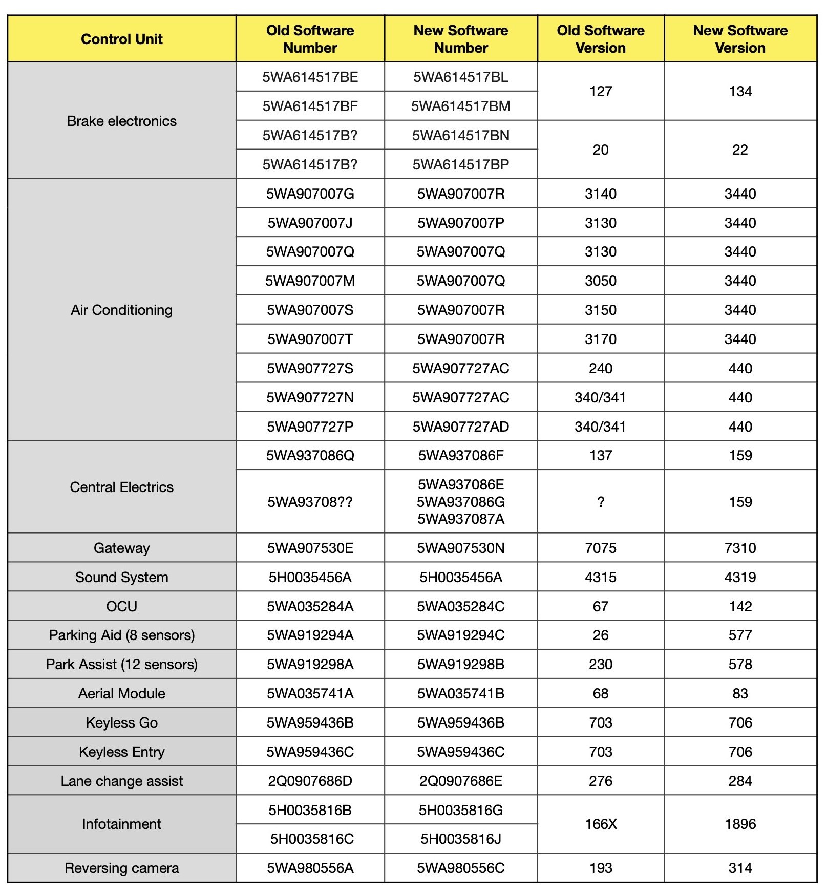
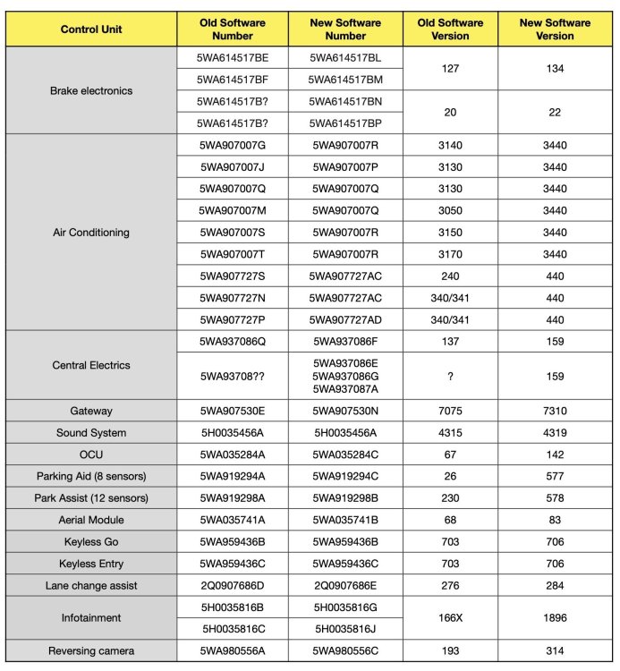
For a fairly low fee, you could make account on https://erwin.skoda-auto.cz/erwin/showHome.do there you can input your VIN, and if there are any outstanding campaigns they will be flagged to you. You can download a list of PR Codes fitted to your car (handy for when you are buying parts to check if they actually fit your car) You can download wiring diagrams/repair information if you are planning on keeping the car for a few more years, will be helpful for repairs. This was lifted from a VW Golf Mk8 forum, and this references the famous SW1896 software update for the MMI unit. You may find that the parts fitted to a Golf are also on your Skoda... no real surprise there. Main takeaway for this, is you can see just how many modules have to get the SW updated, and Brake electronics is part of this equation. So you can visit the erWin site armed with your VIN and bank card to get any campaign(s) outstanding on your car, and the visit won't be wasted as you can grab wiring diagrams/repair manuals. Money well spent IMHO.
-
I am by no means an expert, but an armchair mechanic who likes to spin the spanners myself. The low Voltages are a very common theme you are correct, now if you read your massive fault lot (so many!) you can see you have times when your engine is running, but you have 10.7V at Terminal 30. In some fault codes with engine running you have 14V at Terminal 30. This little beauty looks brilliant, only 7.503 Volts Address 05: Acc/Start Auth. (J518) Labels:| 5Q0-959-435.clb Part No SW: 3Q0 959 435 G HW: 3Q0 959 435 G Component: VWKESSYMQB 037 0906 Revision: 00037000 Serial number: 0449725122 Coding: 032C0C070F Shop #: WSC 33361 790 00141 ASAM Dataset: EV_KessyHellaMQBAB 004041 ROD: EV_KessyHellaMQBAB.rod VCID: 3E26364990FA78ABFD3-806A Rear lid opener control module: Subsystem 1 - Part No SW: 3AA 962 243 G HW: 3AA 962 243 G Component: GEB.F.Heckoef H16 0903 Serial number: 84519619 1 Fault Found: 65794 - Function Restricted due to Insufficient Voltage U1400 00 [008] - - [Function restriction due to temp low voltage] Intermittent - Confirmed - Tested Since Memory Clear Freeze Frame: Fault Status: 00000001 Fault Priority: 6 Reset counter: 158 Mileage: 70430 km Date: 2021.05.07 Time: 16:14:38 Control Module Voltage: 7.503 V Vehicle speed: 0.0 km/h Engine RPM: 0.0 /min Status of vehicle locking: Vehicle unlocked Driver door: closed Front Passenger Door: Open If the car had this little amount of Voltage, what happened that day? Did you need to jumpstart the car? There are instances with the engine running, and you have as I mentioned only 10.7 Volts, odds are it took a bit of effort to start it. The next thing is the dates of the faults, some go back to 2021.05, so it would appear it's been having a bit of trouble for a while now. Given that low Voltage will put errors up in a lot of control modules, it might be worth resetting all the fault codes and see what comes up right away, and over the course of a few days/weeks as needed. It's probably a duff battery, or you have a parasitic drain sucking down power during the night... have you had the battery checked?
-
Yeah he has that thankfully
-
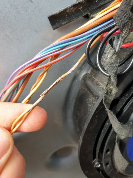
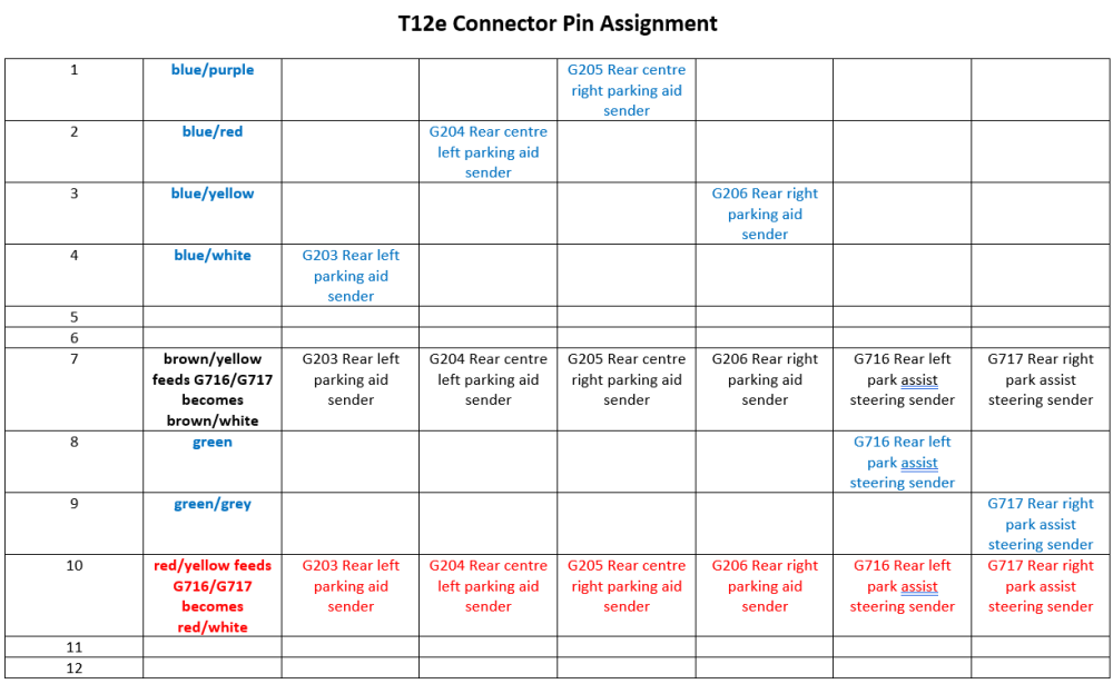
Credits to @Breezy_Pete & @JoeF for both posting this image This shows us an image of a single wire that is spliced into two wires Step 7: Here we have a tracing of all the wires in the loom from T12e to each of the 6x Sensors Red text is for the Positive (only 1 feed wire is Positive, T12e / 10) Black for Negative (only 1 feed wire is Negative, T12e / 7) Blue for Sensor data (T12e / 1-4, 8 & 9) Step 8: So how do we actually know where to look for a fault in the wiring loom? This is where you must combine the knowledge of the wiring diagram and also the fault codes that we scanned. If there was a fault in the main wiring loom from the module J791 via T26b (short to ground for example) then we can see that this would take out ALL 6 sensors, not just 3 out of the 6 Now we know that from T12e down to each sensor in turn is just 1 Positive feed, and 1 Negative feed wire, and where each of these 2x main feed wires then are spliced down towards each of the sensors. We can now disconnect connector T12e from inside of the boot on the left (behind tail light, inside the body) and check each sensor that is faulting, by disconnecting the wire and checking for continuity from T12e pin 10 to the Positive and Negative on each sensor. We can also visually inspect of course to see if any wires are cut, before we even have to probe any wires. In the above example, 3 of the 6 sensors cannot communicate. And checking the wires, breaks can be seen in some with corrosion, and also with some wires where no corrosion is seen, upon stripping the loom wires can be found to have been shorted out. Therefore, repair or replace this loom section (in this example, new loom fitted due to water ingress on some of the plugs)
-
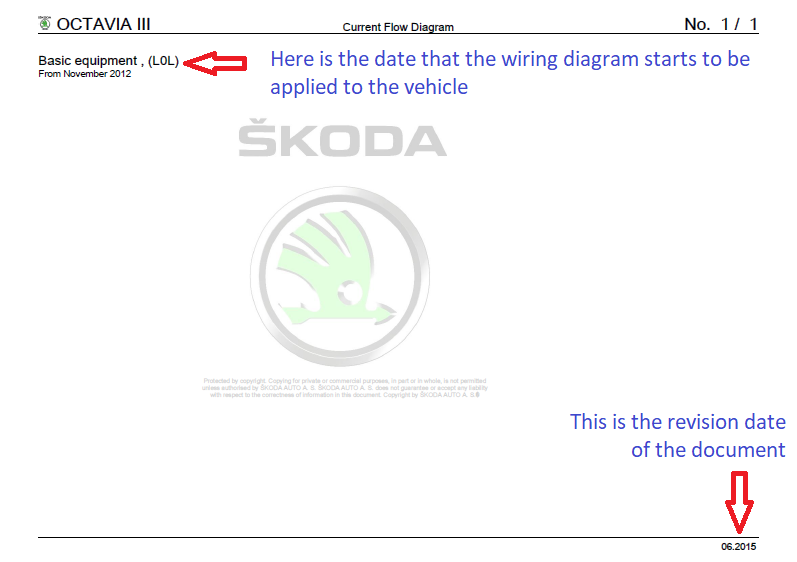
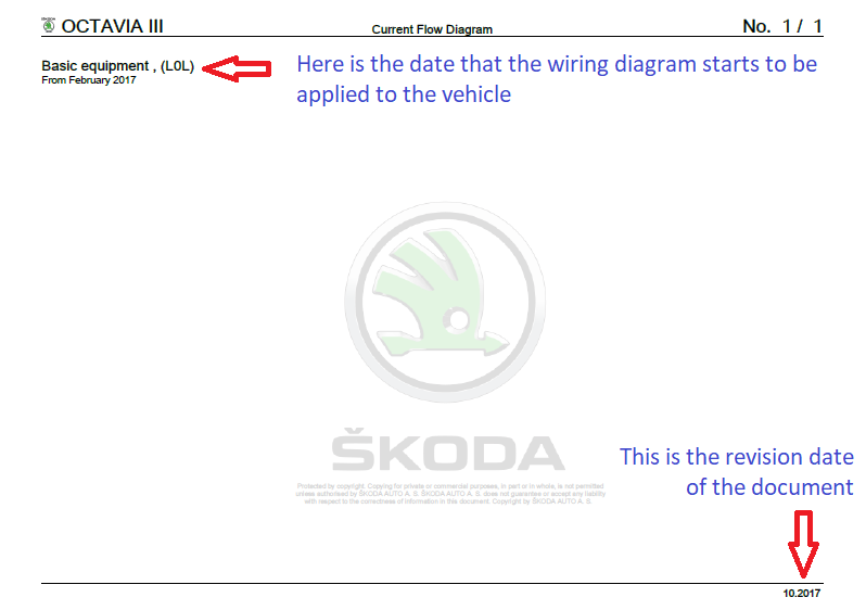
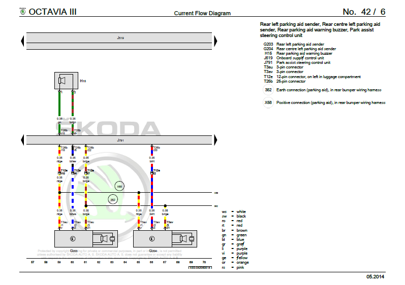
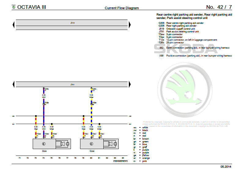
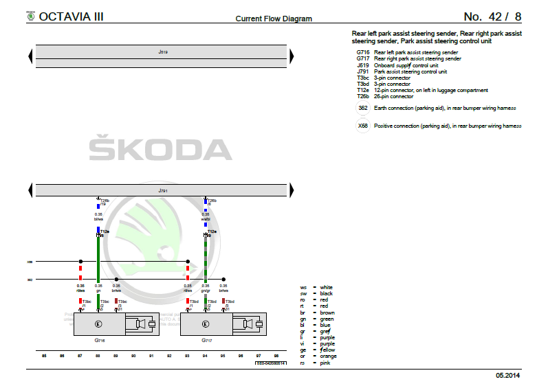
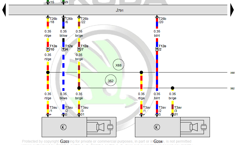
I am going to show you an example of a real life issue, and how you can then use this to locate and read the wiring diagram to help you trace faulty wiring. The car in question is a 2015 Skoda Octavia III Step 1: The car is scanned and we save this diagnostic session (because car history is important to keep) Address 10: Park/Steer Assist (J791) Labels:| 5Q0-919-298.clb Part No SW: 5Q0 919 298 K HW: 5Q0 919 298 Component: PARKHILFE PLA H12 0054 Revision: -------- Serial number: 39491514005930 Coding: 0131061041 Shop #: WSC 73430 790 00063 ASAM Dataset: EV_EPHVA2CAU3700000 003021 ROD: EV_EPHVA2CAU3700000_003.rod VCID: 47992422FE9974B74E-8012 3 Faults Found: 1079572 - Rear Right Parking Aid Sensors B1079 14 [009] - Open or Short to Ground Confirmed - Tested Since Memory Clear Freeze Frame: Fault Status: 00000001 Fault Priority: 3 Fault Frequency: 2 Reset counter: 98 Mileage: 222684 km Date: 2021.04.19 Time: 14:36:26 1079316 - Center Rear Right Parking Aid Sensor B1078 14 [009] - Open or Short to Ground Confirmed - Tested Since Memory Clear Freeze Frame: Fault Status: 00000001 Fault Priority: 3 Fault Frequency: 1 Reset counter: 2 Mileage: 222684 km Date: 2021.04.19 Time: 14:36:26 1080852 - Side Rear Right Parking Aid Sensors B107E 14 [009] - Open or Short to Ground Confirmed - Tested Since Memory Clear Freeze Frame: Fault Status: 00000001 Fault Priority: 3 Fault Frequency: 1 Reset counter: 2 Mileage: 222684 km Date: 2021.04.19 Time: 14:36:27 Step 2: We need to locate the correct wiring diagram, this is for an Octavia III 2015 car You will note from the next 2 pictures, that there exists two wiring diagram files from erWin website Here is the second file... As you can see from these two documents, the correct file we need to search though is our 1st document, as it "from November 2012" onwards Step 3: We now need to search the document for a keyword, or we need to use the bookmarks to find the correct section If you remember our diagnostic log, we can take the name of the control module scanned and use that as our keyword Address 10: Park/Steer Assist (J791) Labels:| 5Q0-919-298.clb For our example, we have J791 we can input into a search field on the document This takes us to this main section Step 4: We will now need to scan through the next few pages until we find the correct wiring diagram, which will depend on what is fitted to the vehicle The car in question has 6x rear parking sensors, and some of the pages only show wiring for 4x sensors! Diagram No. 42 / 6 This shows 2 of the 6 sensors, G203 and G204 Diagram No. 42 / 7 This shows the next pair of 2 sensors, G205 and G206 Diagram No. 42 / 8 This shows final 2 of the 6 sensors, G716 and G717 Step 5: Now the hardest part is tying all 3 wiring diagrams together. If we start with the basics, along the bottom row, each image has got a line, along with a row of numbers at the bottom, this is what ties one page into another so you can follow the trail of breadcrumbs so to speak. Diagram No. 42 / 6 Diagram No. 42 / 7 Diagram No. 42 / 8 So if you can imagine printing out all 3x pages, you would have to lay these 3x pages from left to right in a linear fashion. Step 6a: Now we need to examine and work out in our example, how each of the sensors is connected to the Park/Steer Assist (J791) module Taking a look at this small section: - Our module J791 is at the top, it connects towards our sensor via T26b connector (the numerical value = number of connections in the plug) T26b then connects to T12e 12-pin connector, on left in luggage compartment. Finally we have T3au that is the small 3-pin plug that connects onto the parking sensor itself Ok, so that was just one section of the wiring from the control unit J791 to just one sensor Now if we look at the 3x wires that head down to the sensor, we see on connector T3au/1 (left) and T3au/3 (right) two large black dots, along with a black horizontal line heading off to the right side of the image. The line coming from connector T3au/1 (left) has a large circled X68 Positive connection (parking aid), in rear bumper wiring harness This means that the wire coming from T12e/10 towards T3au/1 will have a "splice connection" where the single feed wire is split into two or more cables The line coming from connector T3au/3 (right) has a large circled 352 Earth connection (parking aid), in rear bumper wiring harness This means that the wire coming from T12e/10 towards T3au/3 will have a "splice connection" where the single feed wire is split into two or more cables I will add at the bottom of the thread, what a splice connection looks like in real life Step 6b: We now need to follow onto the next two pages of the documents to make note of what wires go where. Here is something that should be obvious, but best to point this out. The connector T12e is named so as it only has 12 maximum connections Each of the sensors has 3 wires feeding it Given that there are 6 sensors in total for this example vehicle, you can multiply 3 wires per sensor, and 6 sensors for a grand total of "18" wires Last time I checked, 18 wires cannot go into a 12 pin connector So this is why the little black dots on the wiring diagram and the circled X68 & 352 are important, they represent a splice in the wiring.


-
If eurolites are something to cover up the left side kick up, then yes.
-
Welcome, car looks lovely.
-
Apologies for not say welcome The likes of VCDS/OBD11 can change lots of settings in the car. It might be a good idea to try to locate a local user with one of the tools to see if they can adjust some values, if you decide not to buy either tool If you sniff around in the Amundsen menu's you can probably get up the Software Train value and feed it back to the usual thread. This is the firmware inside the unit, and more than likely an update is available.
-
Ah you wrote afternoon here, with no mention of change to evening.
-
You may want to try and adjust the lighting at night with the headlights on and see how you get on. A lot of the new cars are being chucked out too fast, and software glitches are the norm sadly.
-
A definitive left kickup.
-
@Misant44 version 0480 is available, I can send you a PM in 5 minutes.
-
I don't suppose you have a full VCDS read out for your car?
-
I've taken mechanic's tools for a ride also.
-
I think that you can get all your codes, certainly you will be able to see if there are any active campaigns running. You can also get wiring diagrams/repair information.
-
Yeah that doesn't feel natural to me neither.