nige8021
Members
-
Joined
-
Last visited
Everything posted by nige8021
-
https://skoda.7zap.com/en/cz/octavia/oct/2013-663/9/953-953050/#2 (2) ??
-
http://wiki.ross-tech.com/wiki/index.php/Cruise_Control_Retrofitting_(1K) & for part #'s https://skoda.7zap.com/en/cz/
-
Open the bonnet & hatch then measure gap, that is the maximum length you can fit without having access problems
-
The RPM signal will be part of the CanBus signal from the ECU to the speedo so not a simple single wire like on the older cars but as said there will be a rev limiter built into the OEM ECU but it might not be at the RPM you want, so you'd have to get the ECU re-mapped to the required RPM
-
The procedure is shown in this http://wiki.ross-tech.com/wiki/index.php/Immobilizer Gen 2 Immob http://wiki.ross-tech.com/wiki/index.php/Immobilizer_II_Key_Matching_(Cluster) You will need VagTacho or VagCommander to get the 4 digit PIN to be able to use the shown method
-
The non remote key will still need the immob chip programming to match the cars immob unit, Timpsons say they can do this for most cars, I enquired about 5 years ago and it was going to be around £50 still a lot cheaper than the main stealership but in the end I got a key cut from an eBay seller £10 and a virgin chip £5 then with VagTacho pulled the PIN code from the immob and with VCDS programmed the chip myself
-
There is a guy on Instagram Vagretofits ? based in Bulgaria I think does this sort of things remotely ??
-
When I replaced the LEDs in my MK1 Octy I went from green to blue as they are the same voltage (3.4v) and I think I bought them from Farnell or it might of been eBay, there's a PDF in the MK1 section about how to replace them, including the sizes assuming they are the same for the MK2 ??
-
If you fit Red instead of white you will also need to change the resistor as the different colours operate at different voltages 2.1v for red & 3.4 for white so just fitting red LEDs will fry them quite quickly
-
Have a look at this there might be someone near you ?
-
Sounds like classic case of the turbo vanes sticking, a fault code readout would confirm it, but search for Mr Muscle turbo cleaning loads of posts about it and youtube guides on how to do it.
-
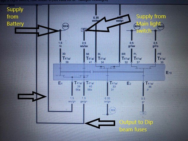
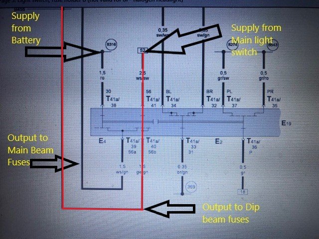
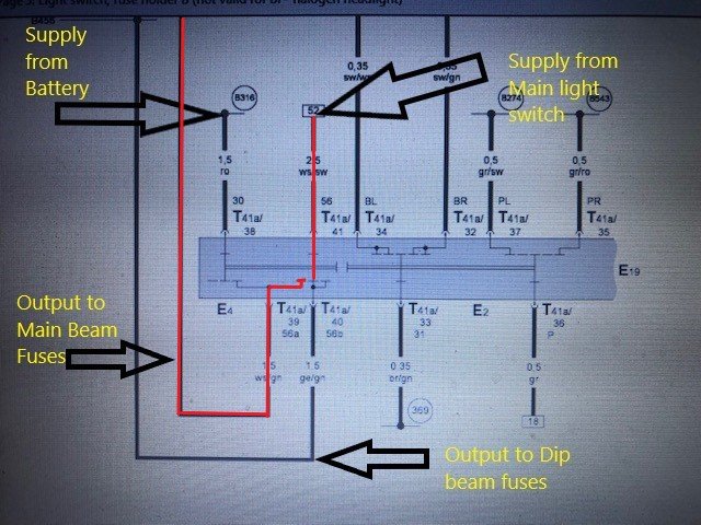
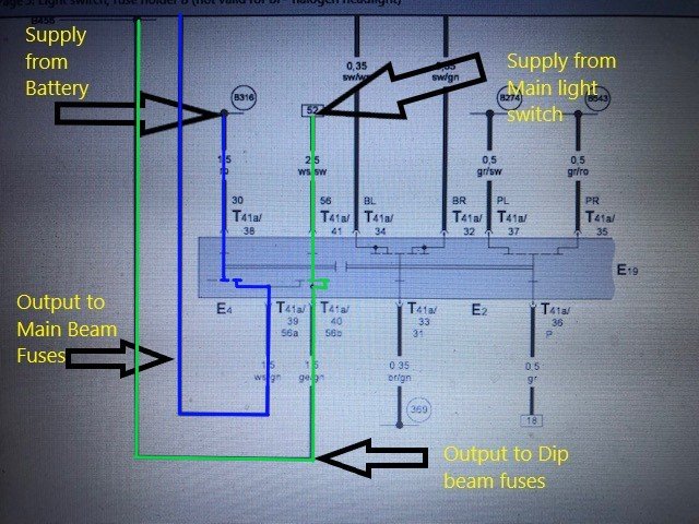
The above is the normal current flow for the dipped beam The above is the normal current flow for the Main beam (note the same supply as the dipped beam) The above is when the pull for "Flash" the Blue line is for the Main beam & the Green line is if the main light switch is selected to headlights there is also a supply then to the dipped beam as well as the separate supply to the main beam
-
-
If the main beam is working it blows your theory that it's the main light switch out of the water as it's the same supply that feeds both dip & main only the "Flash" uses a different supply and from experience of many VAG models the contacts in the stalk switch are the most common fail item
-
Obviously you can't read a circuit diagram, if you could you would see there are two contacts inside the stalk switch that are the current path to the dipped beam fuses, therefore the stalk switch does have an effect on the operation of the dip beam circuit and the main beam normal circuit is powered by the same source as the dipped beam it is only the main beam flash that is separate from the Hi/Lo beam function of the stalk switch
-
-
-
-
If it was available I think it would be in this diagram https://skoda.7zap.com/en/cz/octavia/oct/2003-252/8/823-823010/ #5 are the two scuttle panels #8 is the rubber trim that goes over the front edge of #5 and nothing in this diagram for the windscreen https://skoda.7zap.com/en/cz/octavia/oct/2003-252/8/845-845000/
-
Have a look at this
-
Yeah disconnect the cable from the aerial base and on the connector for the coax from the radio, red test lead on the centre pin and black/common on the outer, if you don't get any voltage try the black lead to the car chassis the tailgate hinge points should be a good place, if you then have voltage the outer/screening of the aerial cable or the connector is at fault
-
Did you check for voltage at the aerial connector yet ?
-
No the connector coming from the radio that connects onto the aerial base, that should have 12v between the centre conductor and the outer screen or ground
-
Should be 12v coming out of the aerial connector
-
Have you checked you are getting 12v at the aerial end of the aerial coax cable ?