Everything posted by Breezy_Pete
-
If it's the factory fitted original unit, you won't need a code.
-
Well done. Any sign of damage to the wires coming out of the other connector, the one that you unplugged it from?
-
No compression figures yet? The 1.2 HTP engines, especially the 6-valve version, are infamous for burning their exhaust valves. No amount of new plugs and coilpacks can help if that has happened.
-
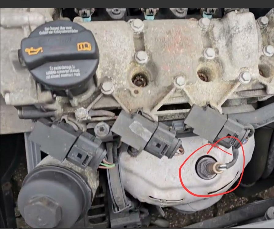
Your 'pressure difference sender' has part number 059 906 051C. Check search engine results for images thereof. Have been known to suffer heat damage. Fault codes would be helpful though. How many miles has it done, and what's the typical usage pattern (lots of short trips?).
-
Exhaust system will have a bit of a littering of sensors including about 3 temperature sensors, so I wouldn't be able to readily identify the one you are describing.
-
Skoda dealers have an RRP of £233 + VAT for the lambda sensor for your car (same part number as in LLL link) so you definitely don't want to be buying one of those from them without very strong evidence it is at fault! I've never heard of one being discussed in the context of DPF regen problems, to be honest. Will look up pressure sensor info later, just about to hit the road for a while. Try to grab some fault codes with VCDS.
-
I can find VIN from reg, so that's enough info. 👍
-
One differential pressure sensor only, I think, with one hose connection upstream of DPF, and with it's other connection downstream of DPF or left open to atmosphere (because exhaust pressure after DPF is naturally close to atmospheric). Sensor may be visible near top rear of engine bay if you can pop a photo up. The 'Fault codes' button when connected to control module 01 (engine ECU) should give you any stored codes. See first three images here: Guide: Check Your ECU/TCU Box Code & Software Version - Audi/Volkswagen Fault Codes button just under where it says Basic Functions in third image.
-
Could you please clarify the age of the car? You have CAYC as engine code in the thread title, but 2017 as the year in your profile, which would be a mk3 Fabia, and probably not a CAYC. Reg number or VIN would help me to offer definitive part number info for any given sensor.
-
Lambda and oxygen sensor are interchangeable names for something that measures oxygen content of the exhaust gas. This may be used to fine-tune the combusted mixture in a petrol engined car, or to help control various emissions after-treatment kit in a diesel engined one. Exactly how the lambda sensor in a CAYC is used isn't something I know. Differential pressure sensor is sensing the pressure difference upstream to downstream of the DPF. This can be used to infer the 'fullness' of the DPF. Genuine VW group sensors can be spectacularly expensive. Be happy that your car probably doesn't have NOx sensors, they would be a lot more. As for how to proceed; you say but is VCDS picking up any stored fault code numbers, and if so what are they?
-
Might be wires shorting at the cable entry of the thermoswitch connector, rather than one of the switches being welded shut. Which you've now disturbed and cleared the short? It is a horrible spot for access, and the connector latch is probably facing in an unhelpful direction. Last time I was in that area on a 9N3 Polo I used to own, the wiring just outside the thermoswitch connector was a right mess.
-
Good progress, try thermoswitch 3-pin connector out next, then reconnect 6-way.
-
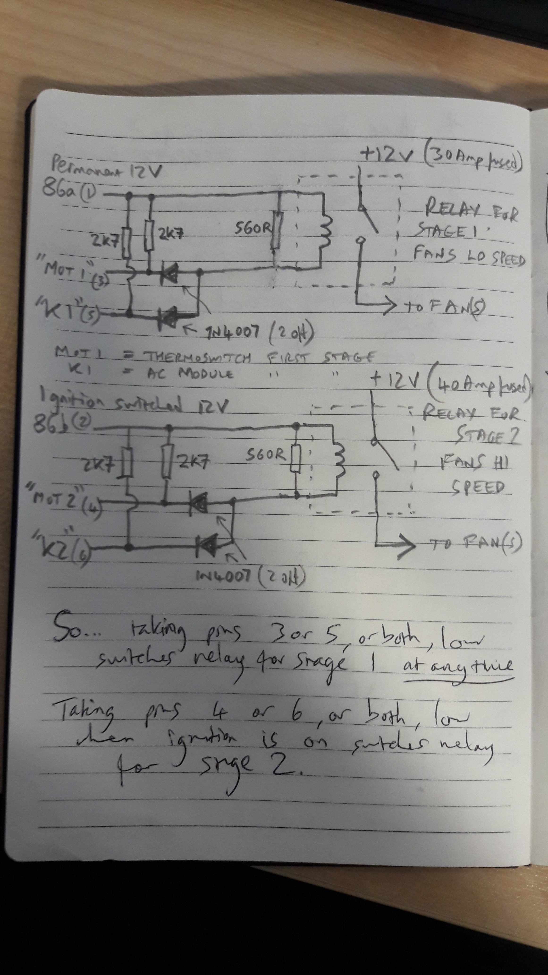
That schematic ^ doesn't include the 12V conns of the 6-way or the K1/K2 ones, let me find a page showing those, for completeness.
-
If the 6 pin connector was in, then if there was a trigger for the stage 1 relay, you should have measured the resulting short between 30b and 1, I would have thought. Yes, try 4-pin connector in, 6 pin out and see what happens. 86a is a fused permanent supply from one of the blade fuses in the battery fuseholder, 86b should only be 12V when ignition is on, MOT1 & 2 are from thermoswitch, K1 &2 from the HVAC control module in the cabin. No, thermoswitch is radiator mounted, 10-15cm above bottom hose connection.
-
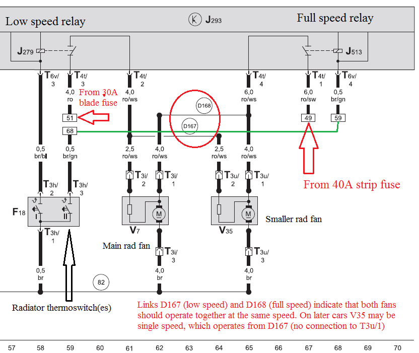
Could be the radiator thermoswitch stuck on? That pulls connection MOT1 down to earth I think. Could unplug the thermoswitch connector at the radiator and re-try. Would be unusual I think, because in cars with A/C that thermoswitch is only carrying relay coil currents, not the full fan power.
-
Only other scenario I can see resulting in fans on with ignition off is a short to earth on one or other of the wires connected to terminals MOT1 or K1, causing stage 1 relay to be energised when it shouldn't be. Was the 6-way connector plugged in, or not, when you were testing pin-to-pin of the 4-way plug on the FCM?
-
Access from below may be easier, not sure. Yes, 30a to 2 or 30b to 1 will be shorted, I think. May find that hitting the outside of the module unsticks it. On this scribbly circuit of the internals of the FCM, the connections on the right of the sketch are 30b, 1, 30a and 2 reading from top to bottom, I think, looking at the terminal sizes on the side of the relay module.
-
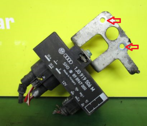
It won't be anything to do with the thermostat, I don't think. Probably a stuck relay within the fan control module, which hangs off a bracket on nearside chassis leg near bottom hose radiator connection. Edit: looks like this
-
If the facelift happened at a change of Model Year, then the tenth charchter of the VIN should tell you.
-
Oil in coolant generally means oil cooler failure.
-
Look at the car instead of the internet until you've found the sensor and examined the cable, and the inline connection where it meets the engine bay loom. Until you've looked for any possible wiring damage, it's not really possible to know what may be required.
-
See if the wiring looks OK first. The fault code is for the heater part of the sensor, which cleaning will not help.
-
@Jocko, yes I expect that's the difference.
-
Firstly I think there's only one lambda/oxygen sensor. Are you used to petrol engines? Here's a webpage showing the two different options for LHD (L0L) and RHD (L0R), as the last two item 1 part numbers. Car Parts Catalog - LLLParts What makes you thing it has a problem?
-
Read this: Energy management.pdf