




Breezy_Pete
Sponsor
-
Joined
-
Last visited
Everything posted by Breezy_Pete
-
Oil level sensor and QI6 servicing code at delivery both confirmed.
-
I think they stopped supplying stickers with car details about 5 or 6 years back. Will read/reply to your message shortly. Just sat down to eat.
-
Sounds like a good plan to me if you have the money to do the lot in one go. Get a friend to follow you before and after the job to see if there's a noticeable drop in tailpipe smoke. Although I guess if it's running on three just now, it's probably not going to be a fair comparison!
-
In my post about oil level/temperature sensor I did offer to look up whether you had it if you weren't sure. I still can, via reg plate or VIN, but I think Ootohere is probably correct that it will have.
-
-
Perhaps they've gone back to it with the Scala?
-
Do you know if the car has an oil level/temperature sensor in the sump? If that's not there, I think you wouldn't be able to set it to variable. I could check with VIN or reg plate number if you're not sure.
-
https://www.ebay.co.uk/itm/316063424221 There's another one, from Lithuania, but it looks pretty grubby/rough all over.
-
03F 133 062 is what is listed for your car, and it has not been superseded by any other part number. Skoda want £477 + VAT!! A quick look on ebay suggests you could get a secondhand 03F 133 062 for £50, which might be worth the gamble. I don't see posts about failures very often at all on here, so I think they're generally pretty reliable, therefore used ones may well be fine. In the case of this part, I wonder if the different suffix letters might indicate different diameters, for different engine sizes? Just a guess. Worth a good look at the wiring near it first though, in case there's some obvious damage/corrosion of connector contacts etc.
-
Did the replacement pedal get tried? Will look up about TB in a few minutes.
-
If you let me know the reg plate number or VIN I can look up the current part number suggested. Different suffixes can indicate quite different, incompatible parts sometimes. Have you read 03F133062 off the existing TB?
-
It's actually normal for the door looms to have splices where single brown earth wires split off to two or three places, it may be that you're looking at this, with some more recent tape added. Check that the motor currently fitted to driver's door is 6Y2959802, and also says SK240DDRS on the same label. Passenger side motor is a slave to the driver's side master unit, so won't work more than briefly until it's got a working driver's side one. I can repair the drivers side module, if it's the correct part. Message me for details if you like.
-
Is it both windows that are working for a while then stop? If so that's usually a sign of a failing driver's side module.
-
Well done, and thanks for coming back to let us know what fixed it. 👍
-
Oh, even better then. Take the front right off out of the way.
-
Hinging front open round the aircon pipes will make everything easier, I think, but haven't tried without. Pretty quick and easy to open up the front.
-
See last bullet point of first post.
-
Ta; but this engine is longitudinally mounted, so I guess I'd have to be listening somewhere under the gearstick instead.
-
I've no idea what it's doing. New experience for me having one.Yes.Yes and yes. Colours going to sensor 2 ( bank 1 sensor 2) are: From fuse to sensor pin 1 - blue/yellow From ECU pin 5 to sensor pin 2 black (thicker one) From ECU pin 35 to sensor pin 3 green From ECU pin 16 to sensor pin 4 black (thinner one) Connections 1 and 2 at the sensor are the heater.The second (nearer tailpipe) sensor should only have 4 wires, maybe you are looking at that? The diagram I posted is for the one nearest the engine, which is a wideband type, these always have more than four wires, I believe.It's this I think:
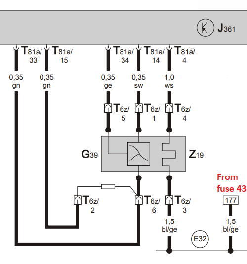 @Treb_Kavon can you please share the VIN, so I can pick the most relevant diagram by build date?



Important Information
Welcome to BRISKODA. Please note the following important links Terms of Use. We have a comprehensive Privacy Policy. We have placed cookies on your device to help make this website better. You can adjust your cookie settings, otherwise we'll assume you're okay to continue.