
Breezy_Pete
Sponsor
-
Joined
-
Last visited
Everything posted by Breezy_Pete
-
Ah; Anti-Roll Bar drop links. Very common problem.
-
Not sure what a L+R linkage is.
-
Doesn't that take quite a lot of current @J.R.? Have you measured how much?
-
Oh, OK; so it might be that the switch was good but the oil pressure wasn't.
-
In what way did the old switch fail? False alarm? No alarm when there should have been? Or leakage?
-
The pressure switch is M10 thread, 1mm pitch if that helps. https://skoda.7zap.com/en/cz/fabia/fab/2005-453/9/919-919040/ Why not just fit a new genuine switch and forget about it? The first one lasted 14 years?
-
Another avenue you could explore @RicardoM is to disconnect the LIN connection to the alternator. That will surely log a fault code, but I'm not sure if it will put any warning lights on. According to that energy management document referred to earlier, "The alternator on a model with an energy management system comes fitted with a LIN regulator. These alternators have two terminals: the bolted B+ terminal, as well as a double connector in which only pin 1 is assigned to the LIN line, and pin 2 remains unassigned. The data bus diagnostic interface J533 sends LIN messages to the LIN regulator. Depending on the status of the onboard power supply, these LIN messages specify voltage values of between 12.2 volts and 15 volts, which the regulator then sets. If these voltage values are not set, e.g. because of a broken LIN line, the regulator detects this and sets a constant alternator voltage of 14.3 volts on expiration of a pre-defined interval." That sounds like it defaulting to 'traditional' alternator behaviour which may suit you better. Experiment. Lots of people report disconnecting the LIN wire at the battery management shunt module and getting the same result, which seems reasonable. Scaremongers will possibly tell you that this will over or undercharge your battery, and all sorts of disasters will happen, but I suspect that it will just work more like you want it to. It would be interesting to get some good data on this from a man of your scientific, methodical nature.
-
Consider fitting an LCD voltmeter module somewhere where you will be able to see it from outside the car. I found an 'unwanted' one at work that has an operating current of only 350uA. It needed a 5V regulated supply for which I added an efficient regulator. The total addition to the car's quiescent current is just 0.5mA. Obviously at that power level it isn't backlit, but phone (or other) torch can help if you want to read it in the dark before opening the car.
-
I have an old master cylinder I don't mind taking a hacksaw to, if that might be useful?
-
@Hayley294, what were the figures for each cylinder? I think Ricardo's suggestion is sensible, knowing these engines.
-
50mm sounds good. I doubt it matters much where you earth it to as long as the wire from the negative terminal is thick and well connected to the bodywork.
-
Go here and download the bottom file in the list "Inspection and maintenance"
-
Much appreciated, and good pics. Those hooky/barby bits are subtle details.
-
Wiring between body and doors seems a common problem area on the mk2s, but not a particularly serious one. Keep your oil and filters fresh and all should be well.
-
Probably also because the assessment of state of charge is approximate rather than exact, and if it were set to 100% it could result in overcharge/damage, and waste of energy. Edit: Possibly also because when put in for emissions test cycle analysis during EU type testing the cars are allowed to start the tests with battery fully charged (I seem to remember). This would result in the possibility that during test cycle the battery management could operate its normal software whilst also never or barely having to load the alternator, as it could decline to 80% charge before any charging was invoked... Jus' wondrin'...
-
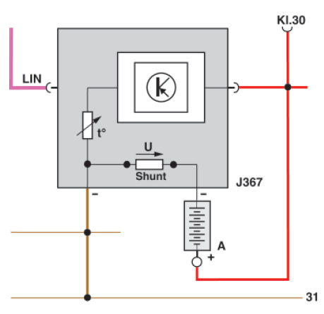
The "Energy Management" chapter within the document here is useful https://www.scribd.com/document/410157436/SSP-477-Audi-A1-pdf Snapshot of key diagram:
-
OK, well that's the current that the battery management module shunt is telling the car/VCDS about. If there's a current flowing from the battery negative post through the shunt to chassis, then that is the battery charging current (generator current minus consumers current >0). If there's a current in the other direction through the shunt, from chassis to battery negative, then power usage exceeds generation by the alternator. When the two currents balance perfectly - alternator matching demand - there will be zero volts across shunt, no flow into or out of the battery. Unless I'm going mad...
-
Good work!
-
Wiring diagram suggests a microswitch associated with the Rear lid central locking motor. Shown as normally open (tailgate closed, I guess), grounding the connected wire when contact closed (tailgate open?). Wire is white emerging from the motor module, turning to brown/blue at pin 3 of a 5-way connector on left side of luggage compartment. Find that connector, measure what's going on, add extra manual switch over-ride, I guess?
-
Could you clarify your question a bit please Ricardo? Do you want to know the output current of the alternator at any given moment, or the actual net charging current into the battery (alternator output minus connected loads consumption)? Or do you mainly want to understand how the alternator is controlled to achieve the required outputs?
-
In the earlier version of circuit diagrams, fuse 24 is shown as 10A and described as "Central locking motor in rear lid". So that looks relevant.
-
Reckon you could do some measuring and sketching of yours? Looks like a fun thing to try to make.
-
I'd be interested in seeing your connector latch tool. No idea on pulley bolt torque, just go by feel.
-
You just lever the dust covers out with something like a pick tool. They soon give up and move, you won't cause any significant damage to them. I suppose VAG thought that the plastic of the radiator end-housing would function adequately as a sealing washer, as there's effectively an annulus of it between the brass threaded insert inside, and the face of the thermoswitch, from what I can remember. To be fair, they do seem to go a dozen years or more before they start to leak. I guess the plastic just 'does plasticity' very, very gradually over the years and temperature cycles. Retightening seems to work. Just be careful not to break the latch of the connector when removing it. If you're new to these types, watch a youtube video on the subject first.
-
Yes, 35Nm sounds right for the thermoswitch. Don't bother taking it out, just tighten it. For the tensioner pulley, just take the pulley off, leaving the tensioner in situ, pull back the plastic covers on both sides of the bearing and re-grease. If it doesn't seem to undo in the conventional 'lefty-loosey' style, try the other way. Can't remember for sure but I think it might be conventional on a BBZ.