
Breezy_Pete
Sponsor
-
Joined
-
Last visited
Everything posted by Breezy_Pete
-
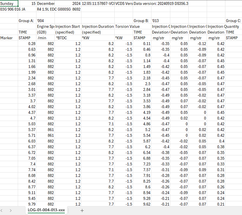
The log has a couple of minutes more data, including a few blips of the throttle, which as per a youtube video I watched first, briefly reduces the torsion value to -1.0 each blip. Not much else seemed to vary.
-
Thanks mainly to @Golf-Fiend and @SuperbTWM in another thread that has become a bit polluted; I've just grabbed some data that appears to show an issue with the timing, not sure how bad, but probably worth tweaking. Injector deviations also logged briefly, at or near idle, with warmish but <50°C engine. I'm not sure what engine temps are best for logging either torsion value or deviations. Anyone know if that -1.5 needs a clockwise or anticlockwise turn of the cam to reduce towards zero, please?
-
We being who? Many rainforests round your 'neck of the woods'? How much pressure do you think you can put on countries with significant amounts of rainforest, realistically? It's sweet that you think they just haven't realised, and now you've told them what to do all will be well.
-
How?
-
The problem with Ken's chemistry is that he neglects to mention that the oxygen comes mixed with rather a lot of nitrogen.
-
-
-
No, just one that looks at intake cam. Link in my previous post shows enough about checking timing, I hope, though you might need to read a bit as well as look at the pics. You don't need timing tools to check, just eyeballs.
-
My first thread about it needs the pics rescuing cos photobucket stole them, but this one will probably give you enough idea: https://www.briskoda.net/forums/topic/507743-low-power-sluggish/#comment-5701026
-
Oh, in that case I do know how to check the chain timing, but just visiting someone so won't be able to do much for an hour or two. I've posted the relevant photos several times so searching the mk1 Fabia forum may get you there.
-
Previous owner said he'd replaced all glowplugs yes. I should probably check them anyway. Yes, smoky start up. Will try to check torsion business tomorrow. Thanks. Edit, just arrived after a 3.5 hour cross country trek with it, and the journey average mpg was 53 ish, so there's probably not too much wrong. Want more to make it viable though. Going back to my Polo is seeming pretty tempting just now.
-
I'm away from resources for a few hours, but off the top of my head, I'd expect the 3 wires at the cam sensor connector to be Earth, +5V and signal output. The 5V will only be present with ignition switched on, possibly ony with engine running, try both. Earths are typically brown or brown with another trace colour. Tell us what colours you have at the connector. Not sure what you'll measure on the signal output wire, but verifying the 5V and earth is a good start. Maybe look for YouTube videos or Google results for checking chain timing on the 6-valve HTP engines too.
-
@SuperbTWM I did log deviations yesterday on my morning commute, start and end of anyway. Was wondering the same, how does the ECU know what's actually been injected each time, as opposed to what should have been? Busy today, but might get a chance to pop a graph to tomorrow. There were some deviations beyond ÷/-1, but only when driving, and only early in journey (2 or 3 minutes in, up a sheepish hill), not when just idling. It does also start poorly when warm, and also after a few days of non-usage, so leaking may be going on. @Graham Butcher NOx isn't measured at MOT in the UK. On diesels, opacity/smoke is the only thing measured.
-
Timing chain jumps are also possible on the HTP engines, both types. Can result in cam sensor fault codes, not sure about misfires. If it is still misfiring, there ought to be a fault code for that too? Maybe just running very badly rather than misfiring as such? That might point toward chain jump too.
-
I wouldn't want to try oils on plastic, might make them swell up and get tighter.
-
That code is for camshaft, not crankshaft sensor problem. I guess that's what you actually changed? On top of rocker cover, rather than down the back of engine block? Yes, wiring fault is very possible. On the back of the car, where it says HTP, are all the letters black? If so that's the single cam engine. Twin cam HTPs have a red P.
-
Is this the 54 bhp, single cam version of 1.2 HTP? If so I would always recommend a compression test if misfires occur despite new plugs and coilpacks. What fault code number is the crankshaft code?
-
Pop a photo of your engine up, minus any removable top cover.
-
Yes, breakers are probably your best bet. Autodoc etc will probably only have LHD versions. Some sellers may not realise there's a difference. Part number for LHD probably starts 6Q1 instead of 6Q2. Possible that you could adapt one of those by lengthening the cable IFF that's the only difference. Might be that the sensor end is handed though.
-
-
I think there's a little dipstick built into the cap, but it's lots of years since I last looked. I remember ours being very resistant to being unscrewed the first time I tried, probably hadn't moved since it left the factory a decade or more before when I tried. Access was awkward to get a good grip though.
-
Buy one with the correct connector already on it. Part number to match is probably stamped on the existing one.
-
Might just be an indication of a weak battery, do you know how old it is? Fluid doesn't degrade in these really.
-
Very helpful, much appreciated. Will have a go tomorrow.
-
@Golf-Fiend thanks for this. Would you have any guidance on which measuring block groups need viewing/logging, and under what conditions, please? I have VCDS, but no idea what to look for. Is it just a case of finding one where individual injectors are shown with some number and see how similar those numbers are?