Breezy_Pete
Sponsor
-
Joined
-
Last visited
Everything posted by Breezy_Pete
-
-
It'll still work like that, because that is all there is to it. Just needs to be located somewhere so it doesn't bounce around.
-
Outside temperature sensor. Should be a hole somewhere within reach of that wiring, for it to clip into.
-
-
Sounds like you've done OK with it @CReese123, try not to worry. On both mk1 Fabia and Roomster with these same M8x48 screws, the official erWin info suggests 20Nm + 180 degree turn, which needs a decent effort and feels a bit scary. Unfortunately I don't have the erWin stuff for mk3 Fabia. Making certain the tool tip is fully (and square on) engaged in the screw heads is very important to reduce chances of slipping and rounding off. Tapping end of bit with a hammer is useful to ensure such engagement. A special tool of this style is very handy, particularly for the offside: https://www.ebay.co.uk/itm/314719915154
-
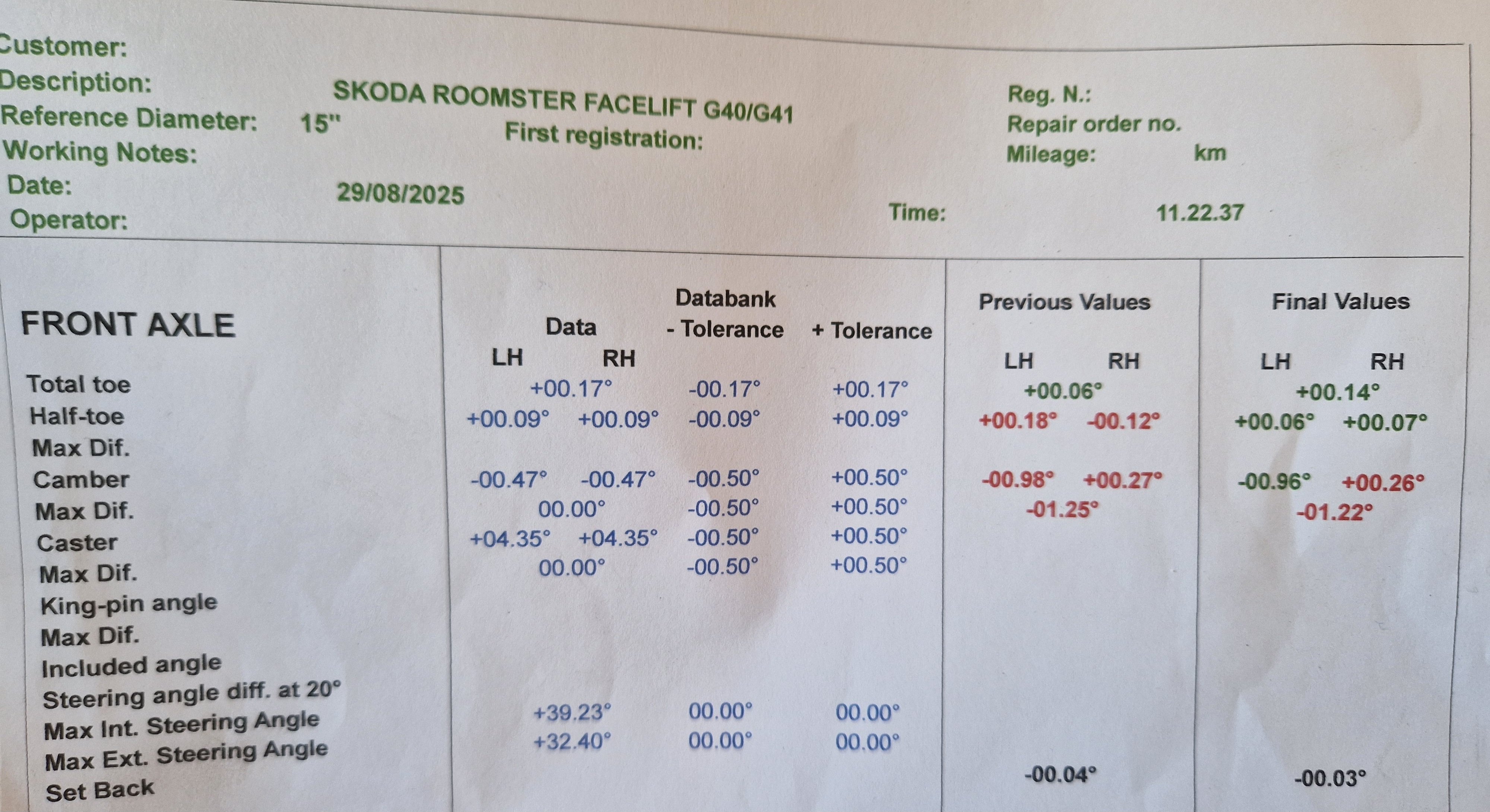
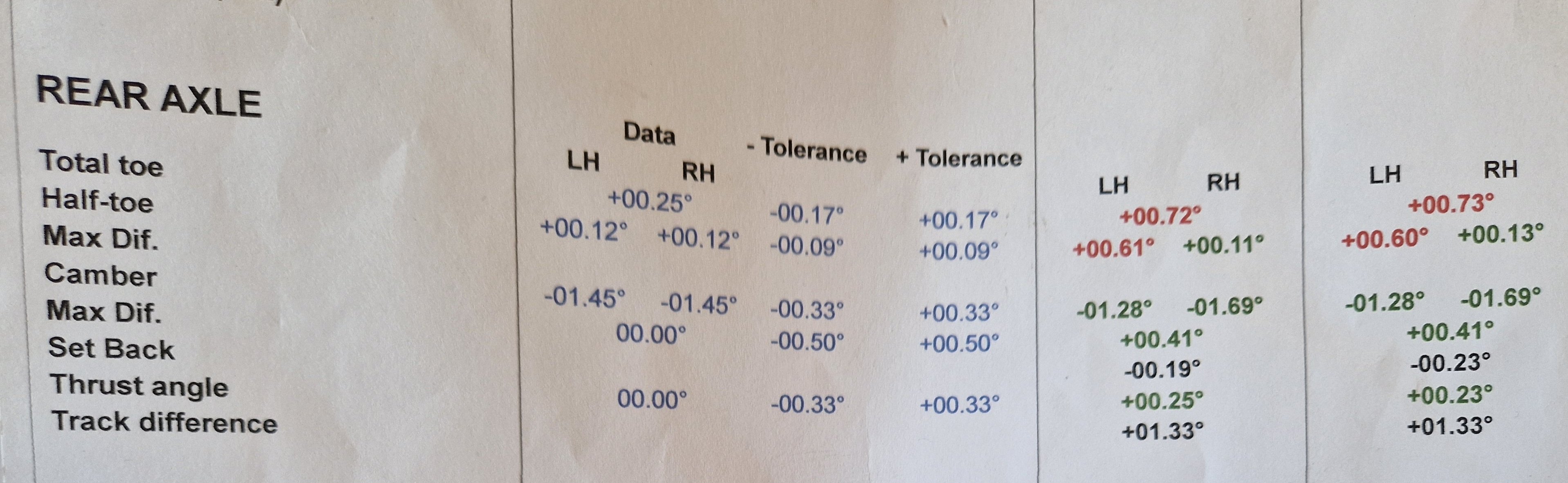
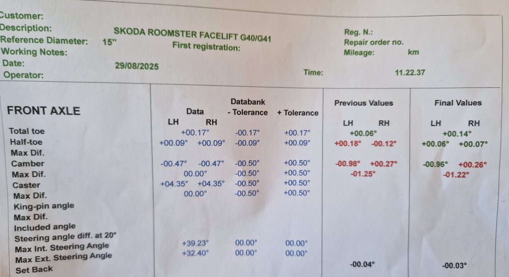
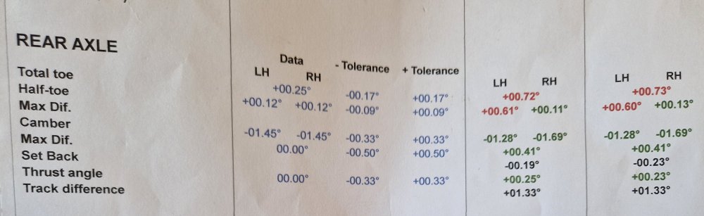
Alignment tweaked Front toe now looking a lot better, but camber a bit asymmetrical. Something bad going on at rear left, wonder what I can do about that. Pretty sure there's no official adjustment there.
-
Now has a PASS. 😀 Currently on the ramps at the local tyre place getting alignment checked, as there were some inner shoulder tyre advisories. Sawtoothing at the rear, I think, and just inner shoulder wear at front. Looks like they're adjusting toe settings, oxy torch waving about.
-
-
Broken (blue) exciter wire will be obvious by the battery symbol not appearing on the instrument cluster when ignition is turned on to the point lots of warning lights self-test. If broken it might cause charging issues, but unless this causes a flat battery, will not have any impact on engine start. @Alasdair1 you might be thinking of the starter solenoid wire instead? When that breaks it causes a no-crank non-starting situation? This engine appears to be cranking OK. Unfortunately you are too far away for me to help in person. It has got petrol in the tank, right?
-
-
For the VIN you supplied, I'm only finding one temperature sender listed, part number 04E919501B, superseded by 04L919501. No other search results come up when I use search terms 'temperature sensor' (instead of sender") with any relevance to the coolant system. Nor for "radiator outlet". I think I would conclude that G83 isn't fitted on this car. I'll have a quick double-check by consulting wiring diagrams.
-
-
Good idea, may well have been.
-
New bearing's on, retest booked for Friday at 08:30. Didn't even get rained on! 🙂
-
Close but no cigar, as they say. Both headlights aim too low and too far to the right; which is a bit odd. They'll adjust those prior to retest. OSR wheel bearing rough. Bought a spare for the wheel bearing a while back, but was in one of those quandries "is the noise definitely coming from the right?" Neither of us could tell for sure from sitting in the back seat while being driven. Wish I'd done a bit more investigation, with hindsight. Will get into that this afternoon, in the first rain for ages...😆 Could have been a lot worse, I think.
-
I'd be happy to have a look at the circuitboard for you sometime, although I have a bit of an aversion to removing and replacing the needles of the various dials. Whereabouts in Oxon are you?
-
Thanks Lee, much appreciated.
-
Fingers crossed please friends. Dropped off the Rescue Roomster at a garage round the corner just now. MOT not due until December 24th (how did that come about?), but wanted to bring it forward to a more conducive time for working on cars. Replaced the flexi on the exhaust yesterday, and changed one slightly whitish indicator bulb, but other than those, didn't spot any obvious fails. We shall see. There's a small pit/crack in the front windscreen, but near the middle, below the rear view mirror, so I think it'll be OK. Don't think it has been an advisory previously.
-
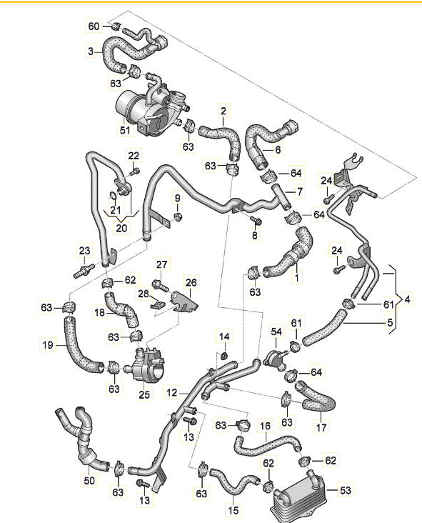
Item 20 is 04L121065AJ (RRP £44.90 + VAT) as shown here, along with part numbers for a lot of the other bits you mention. Car Parts Catalog - LLLParts It appears to be this bit: Its o-ring, where it connects to the engine block is correctly given as item 21 on that page (over £6 at dealers!) That LLLparts page isn't up to date enough to feature the suffix -CR part for item 7 (also @ RRP £44.90 + VAT currently), as mentioned in my post yesterday. Note: although very conveniently selling genuine parts at good prices, LLL can be rather slow to deliver. Think weeks rather than days. Dealer ought to be quicker but will obviously charge full RRP. I would speculate that you will find it awkward (and expensive!) enough to replace these two, along with directly attached hardware, to want to do any other replacements.
-
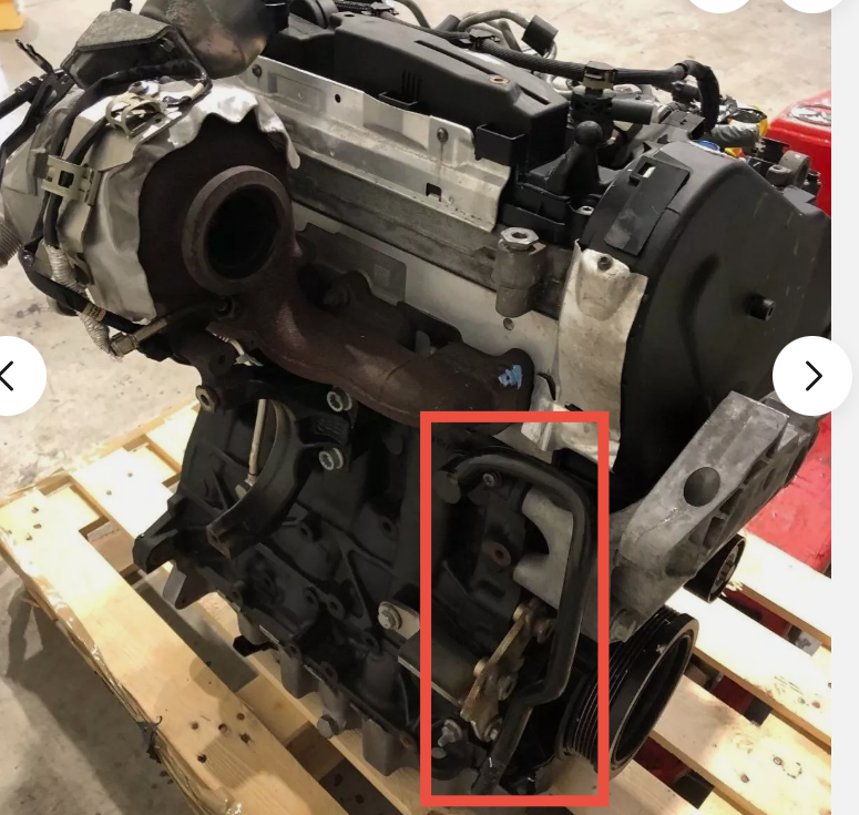
I'm going to need more help. It's not clear where on the engine those are, the picture is a bit too close in for spatial context. Do those two appear recognisably (to you) in this image? The title of this page in ETKA is Coolant cooling system D - 26.05.2014>> 2.0 Ltr. rear Diesel eng.+ PR:DN1,DN4, DN6,DK7+ There are at least two other diagrams though, titled right and left side. The part numbers you quote in your post, without suffices are items 12 with suffix AF, and item 7 with suffix BH, superseded by 04L 121 065 CR , for your VIN. Those two don't appear to be adjacent in the exploded view, so I'm confused about why you think those two base numbers are the ones in your pic?
-
Be careful, the suffix -A appears to be a different part, listed for other Skodas. May not be correct thread or whatever. See results here for search on the part number without suffix: https://www.skoda-parts.com/spare-parts/8K0805615.html
-
Damage or just wear? Pics of the bits or old strainer? They can go a lot further than yours has on original chain/tensioner/guides.
-
6Q0711051, not 600... Any scrapyard should have one in usable condition, I would think.
-
Why? Is the oil pressure OK now?
-
The timing chain won't have broken, but it may have jumped a tooth or two on one of the sprockets. Cam sensor error can be generated by this. There is a fairly straightforward way of checking the cam to cam timing, involving removal of some covers at the gearbox end of the rocker cover.