Everything posted by Breezy_Pete
-
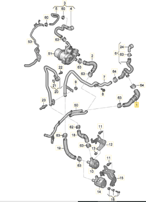
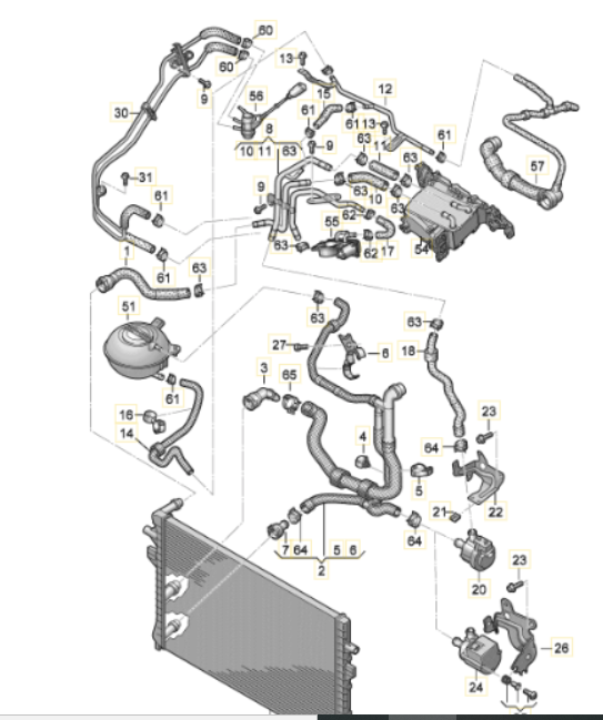
It could also be one of these, which are described as the 'rear' set of coolant hoses, but I think your photo is the front of the engine; though I guess that may be coming round from the back.
-
The relevant diagram is supposedly this one, which should be able to be made bigger by clicking on it. Struggling to pick which of the vast array of hoses is the one in your photo to be honest. If you can tell me which item number you think it is, I'll gladly supply you with part number. Sometimes these diagrams are over-generalised and don't correspond 1:1 with the reality seen under the bonnet...
-
Another footpumper here. 👍 Plus a calibrated (when new) gauge.
-
erWin Skoda will have the info in maintenance manuals for any given Skoda but these will be engine-specific, so not easy to generalise. You can download info from there for a small fee.
-
What year is the car?
-
I guess the original o-ring may have lost it's springiness, and failed to seal well onto the new breather module. Do you want/need/have the part number of the hose? I would imagine a fresh o-ring of appropriate size will do the trick though?
-
All the best dude. 😁
-
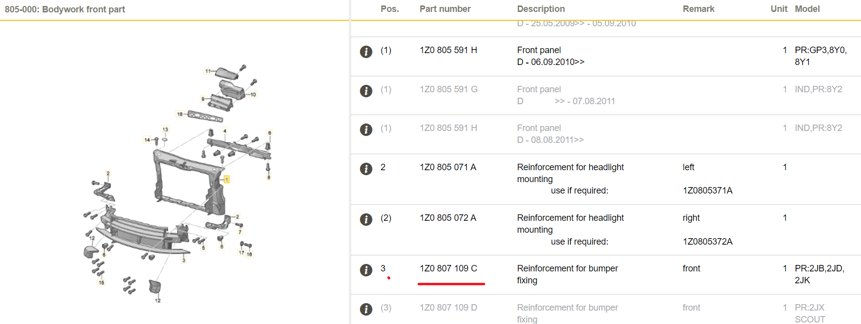
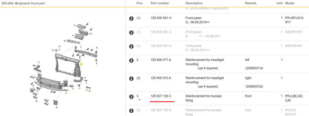
Morning, As expected your VIN gives the suffix C part as correct for your car; feel free to ask if there's any further bits you need to research:
-
According to the grey equivalent parts section near the top of this page, the suffix Q should be compatible with all previous revisions, maybe they sent the wrong thing? Does it look like the image here? Connecton pipe Škoda 06L115678Q (skoda-parts.com) According to parts catalogue, your car should have been built with the suffix C version, but it also says: "Dropped: 1 Nov 2016 (EKZ: M) Please contact your dealer for the parts interpretation." So you might have to do just that. (unless you can find a suffix C or D or Q part that looks right for sale anywhere in UK)
-
This is interesting and correlates with something mentioned on here about a Skoda Dealership saying the same, see post by andymod: https://www.briskoda.net/forums/topic/52122-timing-belt-change-interval/page/4/#elControls_5769794_menu
-
This is probably your best bet https://www.lllparts.co.uk/catalogs/skoda/CZ
-
@Steroidas does your engine coolant ever get hot enough to trigger fan activity when clima is off? If so, do both fans spin up together in those conditions?
-
Broken wires on the way to N280 is certainly one possible failure that might explain your troubles.
-
You won't find a clutch on your compressor either. Proportional solenoid valve N280 varies the displacement of the pump, axle is always spinning.
-
What device has generated those fault codes? I suspect it is not giving good information. No F129 in any Roomster circuit as far as I can see, therefore it doesn't exist, G65 is doing that job instead (and better).
-
27 pages of discussion on it here, I think
-
Unfortunately, you are going to have to physically look at the existing fan to fully identify it. Your VIN gives two options, which are probably not interchangeable. If the current AC system is by Valeo, the fan will have part number 5Q1819021B, which has been superseded by 5Q1819021H. If it is a Denso system it will have fan part number 5Q1819021A, superseded by 5Q1819021J. You need to know which of these you have. Both ETKA pages have this in the title: "Before parts order, physical inspection of old part necessary"
-
If you tell me the VIN number of the car I can tell you the correct genuine part number, that may help.
-
There may well be a relay involved, which possibly has slightly worn contacts; that might explain intermittent function, maybe.
-
Looks like there's a gap in the erWin Skoda circuit diagram coverage of Citigo. Document I have (where it's fuse 36) only goes up to late 2015, the only other one on there seems to be 2019 onwards. Odd.
-
All's well that ends well. Yep, Citigo is a rare exception to the 'permanently live ciggy socket' situation on most VW group cars
-
-
Hmm, diagram I'm looking at may be wrong one, what does your fusebox look like?
-
Should be 2nd one from left, bottom row?
-
Oh, OK, if you're sure you've got the numbering right. LHD/RHD confusion often arises from single diagrams in Owner's Manual?