Breezy_Pete
Sponsor
-
Joined
-
Last visited
Everything posted by Breezy_Pete
-
I don't think it matters what order you undo the fasteners, but definitely have some assistants to stabilise it once the hinge is removed, while you focus on fitting the new one.
-
Where did you take it for the MOT? Seems no harm in naming and shaming if you don't plan to try to get them to rectify anything?
-
Rather common actually. Often just half a coil or less at the bottom, or most commonly at the top, I think. Fractured means broken anyway. But I'm right with you on the struts being cocked up.
-
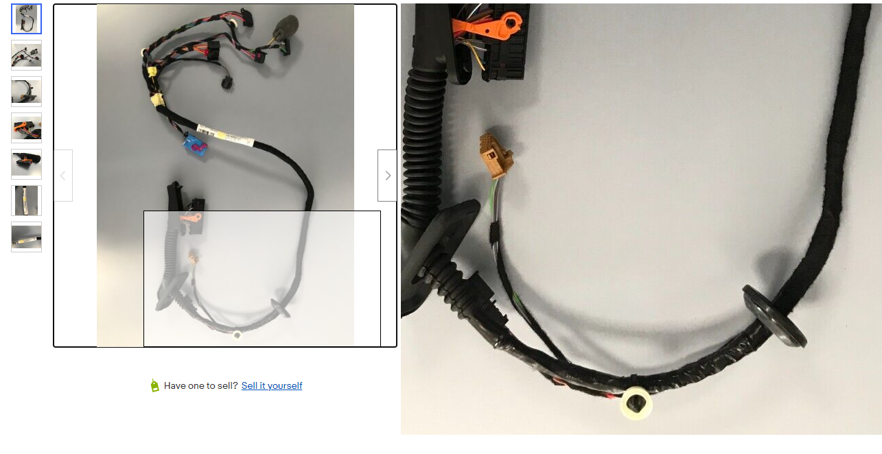
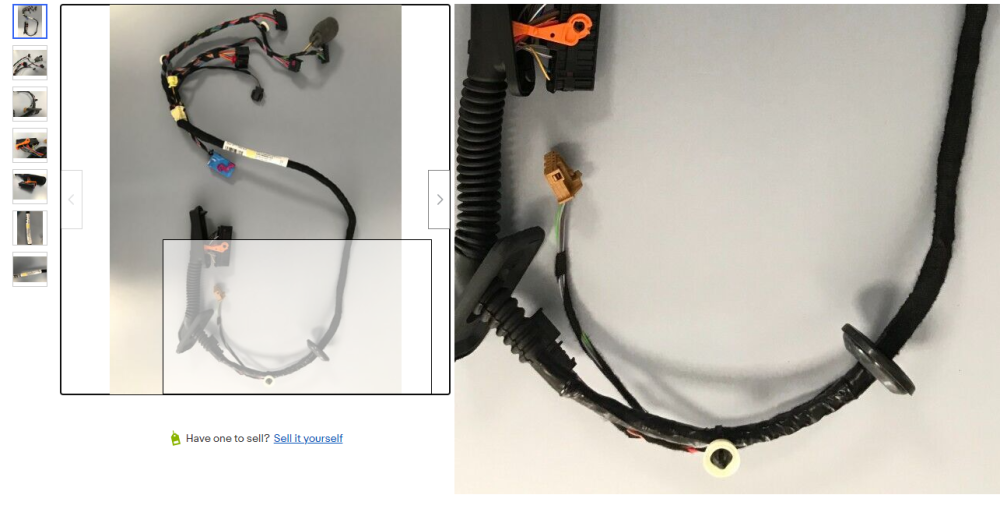
OK, no need to shout. Did you get any pics? Some Skoda looms can feature a lot of what just looks like standard black insulation tape e.g. from an ebay listing picked just now:
-
OK, fair enough, just be aware that there's likely to a raised area of corrosion all around where the lower washer of the banjo bolt sits on the caliper. If removed and replaced straddling any of this raised area, tha washer will struggle to seal.
-
With the brake hose, you may be able to detach the caliper and send it round, to avoid opening the hydraulics, not sure.
-
I expect they bent/brutalised that tab to get the bolt through it. Don't despair, just fix each issue one by one. 🙂
-
The tape may well have been original. Well done for fixing. Had a look at other side yet?
-
Match the 6q0909606 and fit. Job done.
-
I'm sure you're right. What shocking workmanship. ☹️
-
Video is v. helpful. 🙂 Footwell wetness and corrosion/shorting local to the sensor seems much more probable than condensation getting to airbag ECU area, I think.
-
Yellow wire on pin 1 from pin 70 of airbag ECU conn, black wire on pin 2 merges with various other earths behind dashboard allegedly.
-
What year is the car?
-
Wiring isn't shown as going through the door connectors, so definitely in the main bit of cabin somewhere. @varooom would be my goto guy for this type of research.
-
Wiring diagrams show G179 as external to the airbag ECU, but unhelpfully don't give any clue about location. Has a two-pin connector.
-
-
There's a similar story on here somewhere where the OP got an independent auto engineer/inspector involved, who was able to demonstrate that Skoda's diagnosis was nothing better than a guess. When further disassembly/inspection occurred it was shown to be plain wrong, and a faulty from manufacture clutch was shown as the most likely cause. That's all from memory, I'll try to find the thread for you tomorrow if no-one else does first.
-
.
-
I don't know much about crankshafts, which image has five main bearings?
-
Could also be AH. I just can't see dots where dots should be to make that last letter read as an M?
-
Click on the various engines here for comparisons of bore size etc. Specs for all Skoda Fabia I versions (ultimatespecs.com)
-
You'd definitely not want that one if it is really an -AN, that could be quite different.
-
To my eyes the last letter of the part number engraving might be an N rather than an M though? AUDI A3 VW GOLF PASSAT 1.6 TDI INLET INTAKE MANIFOLD COOLER 04L129766AM | eBay ?
-
If the part number is the same, it's the same irrespective of brand.
-
Yes, thank you @varooom. I was able to confirm using OEMwolf.com that B>N, N>Q, H>Q, and strangely unalphabetically S>Q (where '>' is intended to mean was replaced by). But that site isn't up to date enough to cope beyond Q.