Breezy_Pete
Sponsor
-
Joined
-
Last visited
Everything posted by Breezy_Pete
-
That could be physical damage to the loudspeaker cone. Take the door card off and have a look.
-
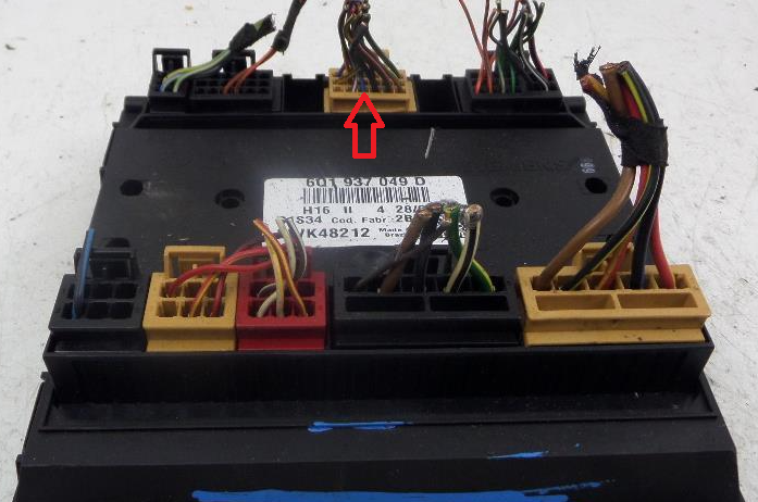
This image is inverted compared to when it is mounted in the car. The red arrow is not relevant here.
-
Evaporator
-
All it does it cool the air, that's how it removes the moisture, by condensation. What else do you think it does to the air that might constitute 'conditioning'? The guff about seals drying out if not used constantly is also way out of date, with modern clutchless systems circulating some refrigerant all the time, even when the system is off.
-
Why another thread? https://www.briskoda.net/forums/topic/487004-v-power/
-
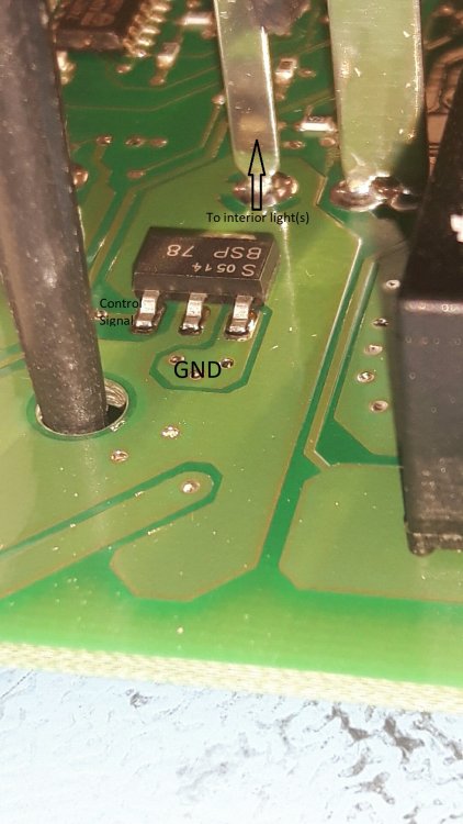
The interior light 'controlled ground' connection is done by this device, I've just seen: Datasheet here: http://www.farnell.com/datasheets/1651292.pdf Can be just on/off in terms of grounding the low side of the lights, and/or can do fancy stuff like fading out gradually.
-
Just confirm for me that you've checked fuse 11?
-
In that case definitely talk to Mike. With your registration number he'll be able to look up what is exactly the right part number for your car.
-
Not pistons, exhaust valves, on the HTP engines. The 6-valve engines seem more vulnerable, Hold out for a 1.4 like yours.
-
I assumed that you read the part number off your existing loom, therefore it has to be correct. I think it's a case of the loom is for driver's side, which will be left in countries where they drive on t'other side of the road, like where those links go. The part number you quoted appears (8th one down) amongst a bewildering array here: https://skoda.7zap.com/en/cz/fabia/fab/2008-608/9/971-972035/ No mention of left or right, just driver's side. Do give Mike at Coverdale a ring, you might find he can do you a better price than anything else I've suggested. I'd be interested in buying your old loom off you for a small sum, to investigate what's failed and why. PM me if interested, once you've got the replacement in and everything working.
-
Sounds like you want to put something like this on your Christmas wishlist: https://www.amazon.co.uk/Sealey-AK7301-450mm-Breaker-Silver/dp/B000WZABDO/ref=sr_1_6?dchild=1&keywords=breaker+bar&qid=1605464757&sr=8-6
-
Yeah, both of those seem OTT. Try Mike?
-
One here from Germany; they're a hell of a price, are you not tempted to just repair the existing? https://www.ebay.co.uk/i/113912711086?chn=ps&norover=1&mkevt=1&mkrid=710-134428-41853-0&mkcid=2&itemid=113912711086&targetid=1000771055974&device=c&mktype=pla&googleloc=9046125&poi=&campaignid=10204071489&mkgroupid=107296306292&rlsatarget=aud-381667280803:pla-1000771055974&abcId=1145987&merchantid=6995734&gclid=EAIaIQobChMIkdyg9IKF7QIVkbh3Ch2vxA6TEAQYASABEgJAlfD_BwE Better price here, depending on postage https://www.skoda-parts.com/spare-part/5j0971120bl-front-left-door-electrical-wiring-installation-bundle-skoda-21827.html
-
Yep, if it says FTDI, and stuff about K-line or KKL, it can probably work. Download the VCDS Lite software directly from ross-tech though, there are suggestions that ones that come with cables on CDs etc. might have 'bonus' malware.
-
The registered version of VCDS Lite does everything I've ever wanted or needed to do on mk1 Fabia. Third-party cable for less than 20GBP, like this: https://www.gendan.co.uk/product_VAGUSB.html or similar can be found cheaper on ebay. VCDS Lite is freeware. If you find it can't do what you want, register it for 99USD and then it probably will. Function chart here: http://wiki.ross-tech.com/wiki/index.php/Functions#:~:text=Function Chart VAS%2FODIS VCDS-Lite, Yes 35 more rows
-
I don't think so. Checking the suffix -AL part number on a site where I routinely check for supersedences doesn't suggest that it has been superseded by any other number. So that and the -BL part are different in some way. https://oemwolf.com/oem-parts/5j0971120al.html
-
Really need to somehow see whether the button signal is being received by the Central convenience unit (module 46). Not sure what measuring blocks there are, but I expect there must be a relevant one?
-
Was the key very cheap?
-
If you have VCDS you can look in Measuring Blocks of Central Electronics what status J519 thinks each door has (open/closed). If you don't, then disconnecting each door, one by one, should tell you if there is a door giving a false indication of 'open'. The connectors involved are as I described before. 6 way brown ones at front doors, blue at rears.
-
When the door is closed, the switch does not conduct (as shown in the circuit picture). When the door is opened, the switch does conduct, grounding the wire. I think this is the same as what Lee said, when he said the circuit is closed, I believe he means the switch conducts. This is standard description in English, open circuit means no conduction, closed circuit means conducting. Sounds confusing doesn't it! I doubt if there is a direct connection between the door switch inputs and the grounding of the interior light, I think there will be a microcontroller in between, interpreting relevant inputs and deciding on correct outputs (which will include grounding the interior light wire).
-
Door contact switches are the lowest of the 5 shown in those front lock internal circuits, and the lowest of the three in the rear door ones. The front ones' wires pass through pin 2 of the brown 6-way connectors at the A pillars on their way to J519 The rears wire through pin 3 of the blue 6-way connectors at the B pillars. I doubt you'll find circuits published of what goes on within the J519 unit. I have some I can look at, but I'd guess the wires go to digital input circuits with pull-up resistors, so their state changes from high to low when a door is opened and the wires get earthed. Interior light relay sticking on due to contact wear is possible I guess, as Lee suggested. Coding of J519 is straightforward with VCDS, just read the code number of the old one and input it into the replacement. Very expensive new though. Slight gamble secondhand, but can be found pretty cheap (<£20 with patience).
-
MOT testers are human and thus fallible. Talk to the person that did the original test, if possible, explaining what you've found (and not found). Do this before replacing any parts or putting the car in for retest.
-
Well that's the same as what I have working in at least one of my Polos. You are holding the button down for long enough? It's 1 sec by default, but adjustable in adaptations.
-
Yeah, should be OK. What's the part number of the 09 module? (3rd digit particularly).
-
So what coding do you currently have for module 09, Central Electronics?