Leaderboard
-
Warrior193
FREEDOM9Points6,738Posts -
thamestrader
Members5Points763Posts -

mac11irl
FREEDOM5Points16,806Posts -
Breezy_Pete
Sponsor4Points24,574Posts



Popular Content
Showing content with the highest reputation on 18/10/26 in Posts
-
3 pointsAFAIK, Galvanic action is possible whenever any less-noble metal is in contact with a more noble metal.3 points
-
2 pointsNot sure what it's known as but there was a distinct beam of sunlight straight up from where the sun had set a few moments earlier
 2 points
 -
2 points@Rbz5416 Bingo - I wasn't Primary User - made myself Primary, sent a route and it came immediately. Not sure how I became a Guest but it was a least 2 months ago! I don't pay much attention to the Welcome Screen - I will do in future, if it doesn't say Welcome Norman then I'm not Primary User.2 points
-
Surely it's in Skoda's interest get this avoided during manufacture. It's all over the internet from way back. The trouble is you take the car as it is and no dealer will admit to being aware of the fault. I'm happy to settle for a Kia or a Mazda as that is what the dealer sells primarily .Mine was a trade in.....I wonder why!! My son works as an accident estimator for VW and looked at it soon after I had it, he thought it had a small prang around the left bumper/number plate. I also discovered that they had put new plates on and put the wrong reg. by one digit! So they were very humble about that!! Imagine if I had been stopped!?! My opinion of dealerships, particularly salesmen has not improved with this experience!! They are billy b**sh**rs!2 points
-
Thank you what a palaver! Mine is a mark 4 I believe. It's still got Skoda warranty until March 27. I have not accepted this, I am not being fobbed off. Guess what though, I wrote a letter as advised by Citizens advice who gave me a template to start and my rights from the 2015 consumer act, so if bought the car between 30 days and 6 months I give them 1 chance at repair and if it fails I'm entitled to a replacement. I addressed my letter to the CEO of the motor group and lo and behold got a call the next day, and the following day a call to book the car in this wednesday! They had 14 days to reply but someone got a boot up the you know where!😅 So to anyone, do not give up, persistence and knowledge of the law go far! I mean obviously I'm not there yet but I feel that I will be.....2 points
-
In the PQ vehicle platform, an active tire pressure monitoring system was extremely rare. The Yeti only featured a passive system that relied on the ABS. Retrofitting this would require adding a button, coding the ABS (provided it is compatible), and updating the instrument cluster.2 points
-
Yes, I experience that too, but very rarely and intermittently. Try pumping the clutch pedal? Keep us posted. Mine is same model as yours.2 points
-
Sounds like clutch hydraulics are failing somewhere. Keep an eye on brake fluid level as the clutch and brakes share the same reservoir. Check to see if clutch/ brake fluid is where it shouldn't be - eg peel back rubber seals on master and/or slave. If not sure then get both the master and slave cylinders changed. I had similar symptoms with Mrs BJ's Panda- had both ends changed, all good now.2 points
-
1 pointSun pillar (https://www.bbc.co.uk/weather/weather-watcher/44600418) Great shot BTW.1 point
-
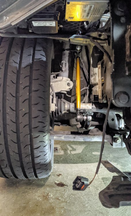
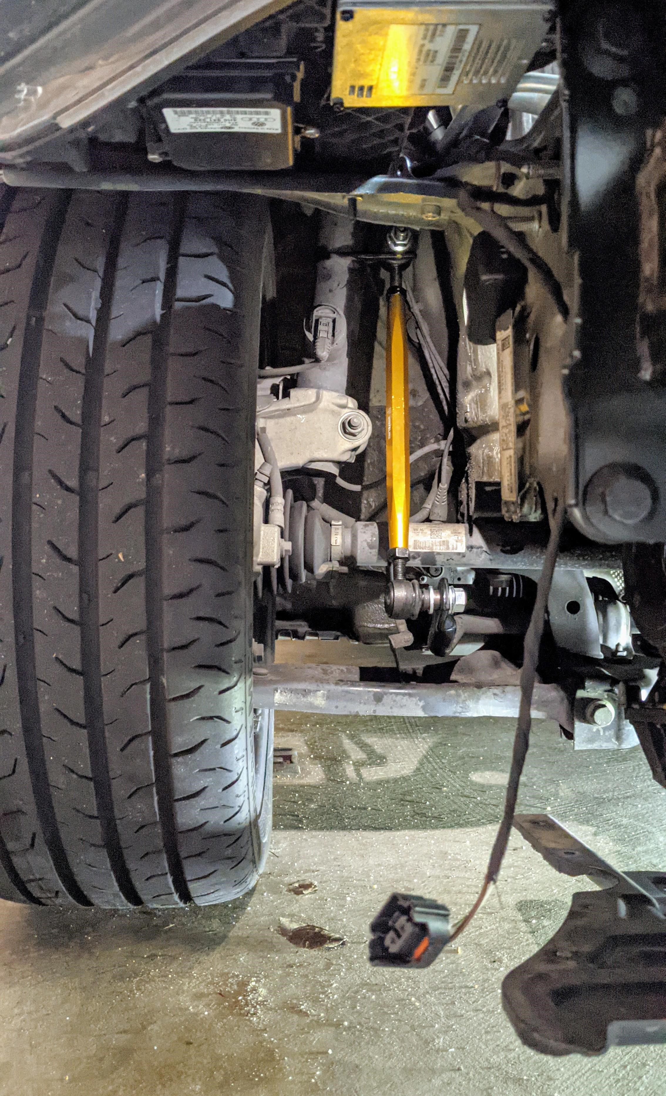
1 pointWeird. U sure it wasn't like that before the endlinks were fitted? I didn't have any change in suspension height when I fitted my Whiteline frontend links.
 1 point
 -
So I'm replying to this thread for the record, so that others may learn from my experiences (that's if people search efficiently!). I actually used this thread to help me. For context I changed my 1KD discs and pads over the past two weekends. They were original pads and discs for 65 plate and 83,000 miles. Based on my experiences from changing the front pair (3 or 4 years ago) I was ready for a fight. Unfortunately no photos because dirty hands and no time to waste! My research already highlighted that the facelift version (after 2017 ish) of 1KD had different "depth" of disc hub (see photos someone above posted). The 1KD pre-facelift you can remove without removing the caliper carrier. I used ATE catelogue online to narrow down discs and pads - yes I splurged out on ATE, overkill on rears but there was an offer on. I also purchased a "brake caliper repair kit TRW SP8980" (from autodoc) which came with slider pin grease sachet, piston seals, dust seal, caliper pin rubber boots. This was just in case that I found broken rubber bits. Turns out even after 11 years and 83K miles, they were all fine to reuse. But I replaced caliper pin boots because I couldn't be bothered to clean them out and it meant I could be rough with them. So this thread has already explained how to do it. My tips are: Go to town with wire brush as you are dissassembling. Rust will be everywhere and it is an excellent opportunity to inspect suspension and behind the hub. Using drill attachments makes the job much quicker but use eye protection as the wire bristles will fly off. I mostly brushed around bolts and nuts. Not aiming for a shine, just removing loose flakes and leaving the rust patina. Put more effort into the brake pad carrier guides and the wheel hub before mounting new disc on. One man brake bleed kit is about £8 from Halfords (the tube is most useful - you can use an empy milk bottle), especially when winding back the piston, no need to worry about resevoir overflowing. Also good opportunity to flush brake fluid. The caliper rewind tool made the job fairly straightforward (I used Hilka 12700140) I really can't imagine doing this with needle nose pliers. I needed spanner to start it, but afterwards you can use the tool like a fat screwdriver. The hardest bit was holding the caliper steady and making sure not to twist the rubber dust bellow and having it concertina folded correctly. I used copious amounts of brake cleaner to make it "slip" easier and to clean gunk away. Also, pay attention when it is pressed all the way in because there is no "stop" to the rewind. I was rewinding for at least 5 minutes before I realised I was at the end. The reason this took two weekends was because the old brake disc had seized strongly to the hub. I was mentally prepared for this after my experience with front pair but after 25 minutes of hammering / tapping I was scared of damaging the hub or fracturing the disc (undrivable!) so I gave in, put the new pads on so I could drive and ordered a brake disc puller for £55 from Amazon (I imagine cheaper ones are available) - I figured I would have to pay way more than that if I had to take it to a garage. Using this it takes about 5 minutes to remove disc with a satisfying "thunk". I used a bit of plywood to protect the hubcap and had to bend the metal dust shield to get the "claws" around the disc. I also recommend using some rust converter and/or protector spray after you have finished brushing and before assembly. Jenolite is popular and is available on amazon. This is an excellent time to adjust the handbrake slack, because you can see and remove the attachment to the caliper so you won't be fighting the tension (as much) as you adjust the nut. The bottom caliper slide pin screw is easy to torque (35 Nm) but the top one is harder to access unless you have a shorter torque tool or use extension to get through the suspension coil. Or you can gauge by feel after doing the first one. I used ceramic grease as anti-seize (I don't care if it's not the correct type of anti-seize, it'll be better than nothing) between the hub and the brake disc AND between the brake disc hub and the wheel. I think that's it for now, the brakes haven't bedded in but if I have a serious failure I'll be sure to report back!1 point
-
1 pointThe 3T is a keeper at that low mileage. You could quite easily add car play I’m sure. The occasional ULEZ charge hopefully won’t break the bank. The TSI I purchased about six months ago. Hardly done many miles, too early to say it’s a 23 plate at just under 50k. And had an approved warranty for 2 years.1 point
-
@Evolution13 Yes, this is a completely different car1 point
-
1 pointDon't know if it's the same on the Mk4 but a rear wiper was available on the Mk3 hatch?1 point
-
My O2 have Retrofit tpms and ESC I Hope at night i have time1 point
-
I change mine twice a year and only change the filter on the third change because taking that under cover off on the drive is a tricky job if not on a ramp. I use a vacuum pump for oil changes when not changing the oil filter It's so easy.1 point
-
1 point@Rbz5416 Interesting I'll give that a try. I've assumed I was Primary user. I have recieved another email from VAG Digital Support this Sunday afternoon. Had to send another route to the car, and then send the App logs to Digital Support. There is a hidden feature - shake your phone and a Support Menu pops up and you can send stuff to Digital Support.1 point
-
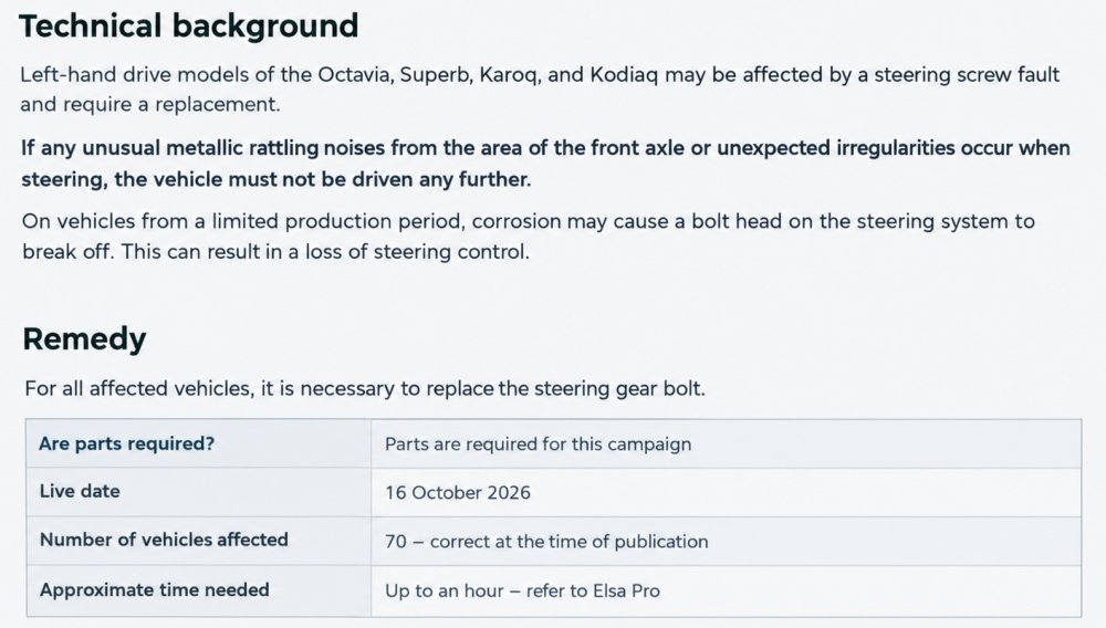
1 pointGalvanisation is possible only when is steel in contact with aluminium, moisture and salt. On my car and on any car with steel subframe bolt is not corroded. Anyway for my own sake, i will change both bolts by myself, not only one of them. Check by your vin https://www.skoda-auto.com/services/recall-campaigns1 point
-
Just a little update. After all the information and cross referencing part numbers I’ve just fitted a Blue Print ADV182301 fuel filter. Fits perfect for my housing and at sub £10 from Amazon can’t grumble.1 point
-
1 pointI stopped using Eco mode as the lack of engine braking when coasting meant I was using the brakes more - it made no measurable difference to mpg but used more brakes, so it seems to me like Eco mode will increase running costs without decreasing emissions?1 point
-
1 pointMy daughter has got the Kamiq SEL with 18" alloys and no spare. We removed a wheel and test fitted. An 18" alloy fits into the spare wheel well but is a tight fit. We then bought a foam insert with a sissor jack on Ebay - not even VAG - and it works o.k. I don`t know if y 17" alloy may fit.1 point
-
Welcome to the forum. Yes, I have seen other posts with similar clutch issue without loss of fluid. Very likely to be an internal fault with master or slave cylinder seals - best to try replacing the master first - especially if slave is the internal type.1 point
-
1 pointNot sure if this is relevant but: I sent a route to the car yesterday that didn't arrive. When I got to my destination I thought I'd give the Pay to Park a try. Oddly it told me I had to be the primary user. Apparently I've been operating as a guest, which is something the car has done itself. Logged in as Primary User & sent another route, which this time arrived. So may be worth checking your are actually the Primary User & haven't been mysteriously switched to a guest account, which obviously wouldn't be connected to the app. I'm guessing this switching is what produces the random "Your settings have changed" message.1 point
-
1 pointUpdate 1. ŠKODA Customer services replied Friday with email address of VAG Digital Services customer support. Emailed them and got a reply Saturday evening requesting details of how I was using the function. Replied with step by step details of actions taken in the App and screen prints of each step outcome.1 point
-
1 pointThis February 2024 Skoda Storyboard Škoda StoryboardInterior: Six Design Selections, sustainable materials an...› Many packages, individual options and new Simply Clever features › Sustainable upholstery and door panel materials include recycled fabrics, …states that for 'upgraded' Kamiq and Scala models a 8" Digital Display became standard, with a 10" Virtual Cockpit a an option. 8-inch Digital Display as standard, customisable Virtual Cockpit as an optionThe upgraded Scala and Kamiq come with an 8-inch Digital Display as standard on all models. The optional, customisable Virtual Cockpit offers a 10-inch display. As I said above, UK-marketed Fabias now have a 10.25" Virtual Cockpit as standard EXCEPT for the 'entry-level' SE Edition model that has the 8" Digital Display. The trim levels of current-model UK-specification Fabias are summarised here: https://www.motorpoint.co.uk/model-guides/skoda-fabia-models-and-trim-levels-explained The online Owner's Manual for my late-2023-built Fabia SE L has an issue-date of 19.6.2023 and contains no mention of a "Digital Display", whereas the "Driver information system" section in the next Owners Manual chronologically (issue date 15.1.2024) has two sub-sections - one for a "Digital screen" (ie. the 8" Digital Display) and another for the Virtual Cockpit (ie. the 10.25" instrument-cluster screen). Personally, I'd be perfectly happy with the capabilities of the 8" Digital Display. Although my Fabia has a the big (9") infotainment screen with 'navigation', I've no wish to display mapping in the instrument-cluster - a feature that's only possible with the Virtual Cockpit. But, as I also don't wish to pair a phone with my car, nor play music within it, nor have the radio on, I'm probably not a typical mid-2020s car owner.1 point
-
1 pointIn the case of VW and Skoda, the head unit cannot be used to drive speaker channels 5 and 6—at least, I know this for certain regarding the MIB 2 Standard, and it should be the same for the MHI2. Unlike Seat and Audi—which utilize an internal sound system (i.e., the sound system is managed directly by the head unit)—VW and Skoda have always relied on an external amplifier for these channels. Consequently, there is a hardware difference in the MIB 2 Standard: Seat’s circuit board features two audio controllers, whereas VW and Skoda have only one. Furthermore, the hardware circuitry for channels 5 and 6 is entirely absent from the VW and Skoda boards.1 point
-
1 point
-
1 point@Alvin600 I can attempt to look up which parts are involved, using your VIN to make sure that only parts fitted to your specific car will be listed. I'll message you privately, so that you can supply the VIN to me. You're too new to start such a conversation, but you will be able to reply to my message.1 point
-
Its brand new car, just bought it. The goal is to keep it as long as possible, same to the 2018 Fabia. I use it mostly for driving to work only 30km motorway driving and 1-2 long trips per year (more than 500km motorway), I use the other Fabia for rest. I was thinking to do the first one in 5000km and then every 8000km (or 12 months if a year the car does not reach the 8000km), exactly same pattern to my 2018 Fabia. That's a good strategy, so the first oil/oil filter change in sub 1100 miles (1800km) on both of your cars, and then 7000miles (11 000km) or 12 months, whichever comes first!1 point
-
1 pointAs far as I'm aware, all Skoda Fabia Mk4 cars (irrespective of age) SHOULD have adaptive cooling shutters. They were referred to in this February 2021 Skoda Storyboard relating to the then-new Fabia https://www.skoda-storyboard.com/en/press-kits/skoda-fabia-covered-drive-press-kit/aerodynamics-innovations-increase-efficiency/ and the information provided reads as follows: Cooling shutters save up to 0.2 l of fuel per 100 km at 120 km/hThe addition of a new type of cooling shutter has been an important measure. These shutters are actively adjustable slats in the front bumper’s lower air intake. When there is little need for cooling, they close automatically, thereby improving the car’s aerodynamics. This results in fuel savings of up to 0.2 l per 100 km when travelling at a constant speed of 120 km/h. To allow for a high level of cooling or to accommodate short stops, the system opens the shutters so that the maximum amount of air can flow in. Also mentioned in this October 2021 Skoda Fabia link https://www.skoda.co.uk/news/details/skoda-fabia-setting-benchmark-in-its-segment Cooling shutters improve fuel consumption ŠKODA has installed cooling shutters in the front bumper’s lower air inlet – the first time this technology has been used in this vehicle segment. To improve aerodynamics, actively adjustable slats automatically close when there is little need for cooling. To allow for a high level of cooling or to accommodate short stops, the system opens the shutters so the maximum amount of air can flow in. To further reduce drag, a larger roof spoiler and side finlets optimise the airflow at the rear. At the front, the air is guided through vents in the bumper, known as Air Curtains, in a particularly aerodynamic manner close to the side of the body and the wheels. Twelve panels now cover a larger part of the underbody instead of three, especially in the areas that are crucial for aerodynamics, such as the engine bay and the axles. (I don't know exactly where they are or how they operate - there's nothing obvious I can see when I look through the bottom and top radiator grilles.)1 point
-
I’m guessing you plan to keep the car for many years, so make sure the service interval is set to Fixed so oil and filter changes are every 12 months or 10,000 miles. Nothing to stop you doing oil and filter changes more often though. I bought my 2023 Karoq (in April 2024) with 1,080 miles recorded, selling dealer included an oil and filter service as part of the presales prep. When I bought our 2015 Fabia in 2016 900 recorded miles and 1 year old, from a car supermarket so no pre sales prep, I had my local independent do and oil and filter change immediately. Karoq does around 7000 miles a year and the Fabia around 2000 miles a year both have annual services though.1 point
-
1 point
-
Just to answer my own question, should it be of use to others, yes - the iPhone pro max does fit in the phone charging bays 😊 (I bought one anyway). It fits pretty much perfectly (with a thin apple weave style case on) and I suspect it was designed to do so. Any bigger a phone, or a bulkier case, and it probably wouldn’t.1 point
-
Hi, I finally installed the cruise control. It works perfectly. I had to run an extra wire. Finally, I programmed it using ODIS.1 point
-
1 pointJag sales up by a quarter ! Maybe buyers getting their last diesel models before deletion. Dead cat bounce !1 point
-
1 pointI don't think that's correct. The only MQB cars with an alu subframe are the S3, RS3, GTI CS, R and top spec hot Cupras. I'm reasonably sure the vRS, GTI and nothing else has an alu one, let alone the Karoq, Kodiaq or whatever! I've got an issue with my steering (knocking from steering column/dash when wiggling side to side), so will be getting the car on a lift on Monday. It's unrelated, I'm sure, but talk about timing!1 point
-
1 pointMistakes happen everywhere. What really matters is how they deal with them. If contacting support doesn’t get you anywhere, I’d try sending a formal complaint through their official channels, with your order number and a clear explanation of what went wrong.1 point
-
1 pointSee Occyvrs's 2nd post on page 1, with info from internal VW comms:
 1 point
 -
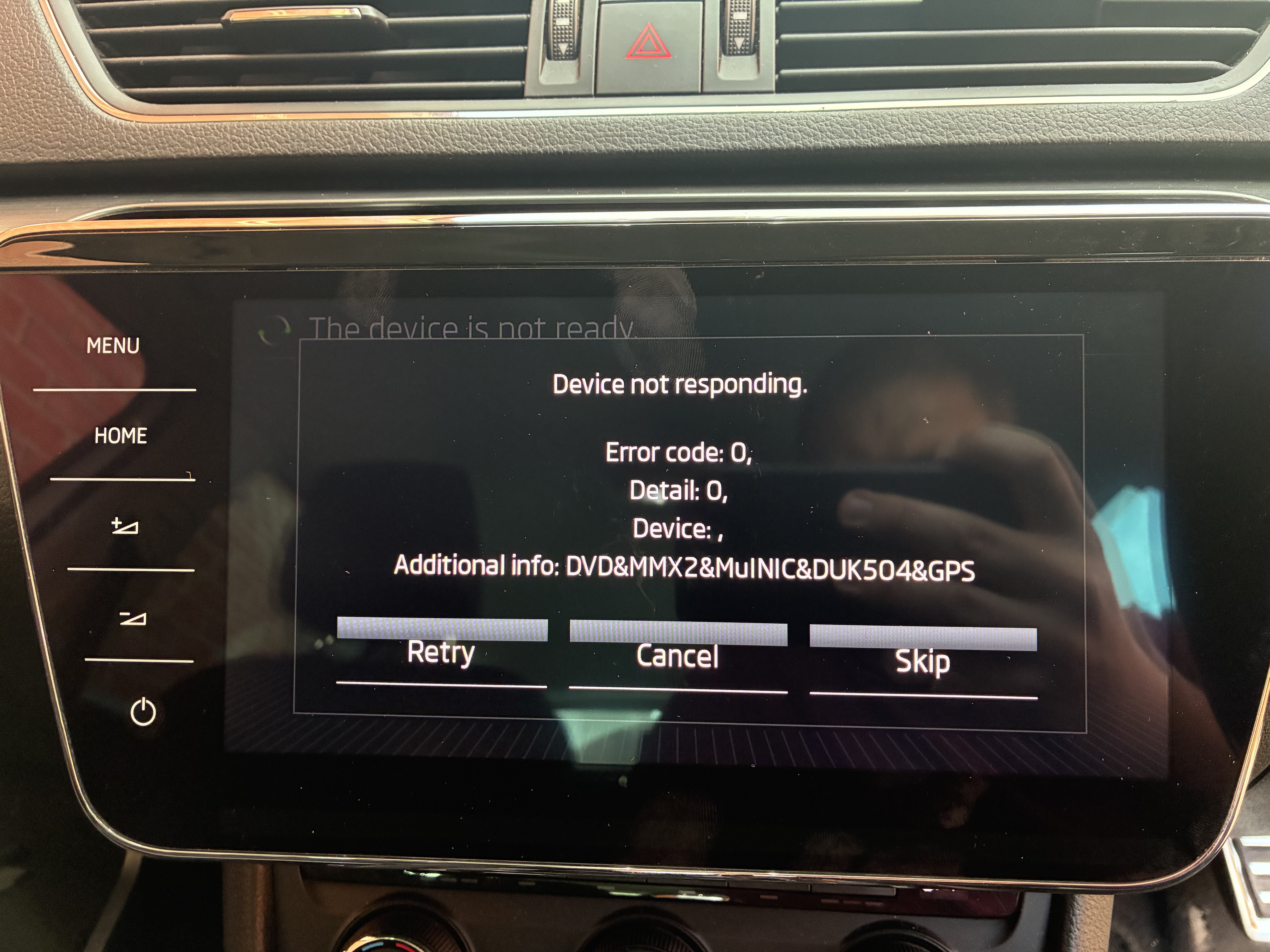
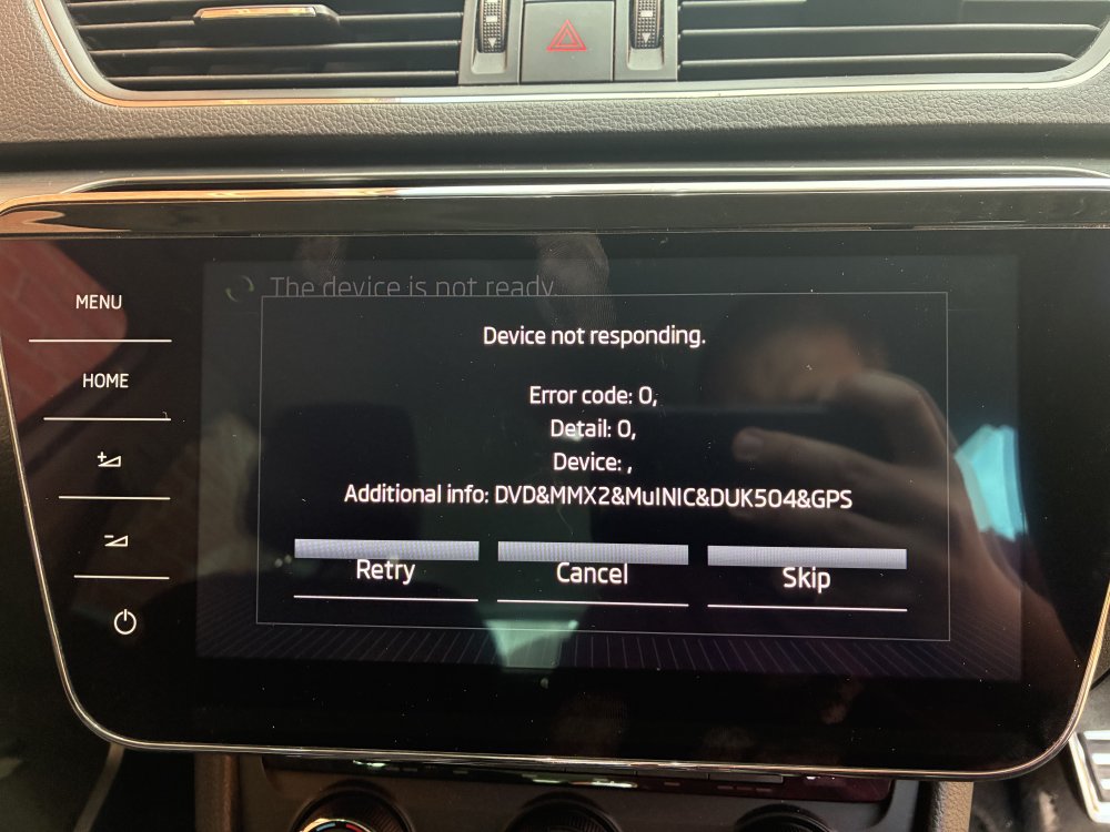
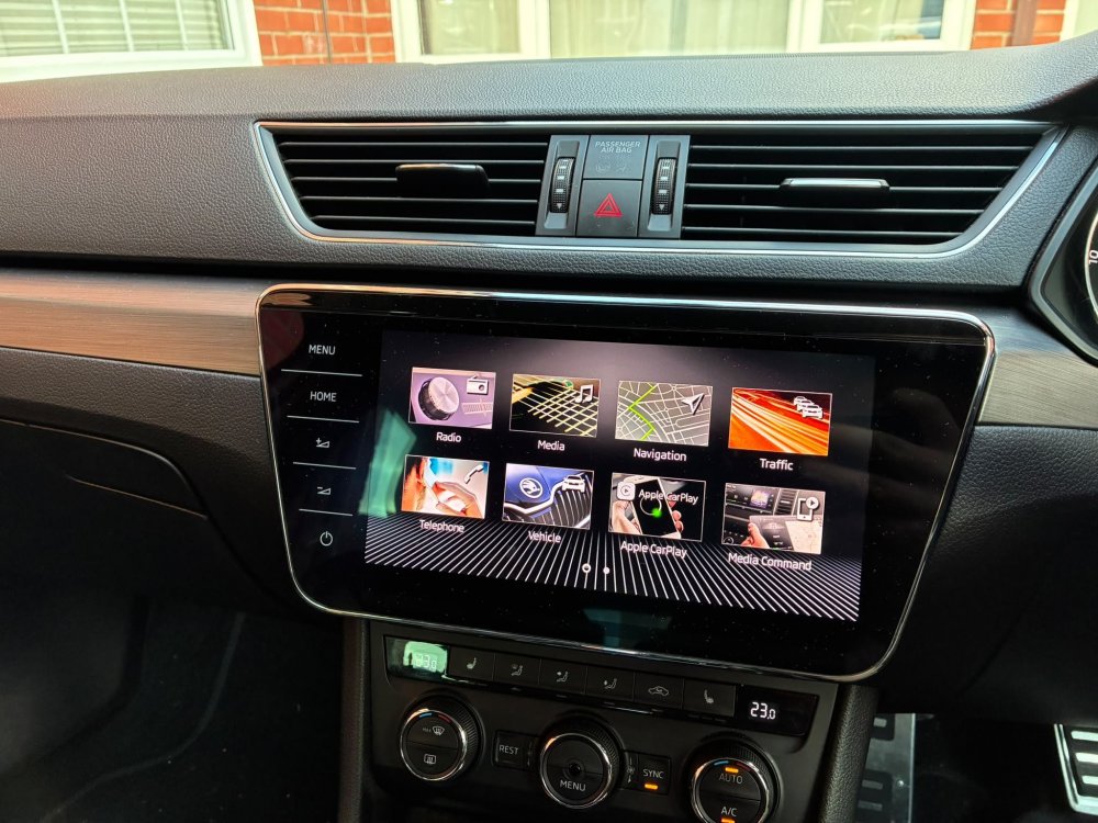
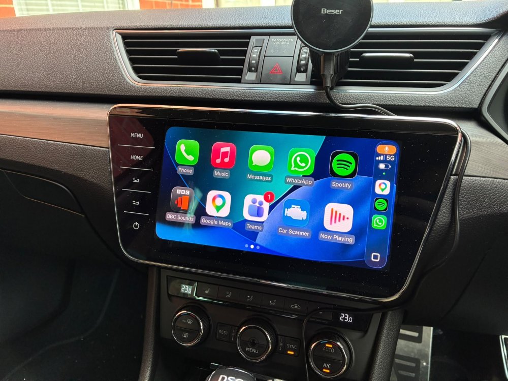
So, now it is resolved, it is time to tell the saga of my MIB2 to MIB2.5 upgrade. Its something I had ummed and ahhed about for some time, but a cheap scrfeen caught my eye on eBay. £150 was too good to pass up. So it was promptly ordered along with a fresh SD card. All files we're downloaded and prepared as per the github and @JR RS guide. I very nearly bought myself a new battery charge from Amazon but thought I would save a few pennies and I borrowed a battery charger from a neighbour. This I think was the major mistake of this story! One evening I set to work. All seemed to be going well. Progress was happening as it should and the new screen was swapped in. And then... Dammit. That looked catastrophic. But this screen is expected (without as much additional info I must note) and all you have to do is press skip. But the screen did not respond. The MIB unit fans were running flat out and it wouldnt turn off, reboot or anything. Hard reset pulling the fuse just brought me straight back to here. In the time I was pulling about scratching my head thinking of what to do next, all the lights went out.... The borrowed battery charger from the neighbour just wasn't up to the job of keeping the battery topped up. (The only root cause for the error I can fathom is that at some point during the flashing, the voltage reduced to a point that power dropped from the MIB at a crucial moment.) My inital thought process was that the screen was faulty as the digitizers can be fickle. So this screen was returned and the next cheapest screen sourced. A few days later when it arrived I plugged it in and....nothing, straight back to this screen. So I then reached out to the Guru that is @pab567. And I must say the service and support I received was second to none. He guided me through connecting via UART so that he could remote access to me to try to reflash the unit. No joy. The EEPROM just couldnt be communicated with. So the unit was packaged up and sent to Poland for some open heart surgery. Unfortunately this was not successful, having successfully recovered the RCC, the MMX recovery failed. And direct programming of the EEPROM also failed and it was deemed uneconomical to repair. ☹️ PAB sourced a second hand native MIB2.5 skoda unit locally to him for signicantly cheaper than I could source in the UK, and for a very reasonable fee prepared it to be plug and play for my car. This was delivered today and we are now back up and running. The final piece was to install the alternative trim panel to close in the gap above the screen. This was sourced from eBay. I popped a bit of the current trim off to find the colour code and managed to find a match for a pretty reasonable price. Note the part numbers are 3V2858418E for no ambient lighting and 3V2858418F with ambient lighting. THe following 3 digits are the colour code, in my case NF8. So the moral of the story is, don't cheap out on not buying a battery charger, check the state of charge before starting, and dont try to do software flashes in the dark!
 1 point
 -
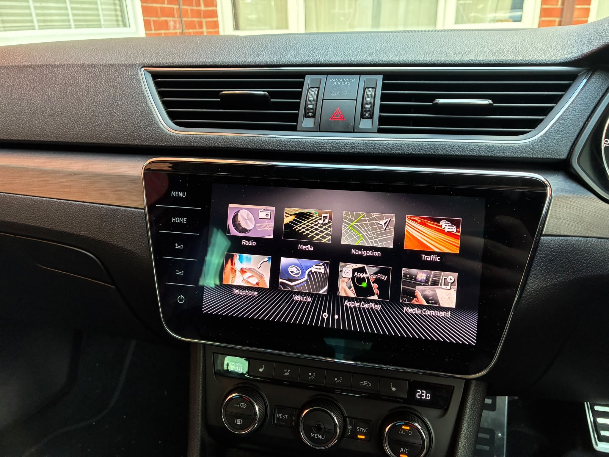
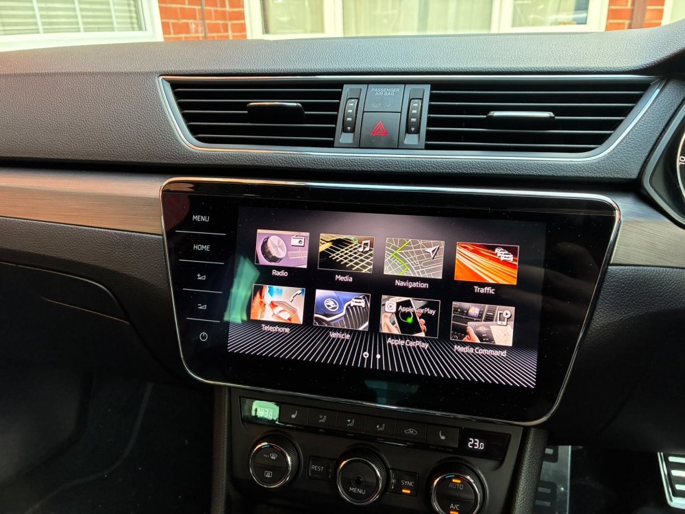
Managed to finish the upgrade of MIB2 to MIB 2.5 today having managed to completely brick my original MIB. Thanks to @pab567 for providing a replacement plug and play unit. Cannot fault the service!
 1 point
 -
1 pointTo be fair, I’ve ordered from Autodoc a few times and never really had any problems with them. Guess it depends on the situation, but I can see why you’re frustrated, especially with return postage costing that much! Definitely something worth checking before ordering, just to avoid getting stung like that.1 point
-
1 point205/55R16 6Jx16 ET35 isn't in the car's CoC (Certificate of Conformity)...hence it isn't approved by Skoda. 205/55R16 6Jx16 ET35 could be used as a spare because spare wheels don't have to be in the CoC...but this is an economy measure, so it would be better to use a wheel specification that's in the car's CoC. In strict European countries, the wheels on the car (not including the spare wheel that's used as a temporary get you home measure) need to be in the car's CoC. So if it's 16" wheels on the Kamiq, the only specifications are 195/60R16 6Jx16 ET35 (winter tyre size, but can also be used with summer and all-season tyres), 205/60R16 6Jx16 ET38 and 205/60R16 ET40.1 point
-
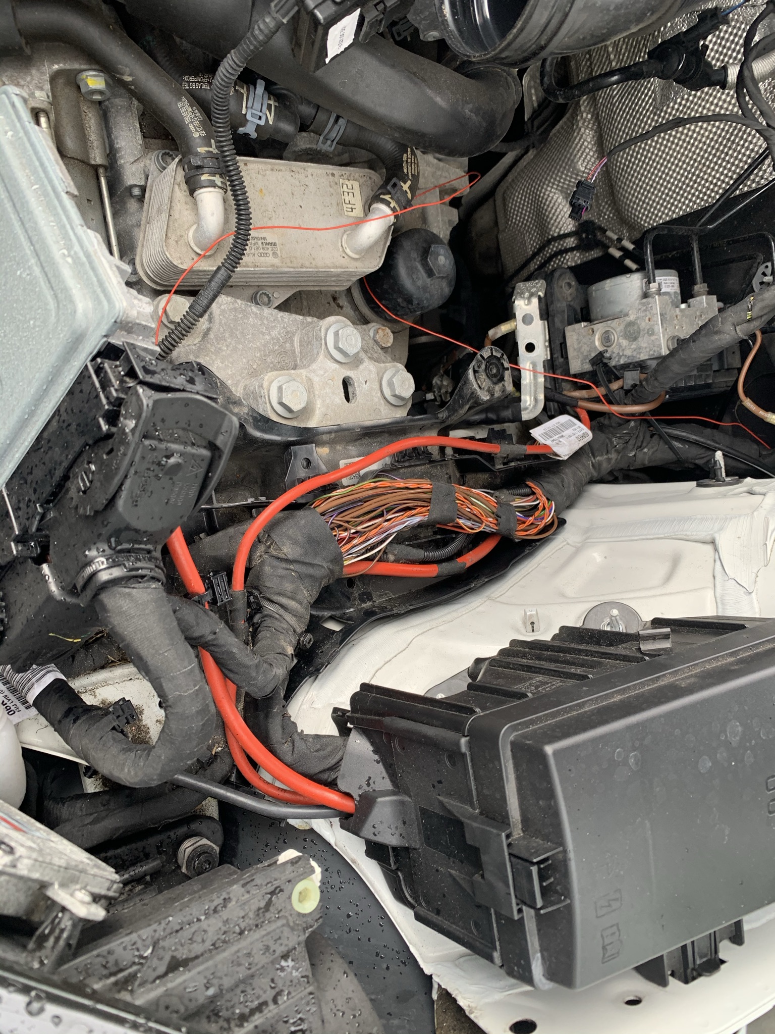
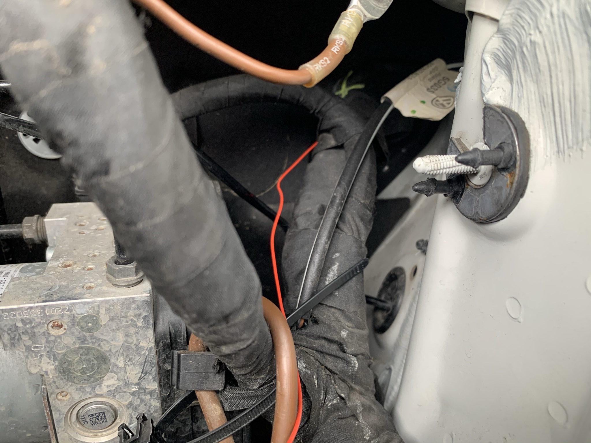
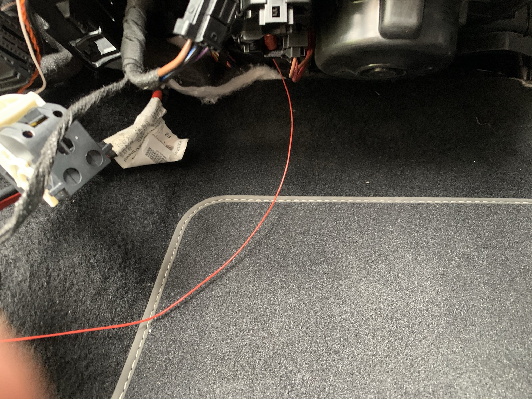
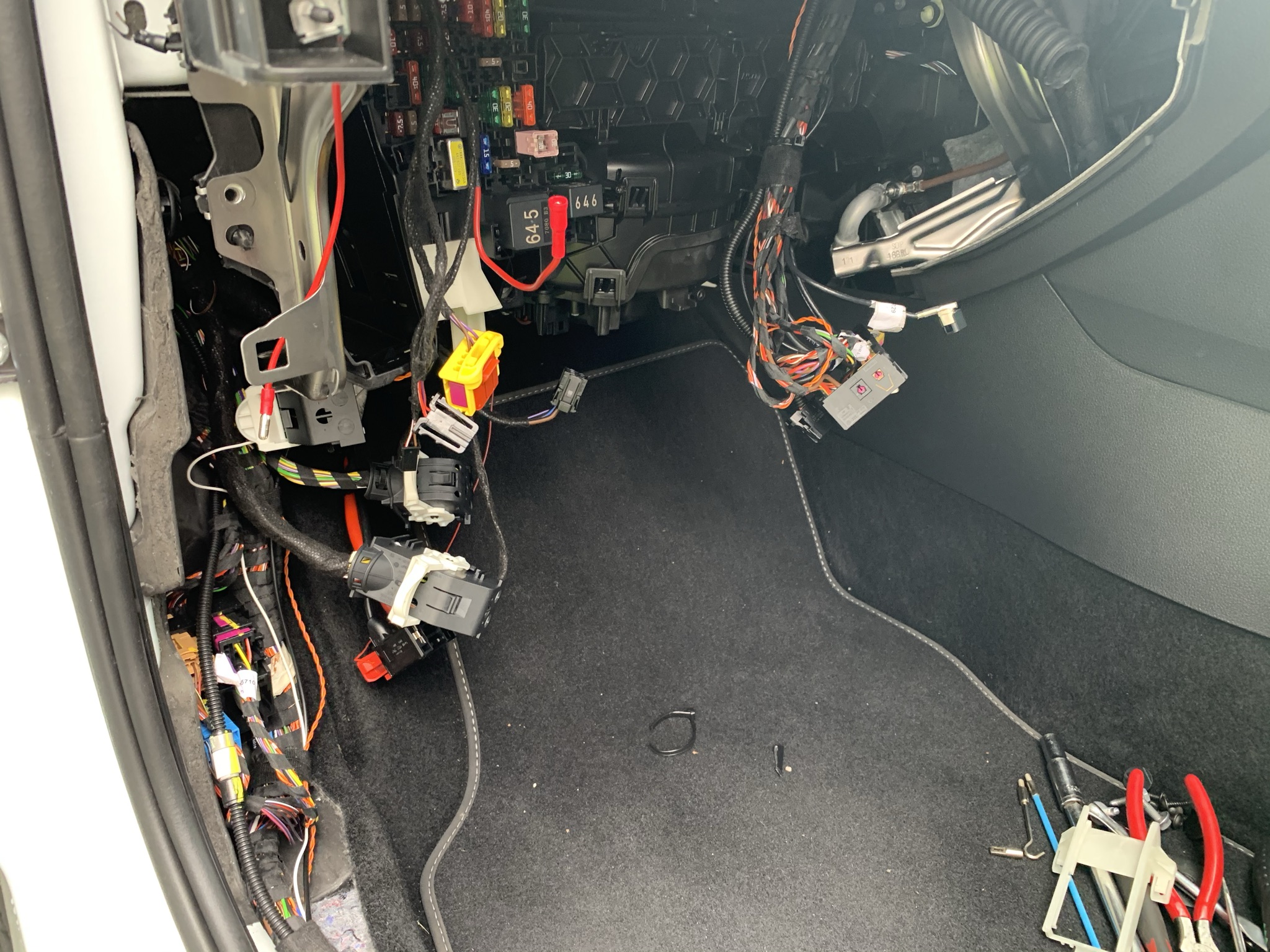
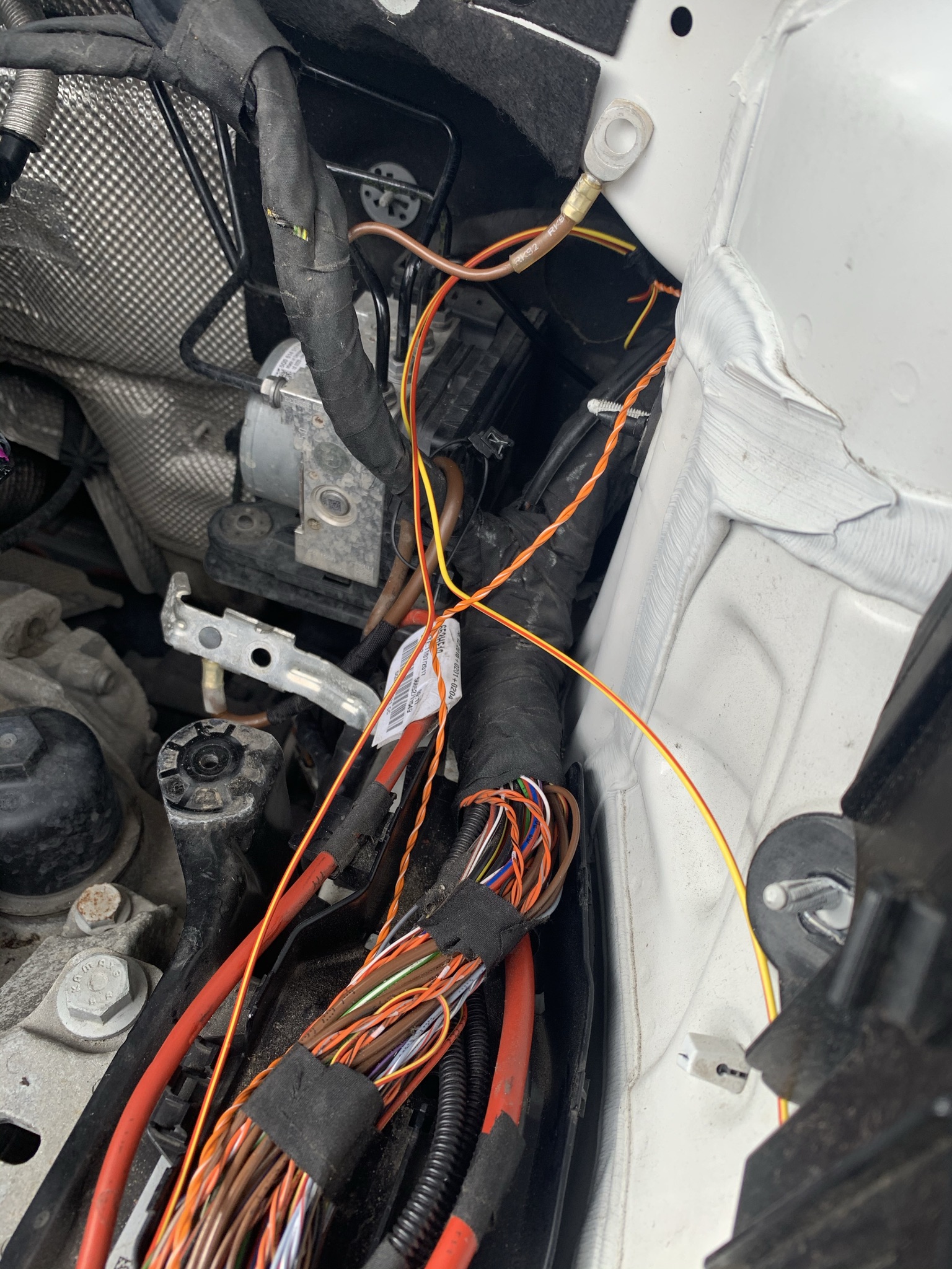
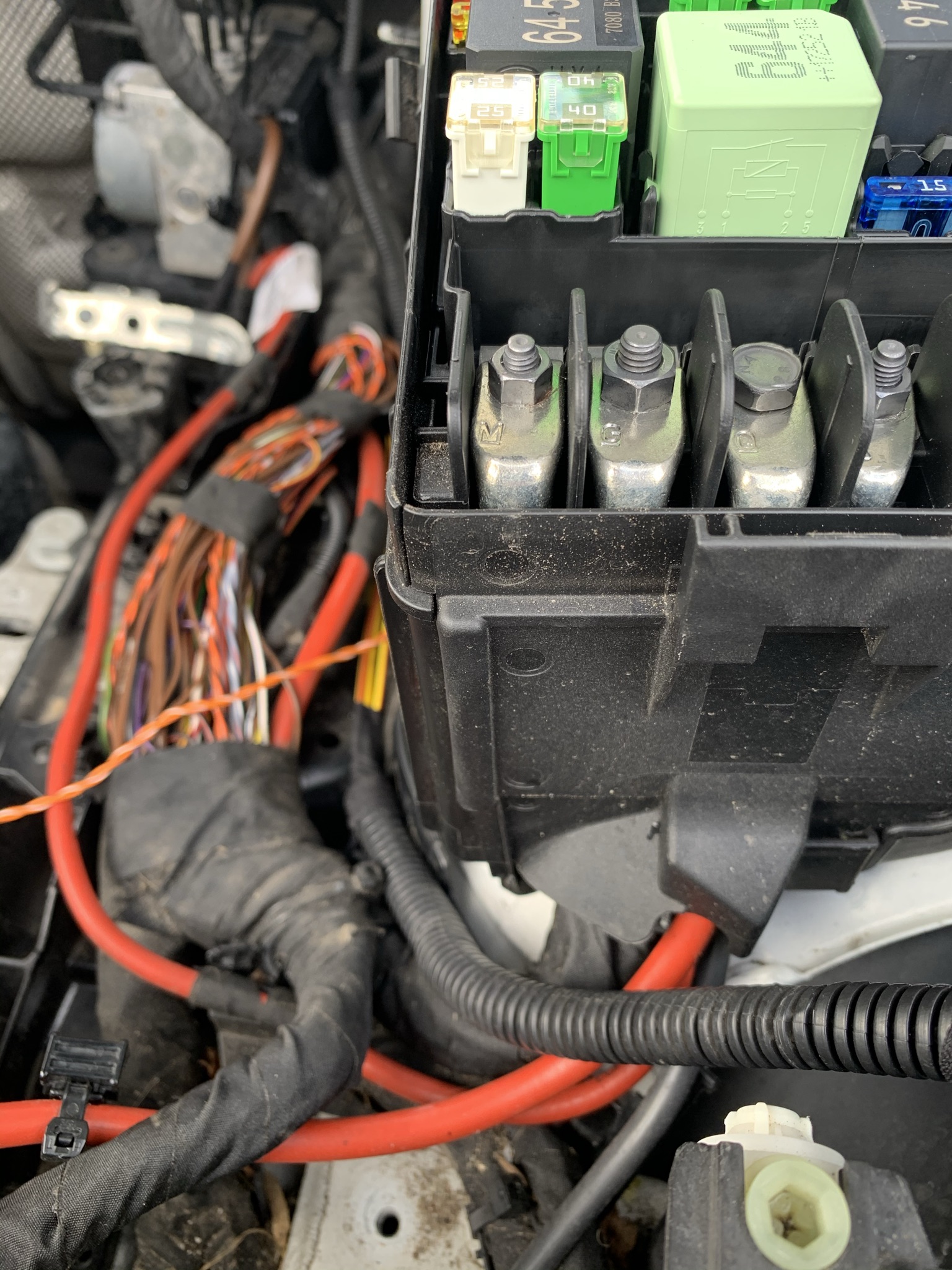
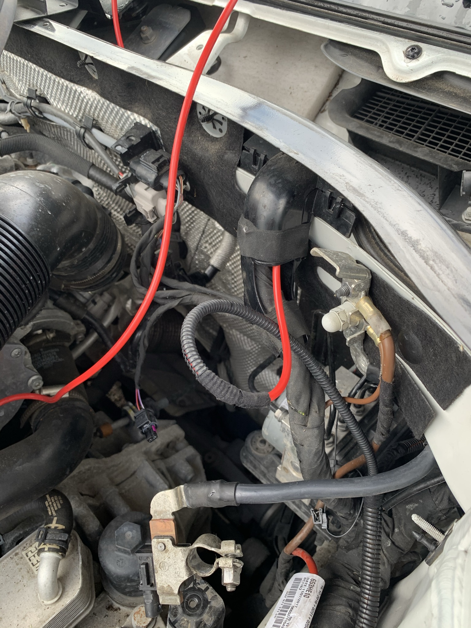
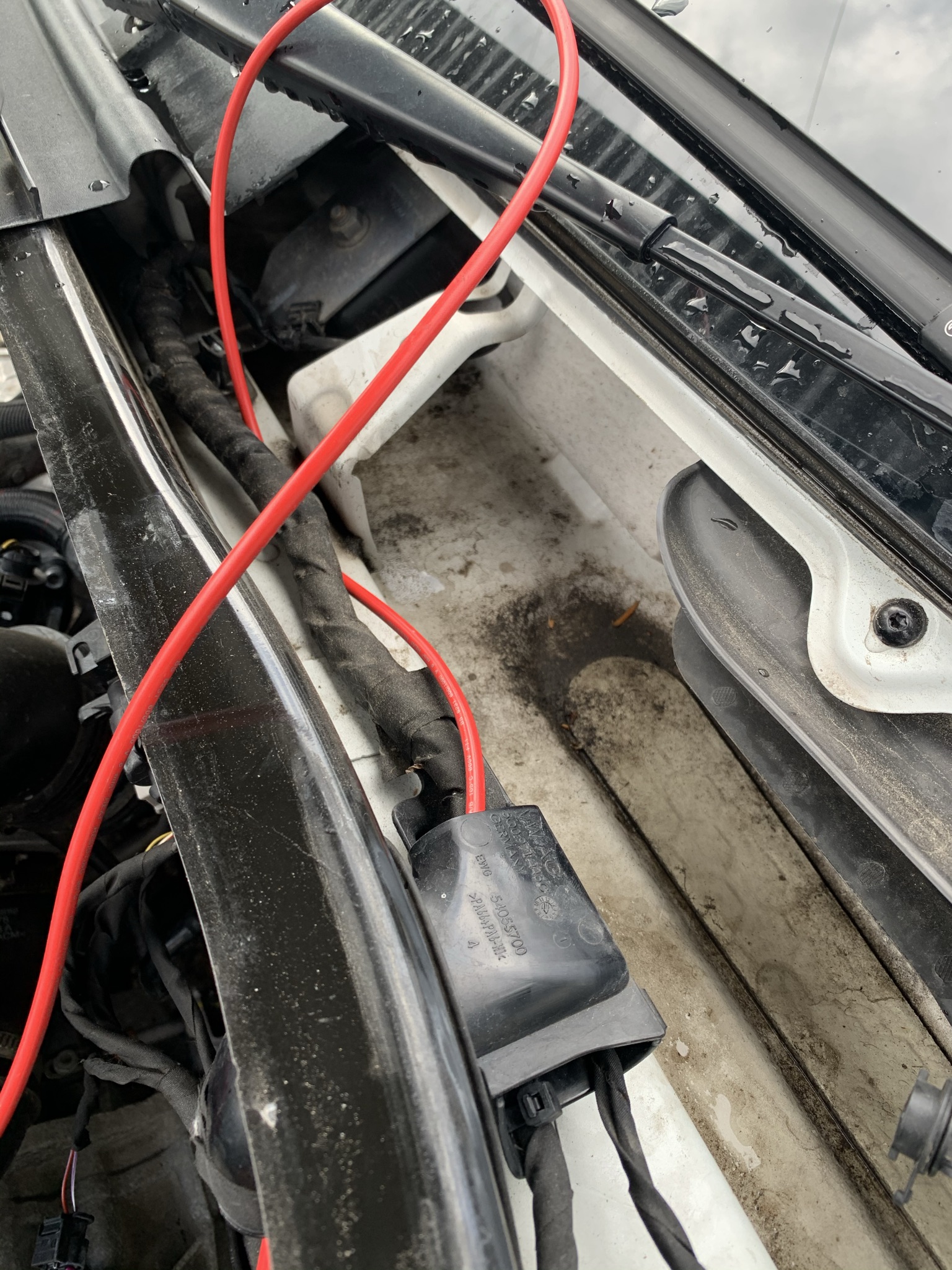
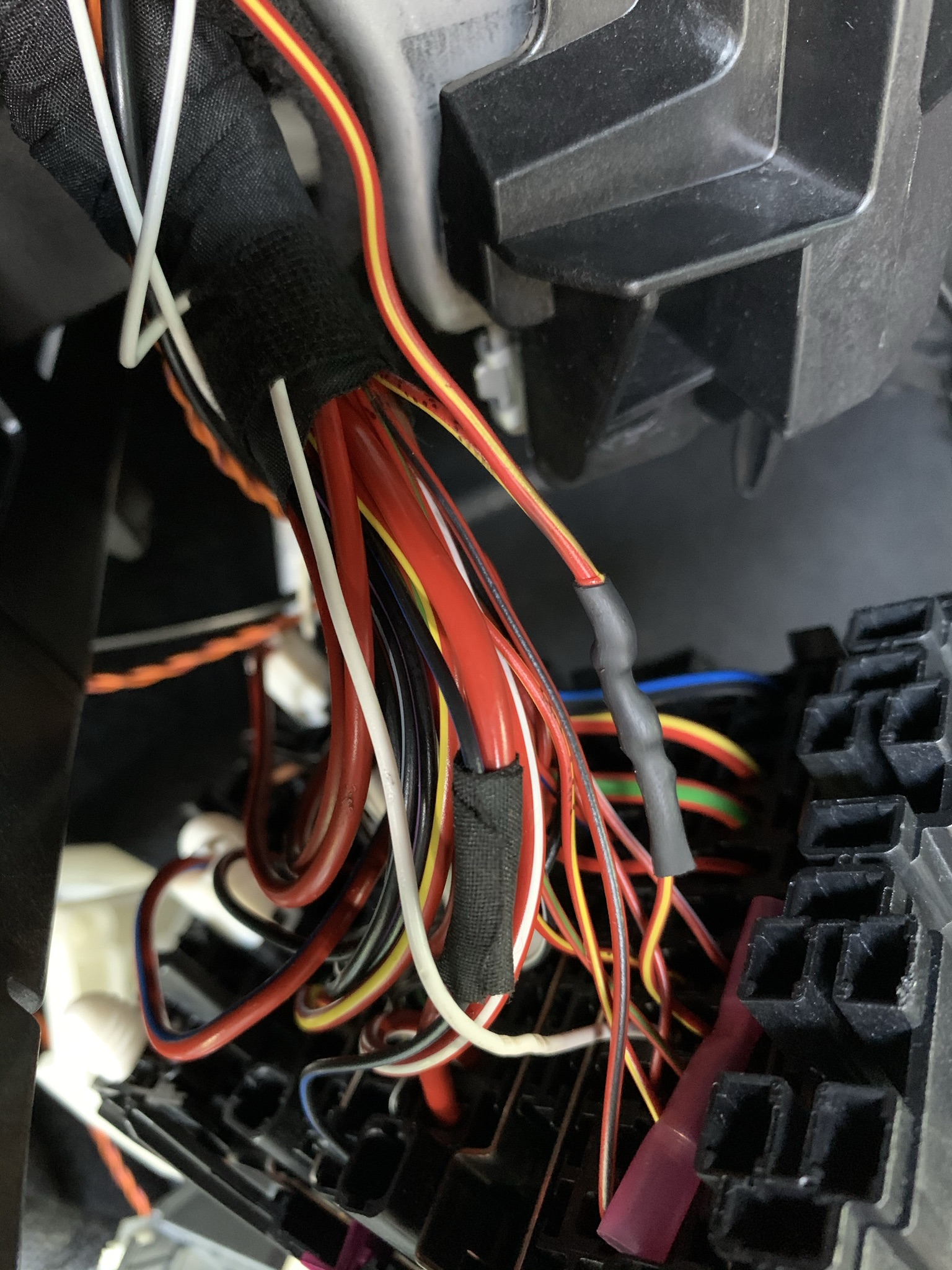
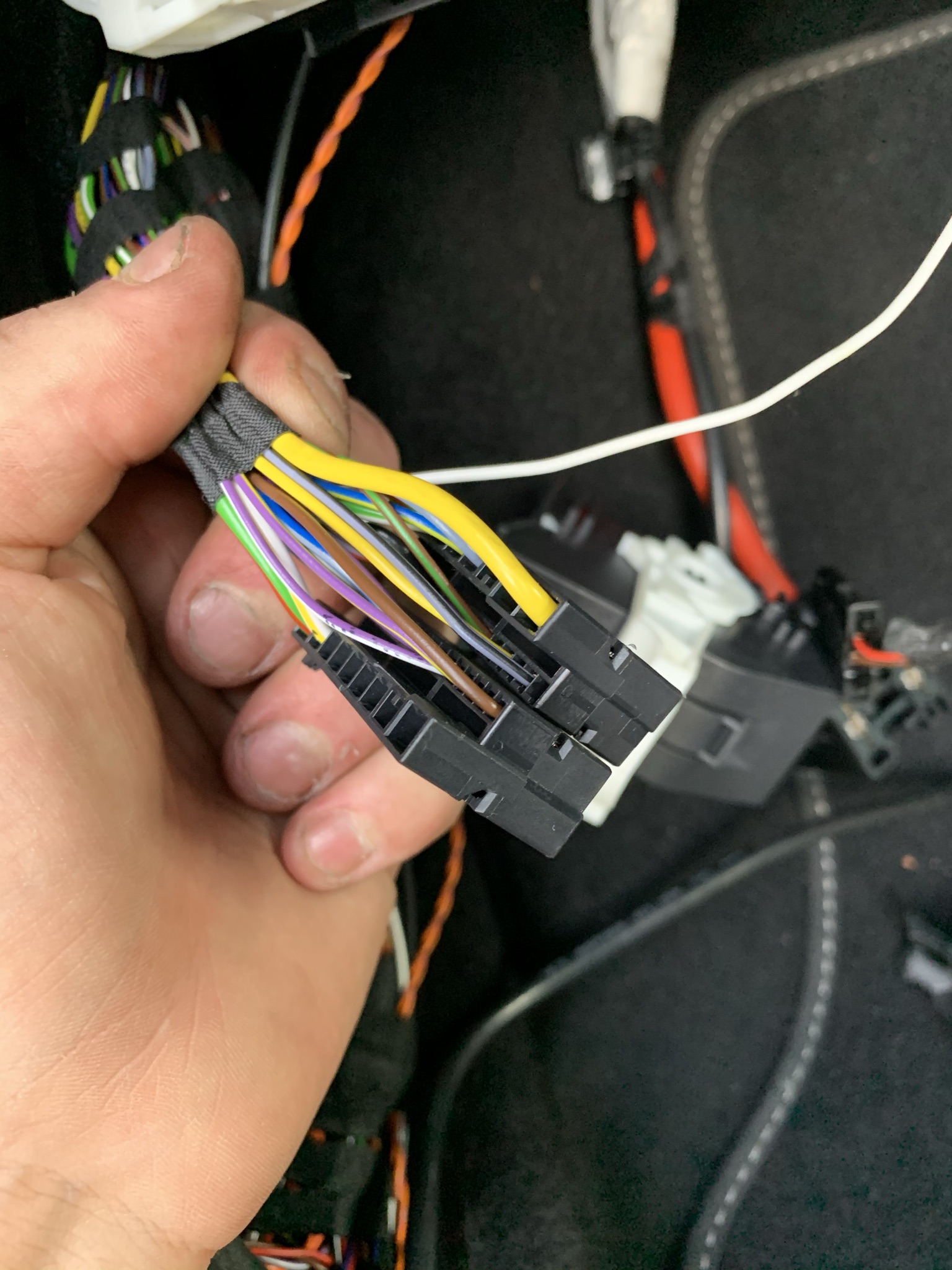
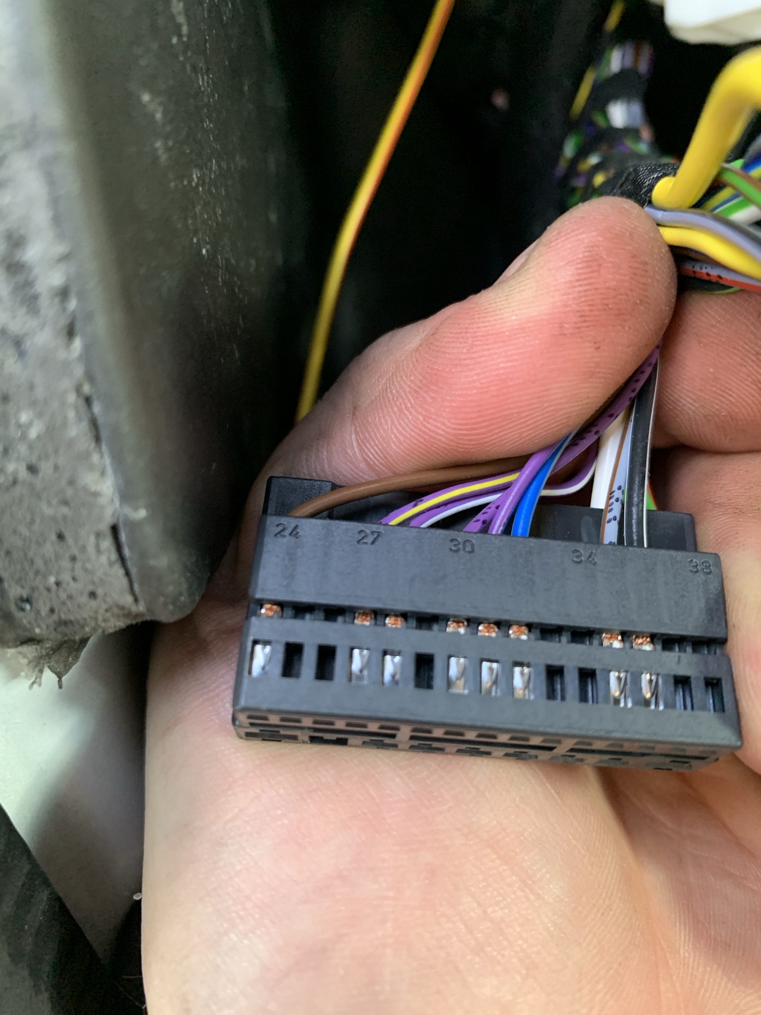
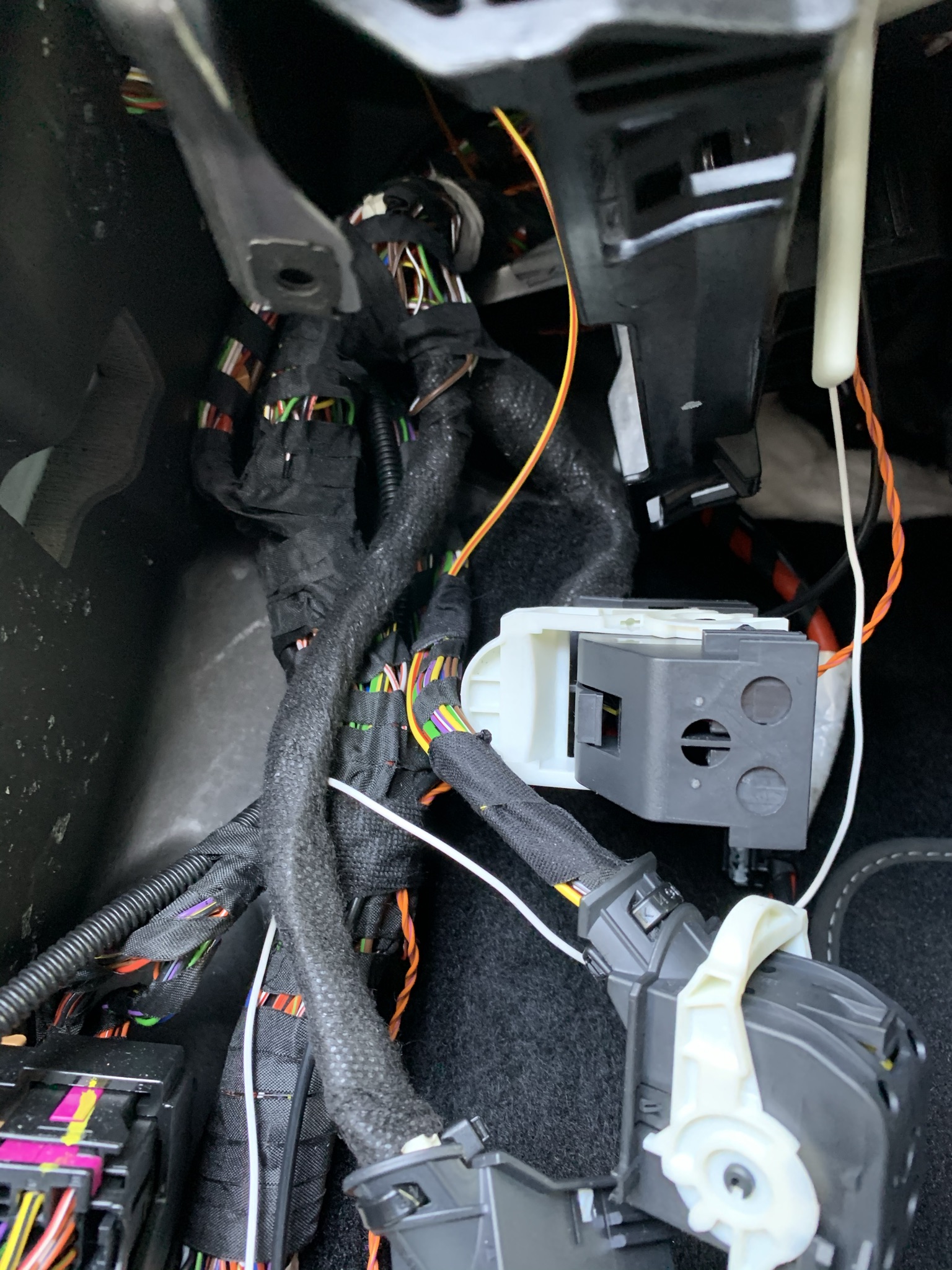
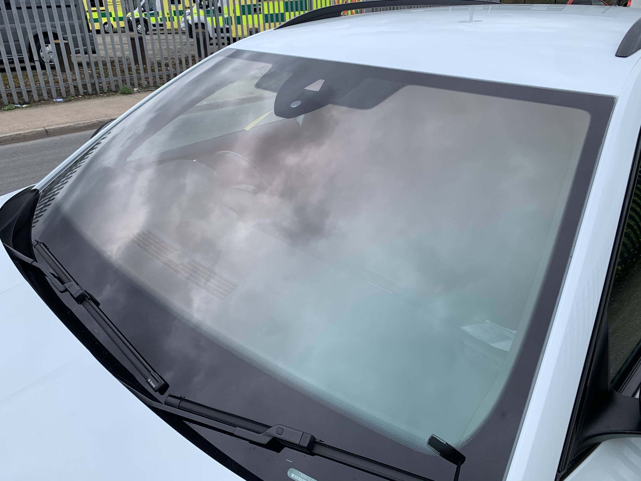
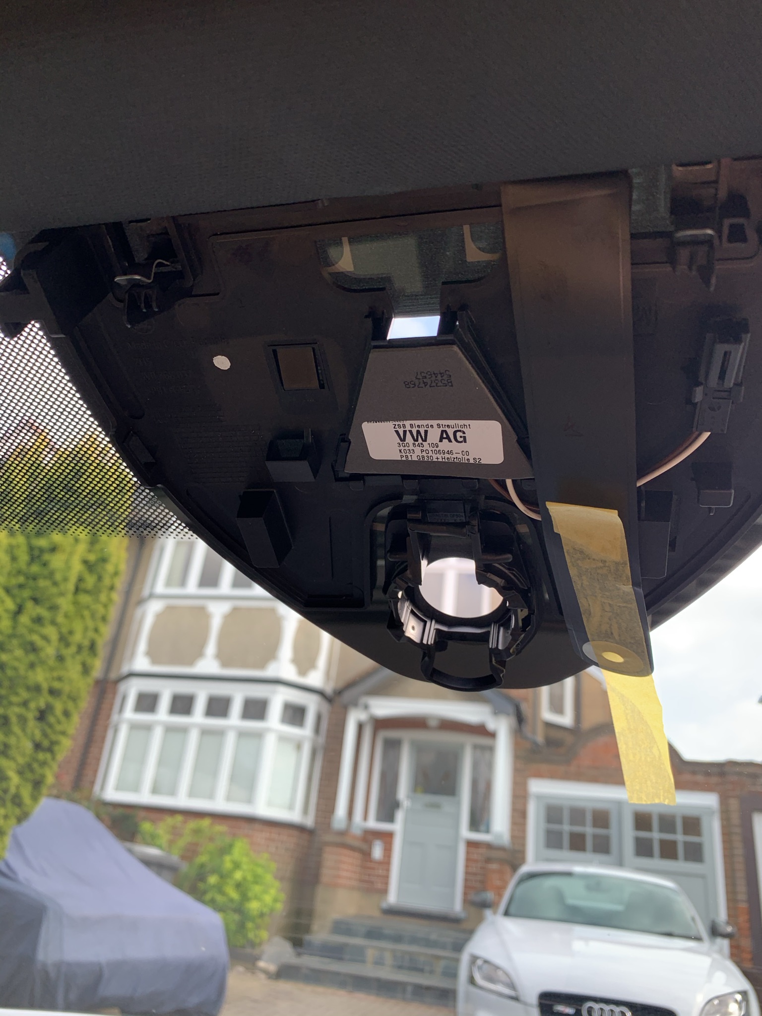
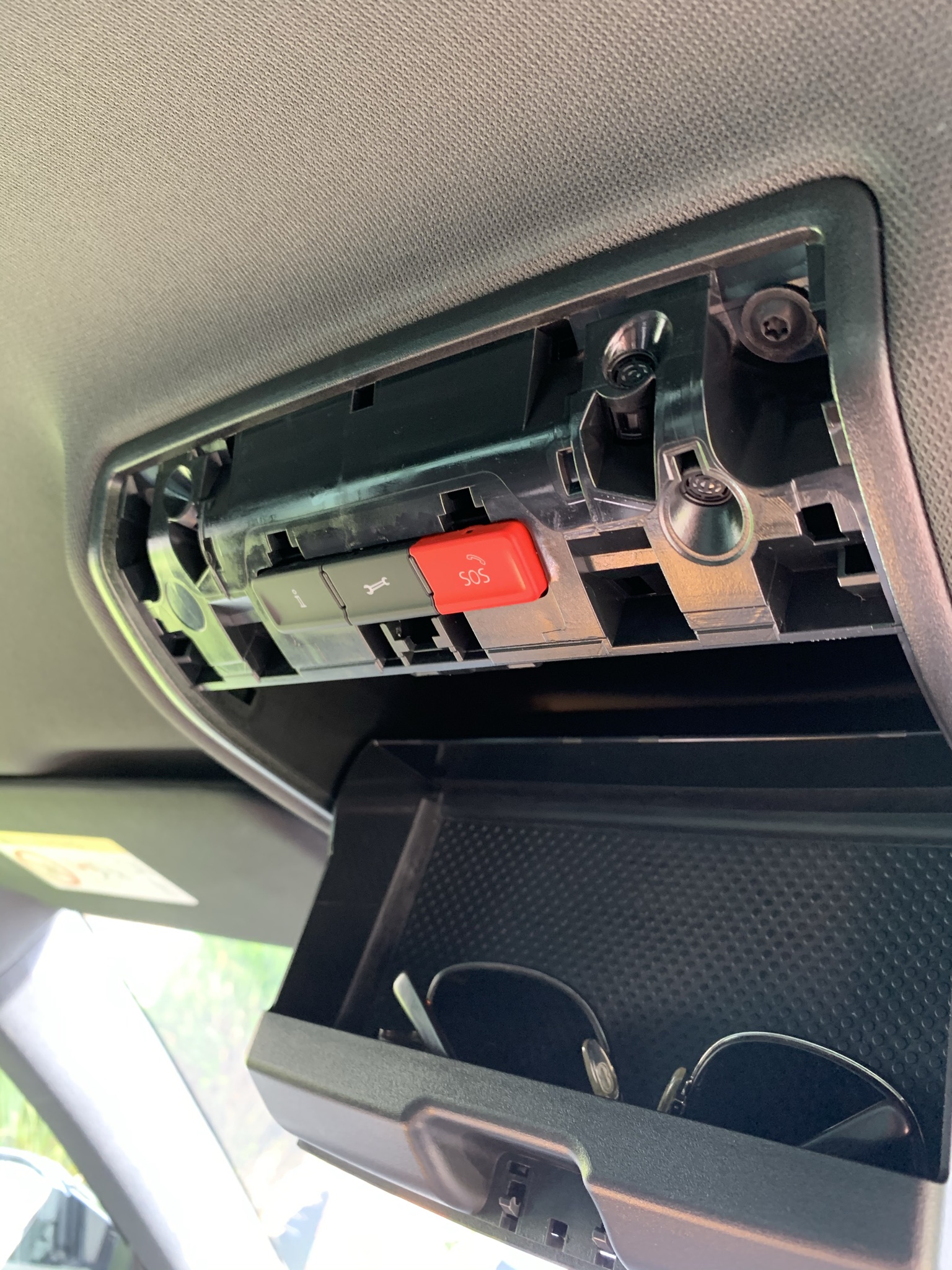
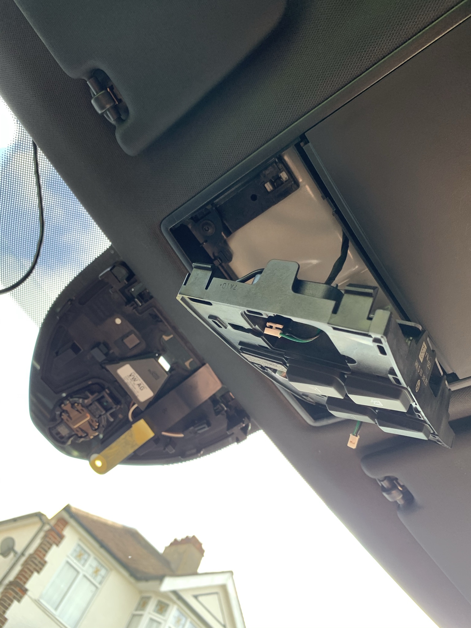
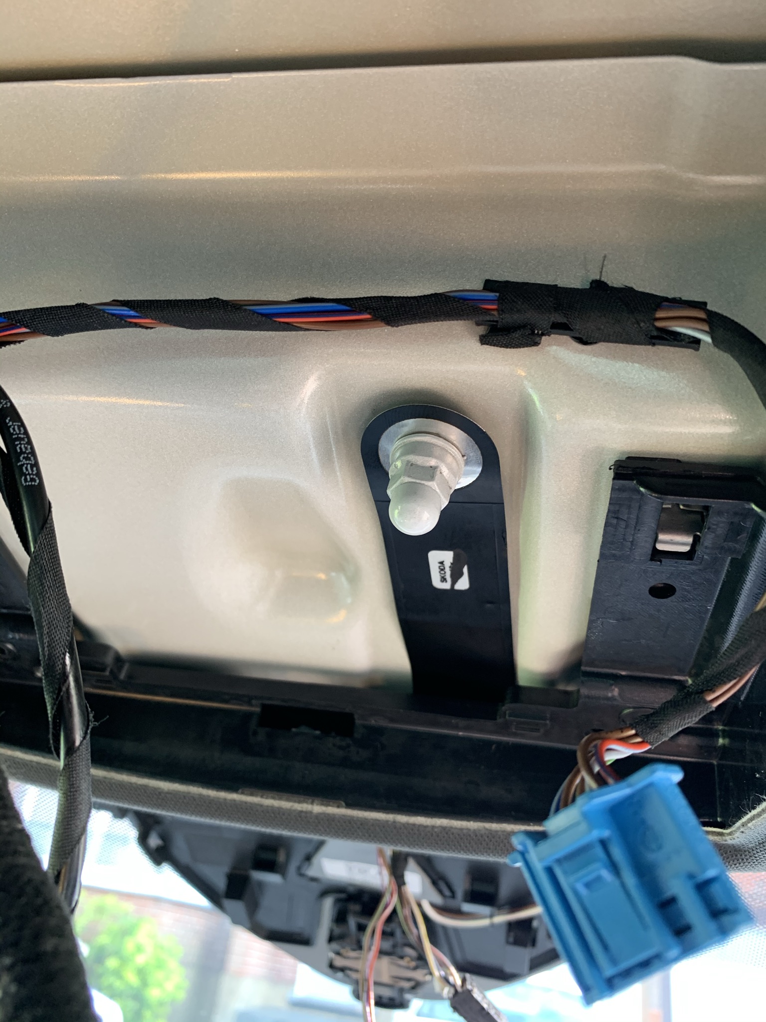
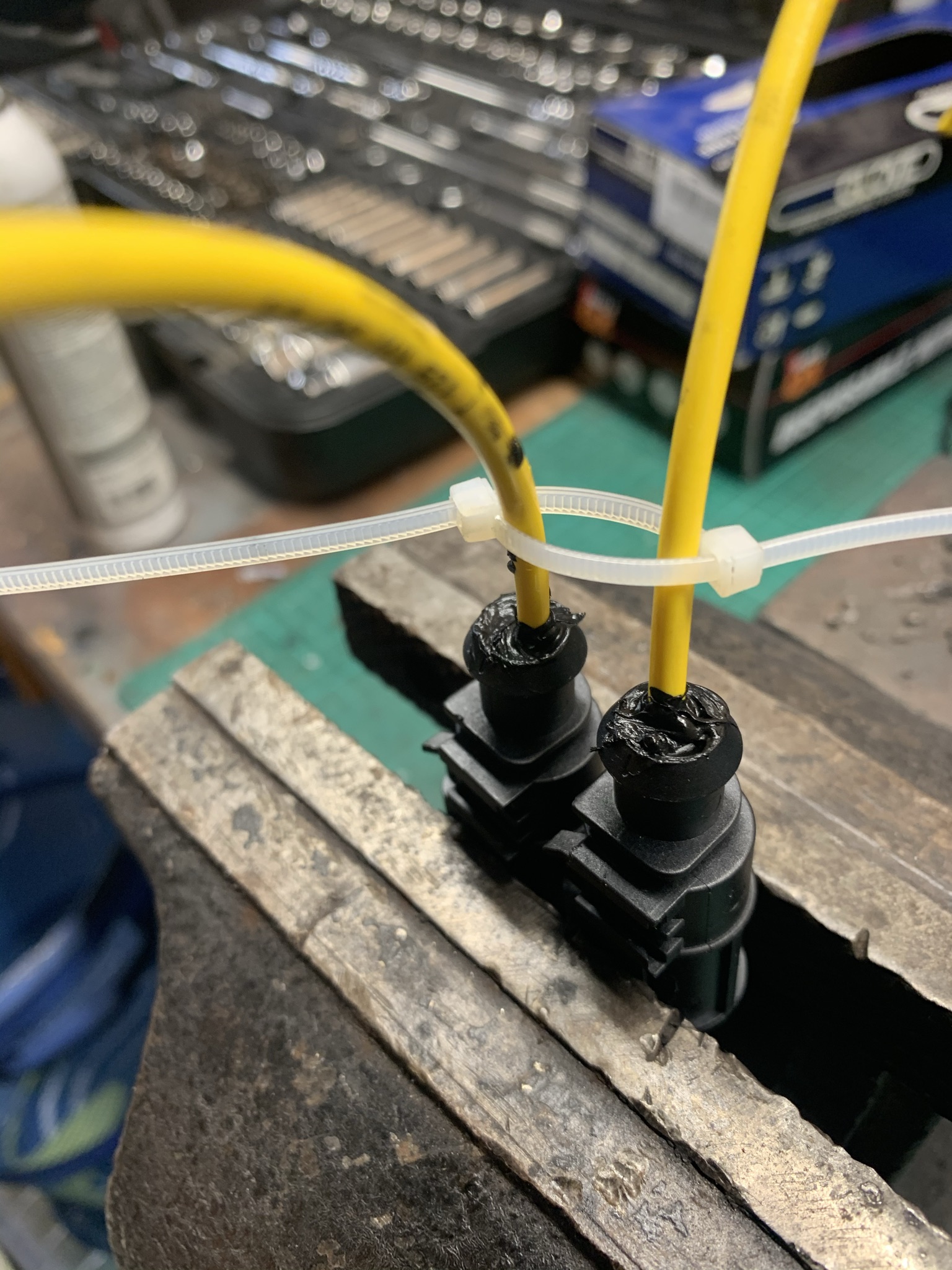
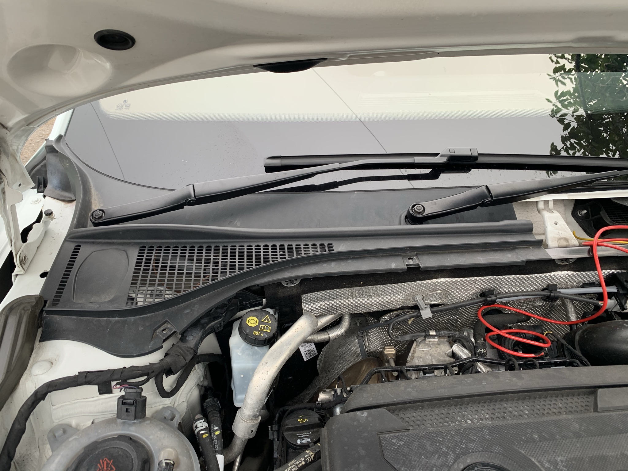
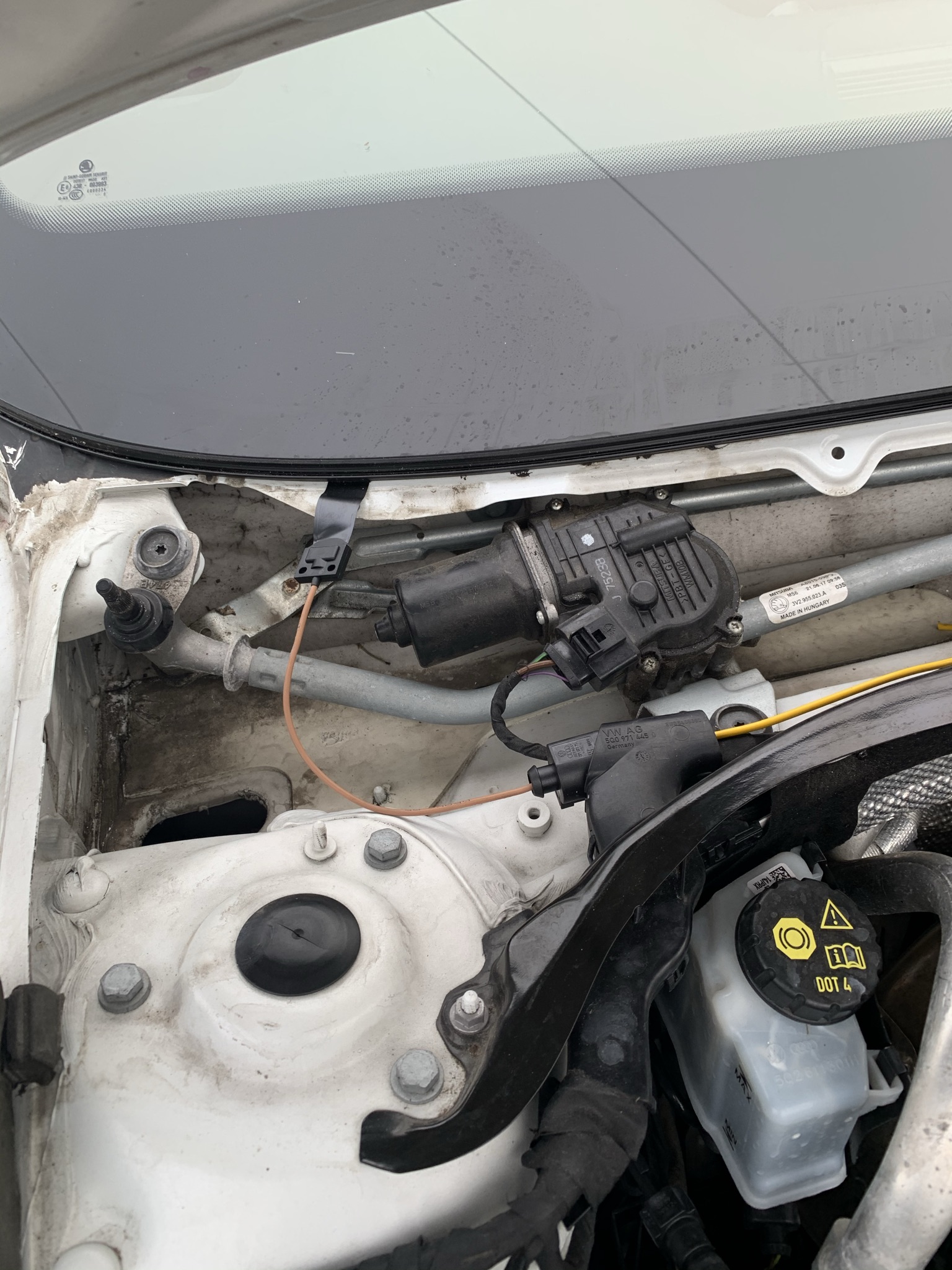
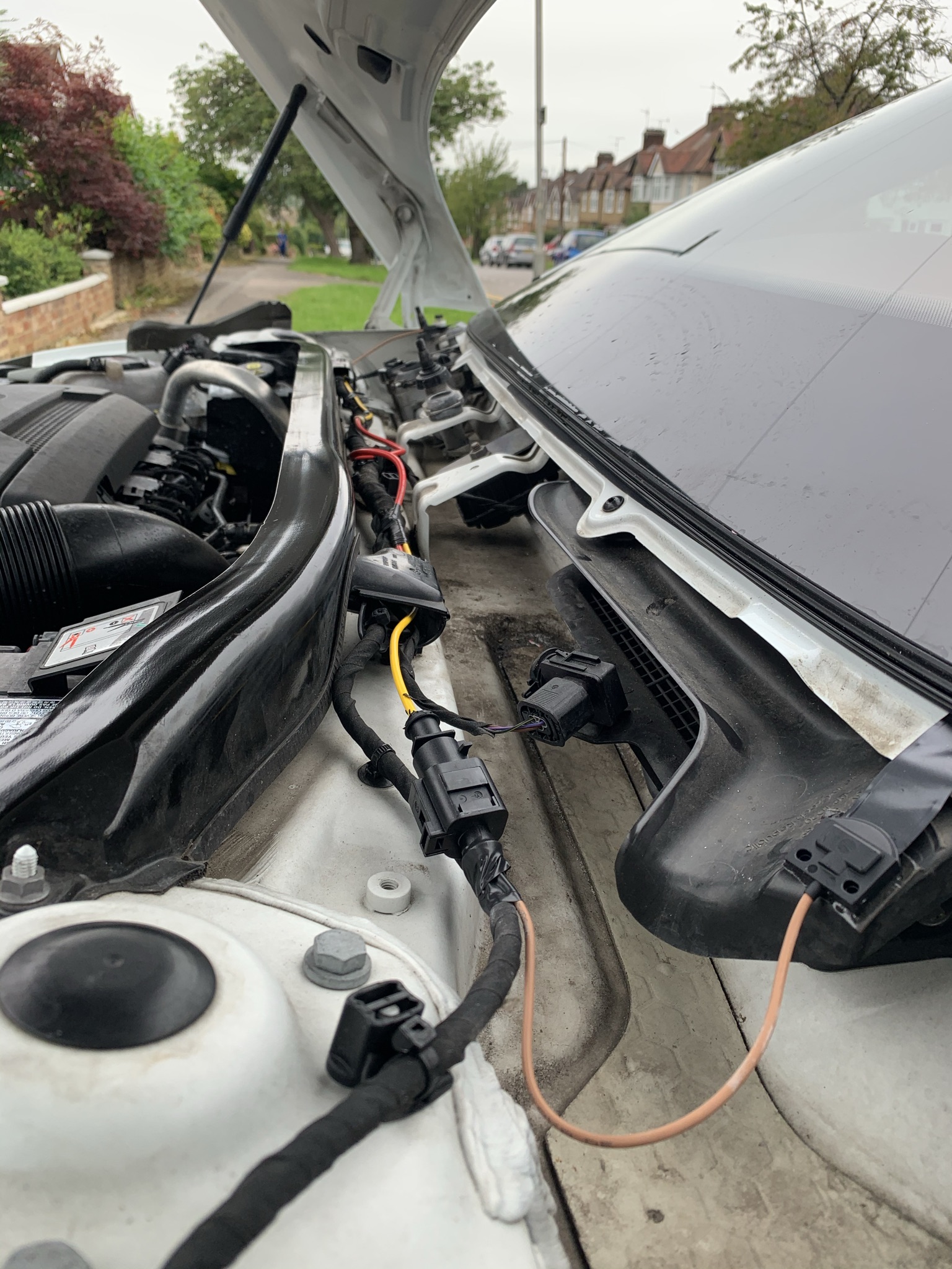
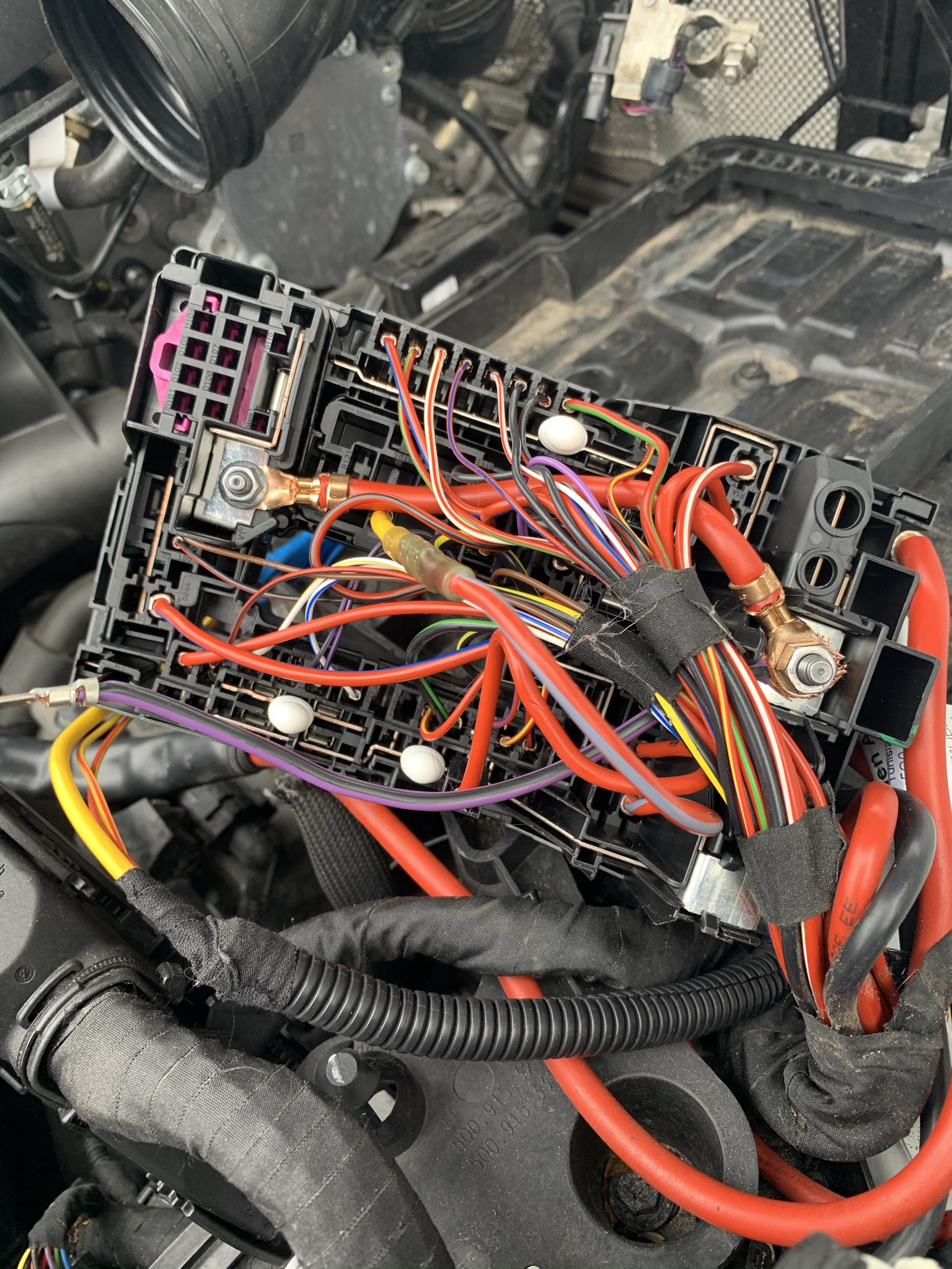
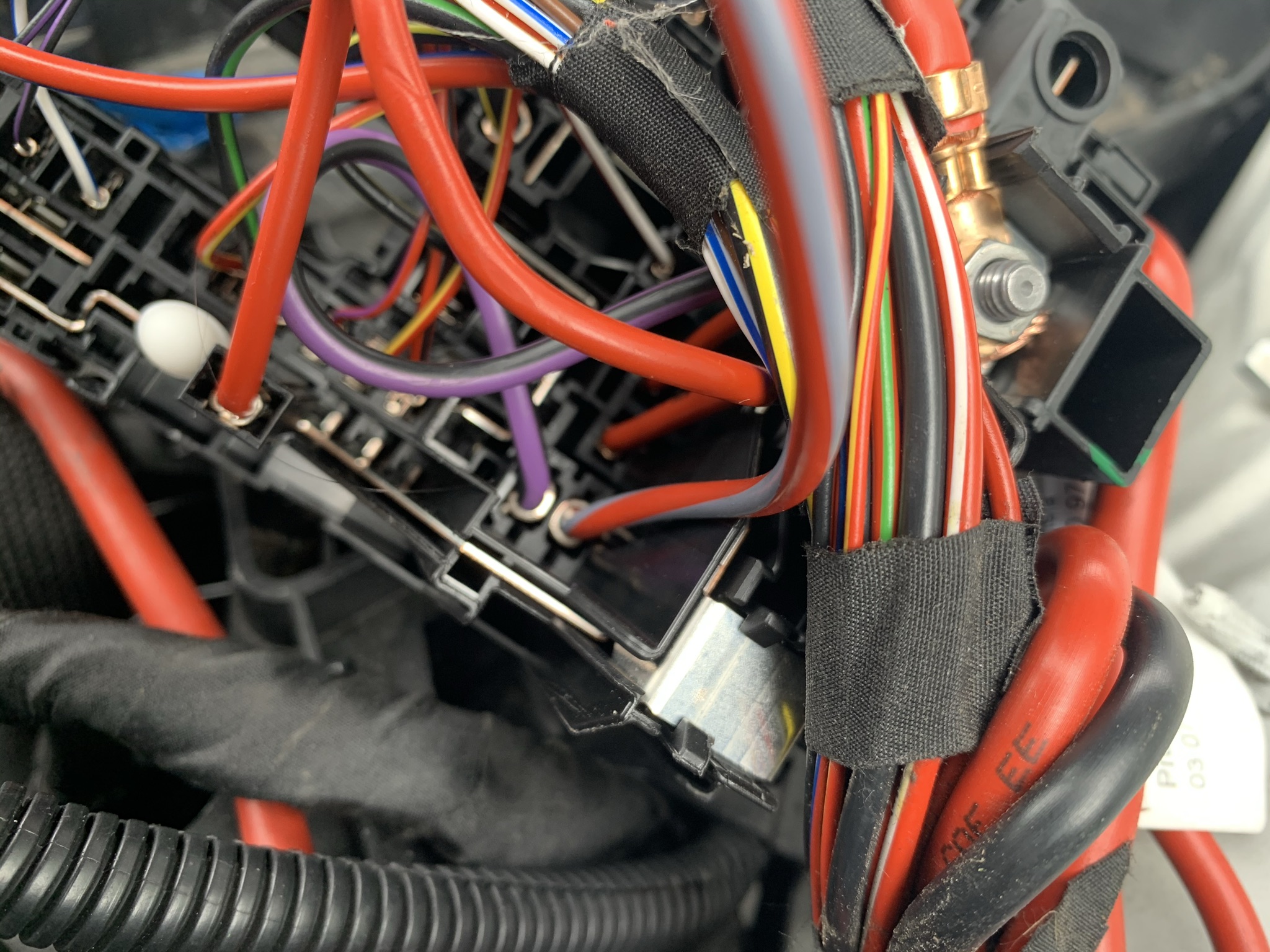
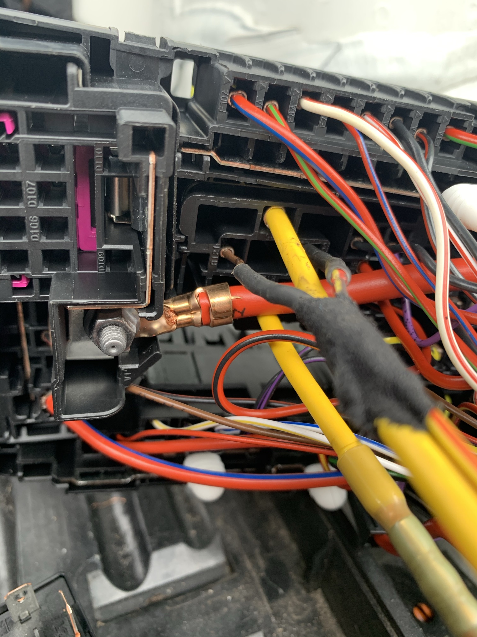
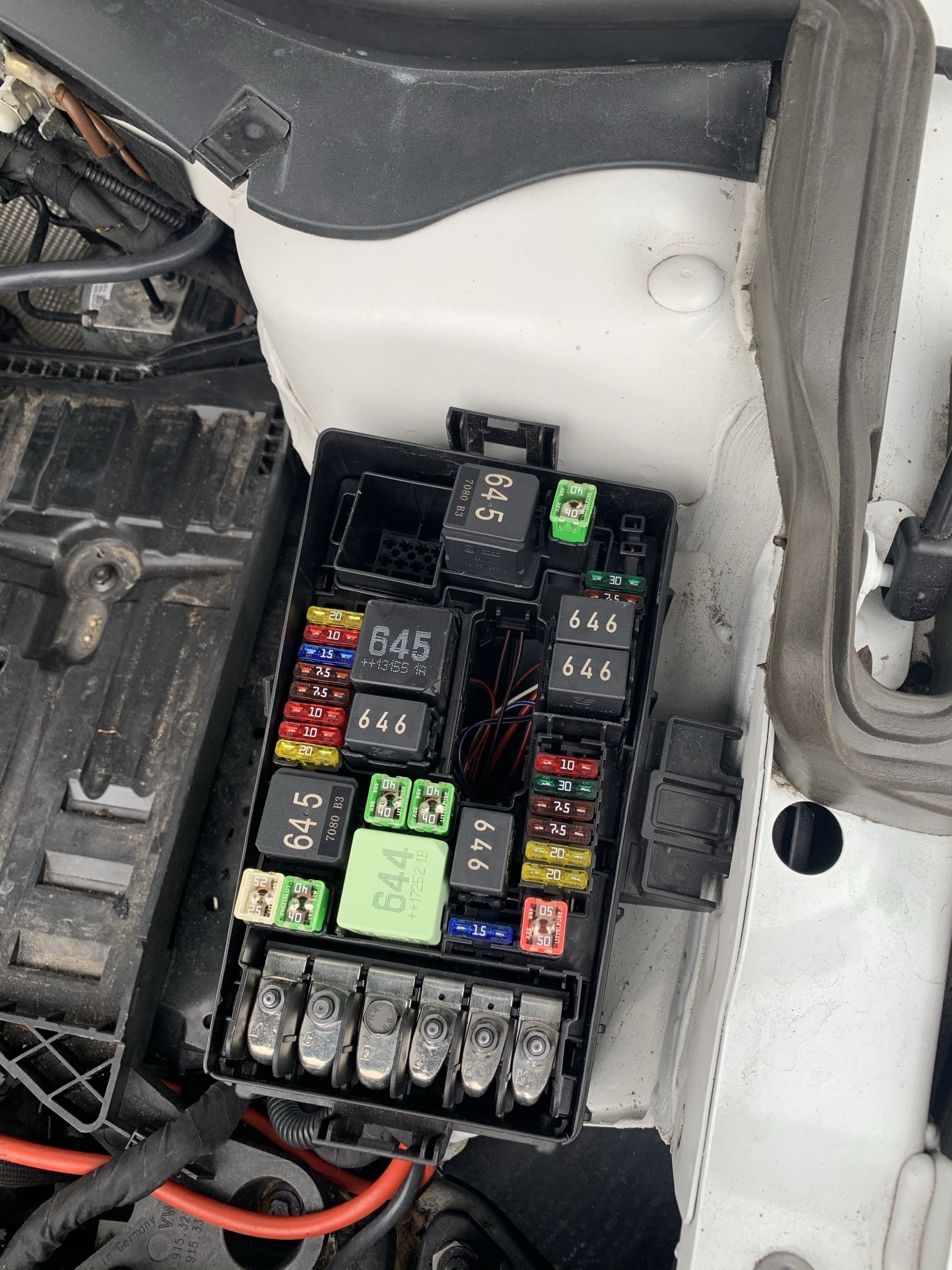
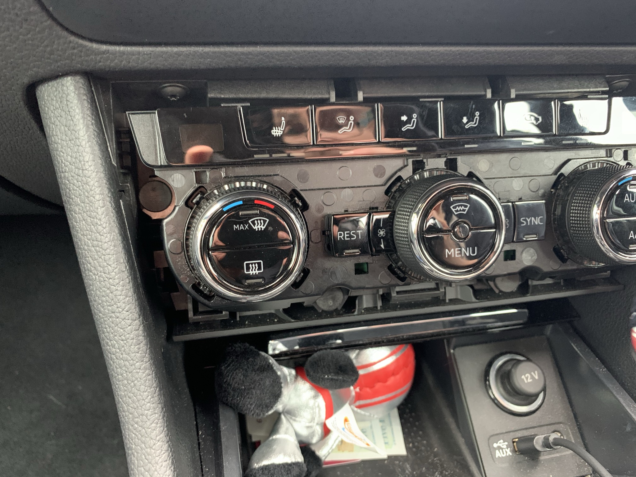
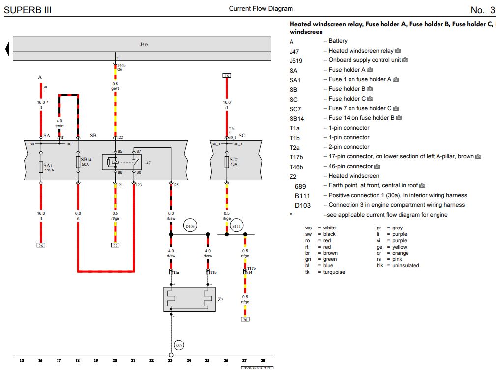
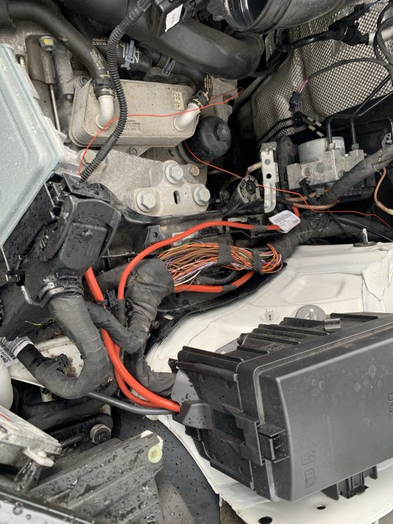
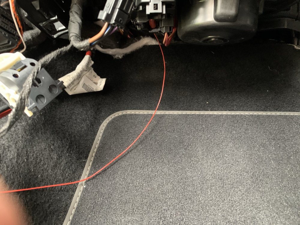
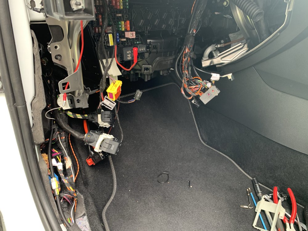
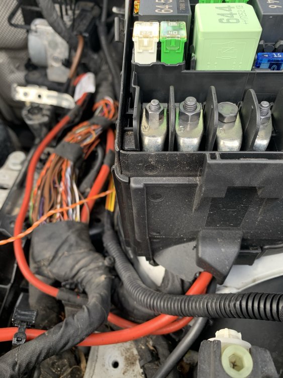
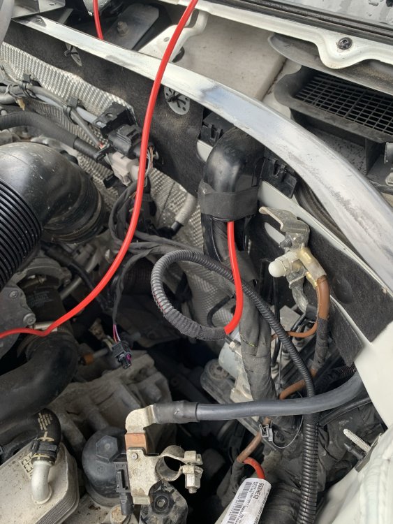
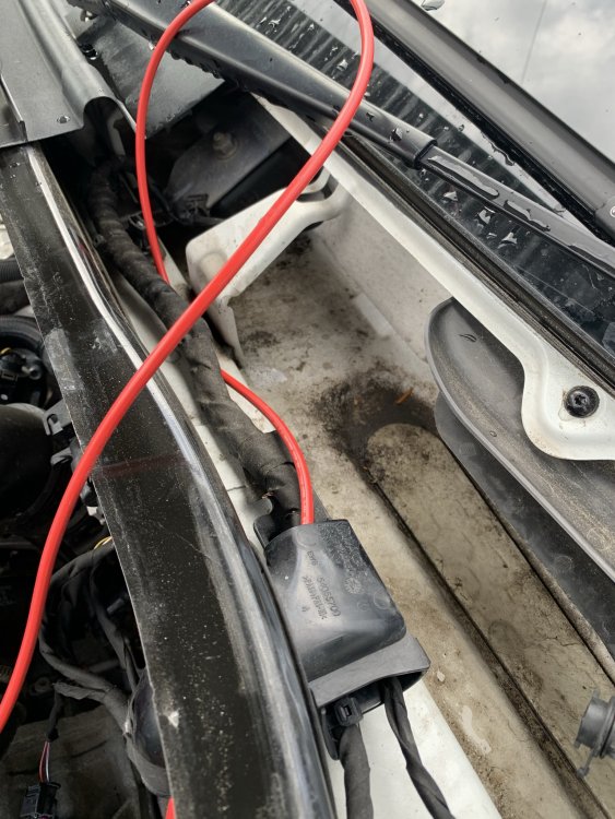
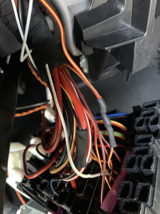
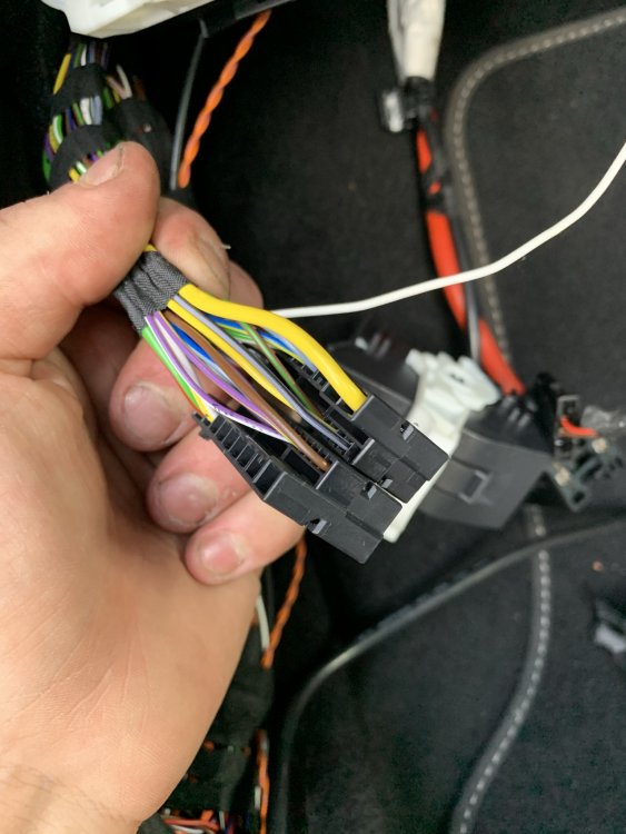
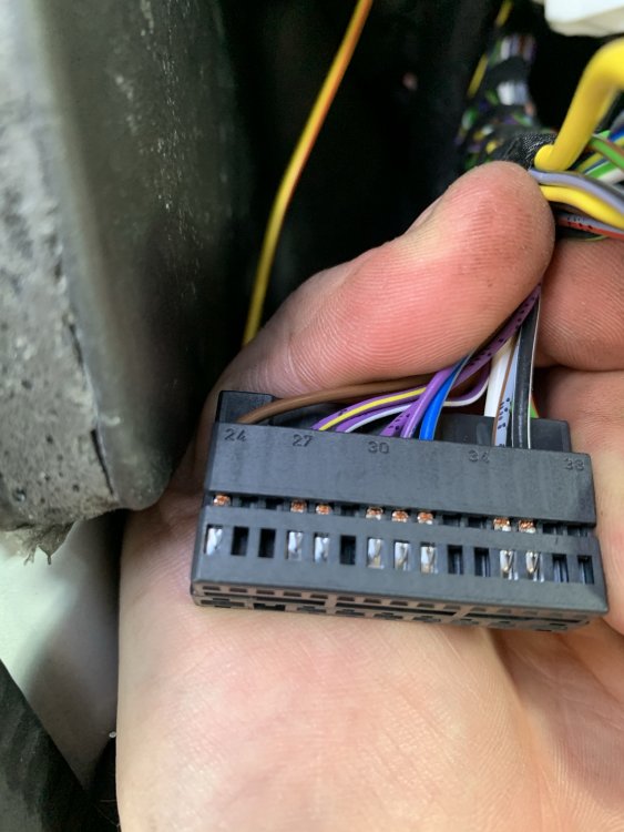
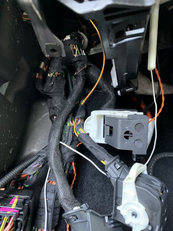
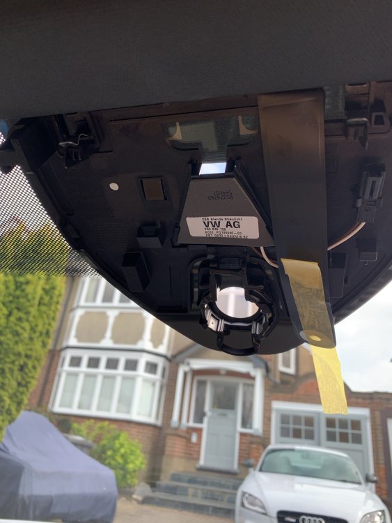
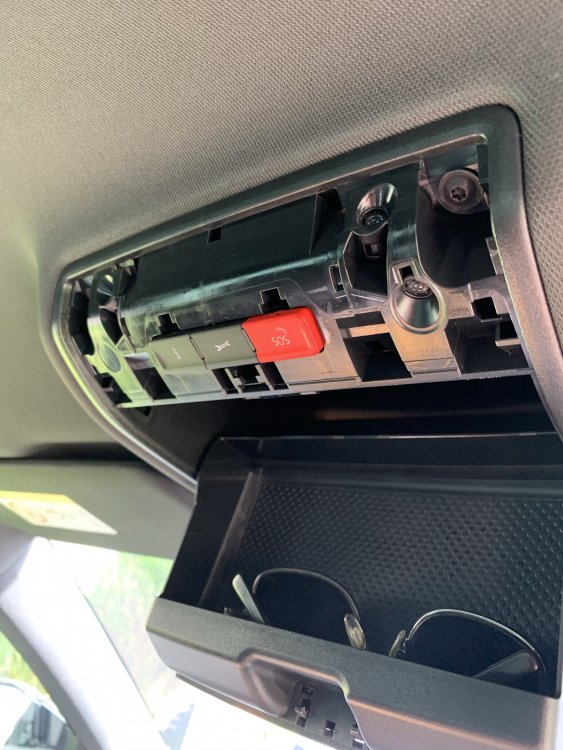
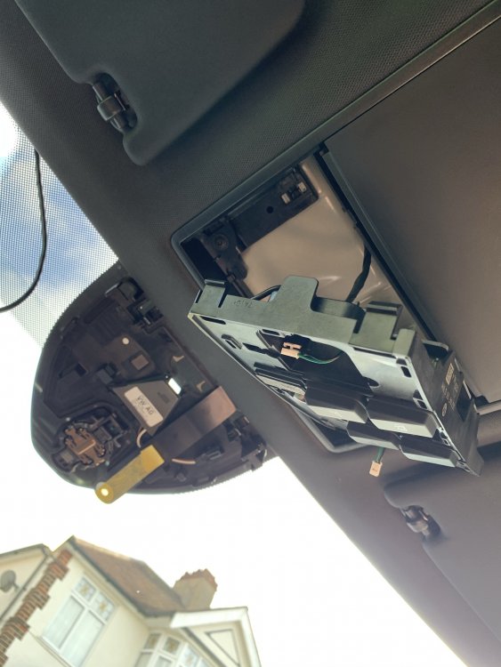
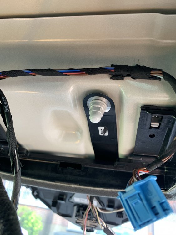
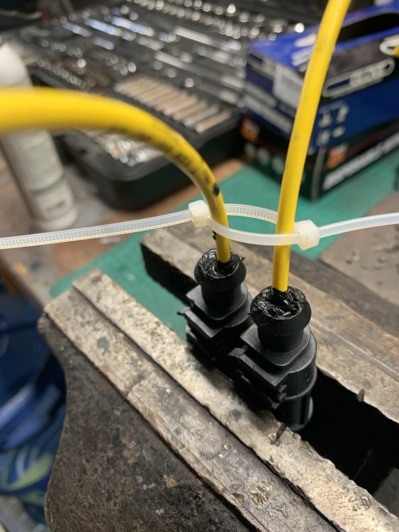
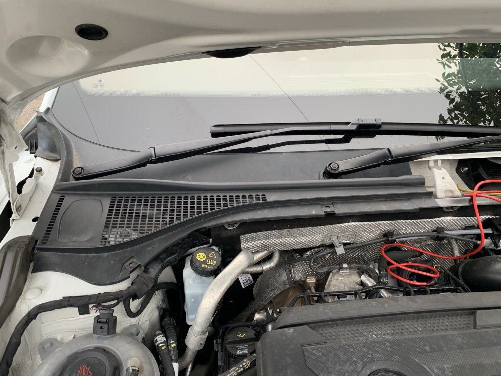
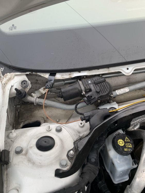
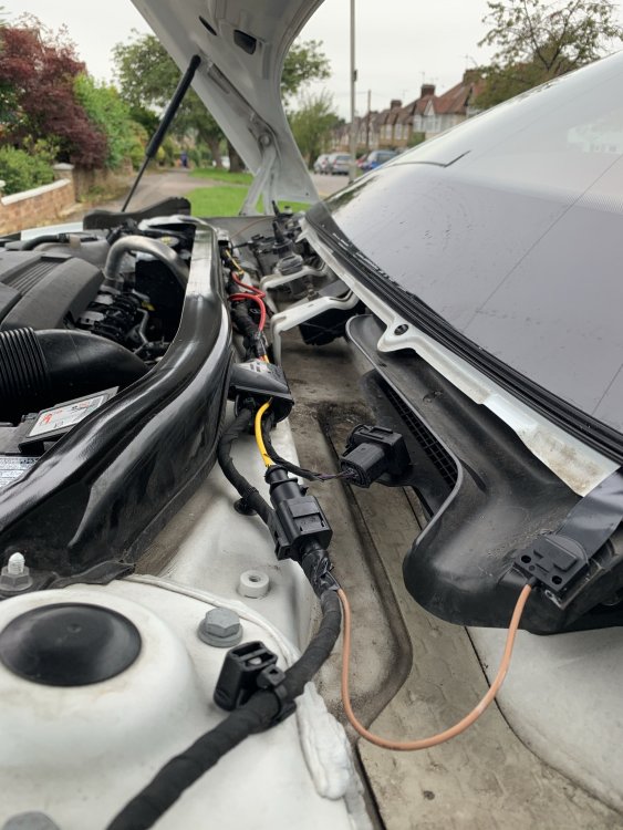
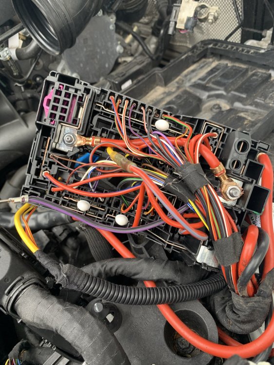
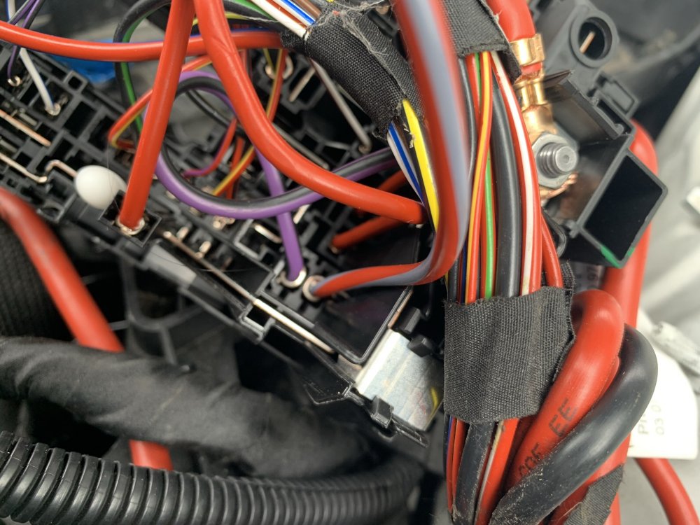
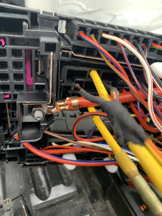
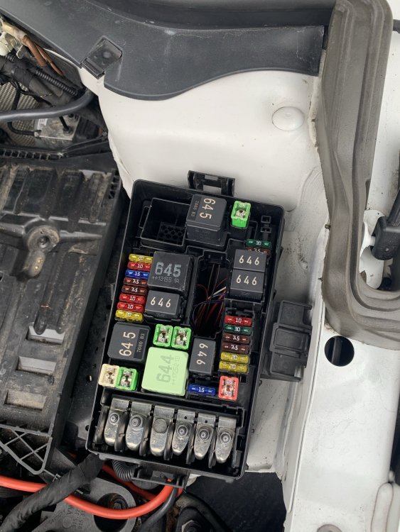
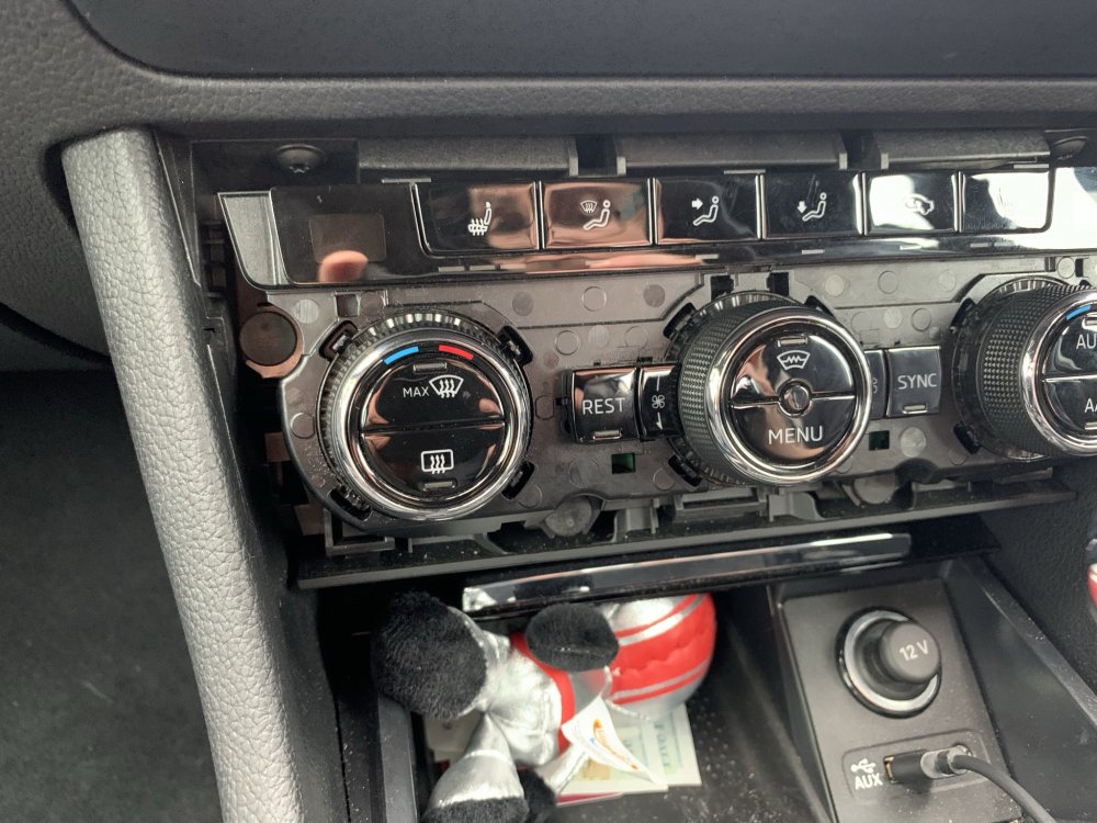
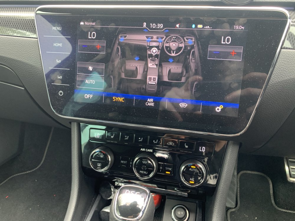
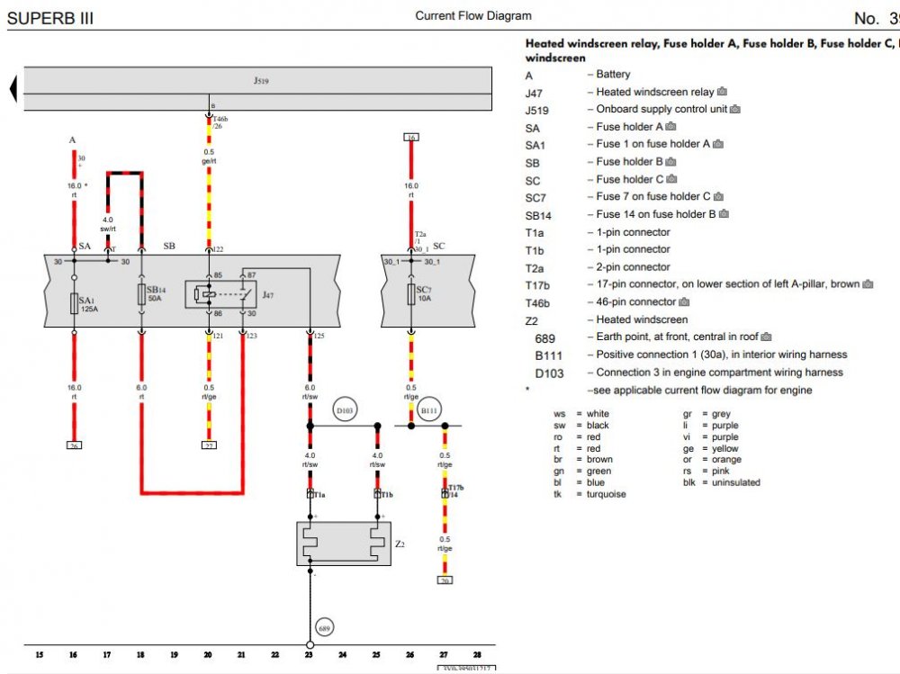
How to: Heated Windscreen Retrofit All of this is done at your own risk and is just meant as a general guide, not a full instruction manual. Just cause some things may work for my car may not mean the same for yours. Parts List 3V0845011AE - Heated Windscreen WITH A5 camera support - Will be different for everyone so confirm it first! 3V0907044DA - Dash Control Panel with heated windscreen button - Will be different for everyone so confirm it first! 071973851 x2 - Large Plug Housing for Heated screen connector 000979307E - Pins for large plug, comes with 2 pins so only order 1 000979425E - Pins for relay with 6mm wire attached, comes with 2 pins 000979027E - Pins for relay with 0.5mm wire attached. comes with 2 pins 4H0951253A - 645 Relay for main current flow 5Q0937507D - Relay holding plate, my car already came with but heres the part number 000979424E - Pins for Jtype fuse in engine bay fuse box with 6mm wire attached, comes with 2 pins N91186305 - 50A Slow blow fuse for heated screen 6mm repair wire - Only required 2 meters to be on the safe side (red) 0.5mm repair wire - Yellow/red repair wire 5m 0.5mm repair wire - Red/yellow repair wire 5m Fuse box terminal - Was not required as it splices into already used OEM pin for climate control 000979009E - Small pin for BCM plug with wire attached Varied Conduit - For wrapping the under bonnet looms to give an OEM feel and protect them Loom tape - for wrapping wiring and securing inside and outside cabin Heat shrink crimp connectors - These are genuine repair methods so order both 1mm and 6mm versions Silicone - For sealing the exterior connectors You will need VCDS & ODIS for this or equivalents. Once you have your parts together and your screen is fitted you will have 3 additional connections, 1 in the headliner, 2 at the base of the windscreen. Wiring Diagram For anyone that fancies going alone and doing the wiring themselves, here is the only wiring diagram you need. Fitting ground wire To start you'll need to drop the front interior lamp, this is done by opening the sunglasses holder and pulling the trim off around the SOS button and around the interior light buttons. Pull the interior light unit out of the housing and if need be remove the torx screws to drop the entire assembly out of the way. Here you will see the 10mm ground stud with a nut on it, remove the nut and fit your ground strap before tightening back up - DONT go crazy as it will tear the strap. Run wires through bulkhead You'll now need to run your 2x 0.5mm wires through the bulkhead, this can be fiddly so a coat hanger of some kind makes the job a lot easier, to start, remove the battery and battery tray to expose the main wiring loom which will be under a plastic cover and disapear into the passenger rear most corner of the bulkhead, the best way to do this is to poke a small hole from the outside in with the coat hanger, then from inside the car, go up under the glovebox and behind the blower motor, you will just see the end of the hanger, attach a wire to it and pull it back through. It might take a few tries to get right and just make sure you don't tear the boot or damage other wires. These 2 wires will be going from the interior fuse box area to the under bonnet fuse box so run them either inside the original loom or use some small conduit to keep them protected under the bonnet from road grime and heat. Whilst you are here, get your 6mm red wire and run it from the under bonnet fuse box area, through the plastic casing under the battery, then up the loom which heads into the scuttle panel area. Again, protect this wire with conduit or run it inside the original loom. Wire up windscreen power supply Now you have the large 6mm wire in the scuttle area, you need to remove the wiper arms which is done with 2x 13mm nuts under plastic covers, once the nuts are off, gently press on the pivot point of the wiper arm to release the entire arm making sure not to damage the screen. There are 4/5 metal clips holding the plastic scuttle covers down, these just pull off. Then starting at the outer most edge of the screen where it meets the plastic, slowly lift to remove all the plastic covers. Do this on both sides to fully expose the lower screen/scuttle area. You should now see your 2 large connectors with brown wires running into the windscreen. You will need to run your 6mm wire to both of these. You may choose a different method but mine was; place the 4mm wire with male pins inside the connector and push the purple tab inside the connector across till it clicks, I then placed the connectors in a vice and filled the rear with silicone to prevent any water getting in. The yellow wire was then cut in half. I ran the red wire all the way to the drivers side of the screen and used a OEM crimp connector to attach the 4mm wire to the 6mm wire. For the passenger side, I cut some of the insulation off the red 6mm wire near the passenger side and soldered the wires together. You will need a big soldering iron for this as the wires are massive. Both connections should be water tight. Secure the new wiring to the original loom and play close attention to making sure the drivers side connector will not make contact with the wiper motor as this will rip the wiring apart. Also make sure the connectors are not sitting in the lower section of the scuttle panel as this gets full of water, the flat part of the connectors should not be kinked either as it will damage the flat wires. Refit all the plastic trim and wiper arms - Use the dirty marks on the windscreen to line the arms back up, short wiper always goes on the passenger side. Wire up interior fuse box Next we are back inside the car and need to remove the glovebox to access the rear of the fuse box. This is done with around 8 torx screws both under and inside the glovebox, slowly lower the glovebox and make sure to disconnect all plugs. I also disconnect all plugs for the infotainment system and move the glovebox completely out of the way to give yourself more space. Now you should see your 2 wires that came through the bulkhead, we only want the red with yellow trace wire right now. Run it neatly towards the fuse box, pull the fuse box forward using the small plastic tabs giving enough room to access the back of it. At this point remove fuse 7 which is a 10A one. Find the red/yellow wire behind the fuse box that goes into fuse slot 7 it will be on the top row, this is where we want to splice our own red/yellow wire to. Make sure to use heat shrink and solder or OEM crimp connector. Place the fuse box back but DO NOT refit the fuse yet. Wire up body control module This will be our last wire under the glovebox area which is our yellow with red trace wire. You will be able to see the body control module (bcm) on the left hand side of the fuse box, it will look awkward to get to but the trick is, it doesn’t need to be fully removed. Where the lower foot well trim meets the side trim you will want to pull up on the side trim, this means you can tell pull the footwell trim out of its clip and remove it fully, once this is out the way you will see a big group of connectors we don't need any of these but instead, you should be able to see the BCM plugs directly above this group of connectors, 3 big plugs, we want the centre one, once the white locking lever is pulled down, you can pull the connector out of the unit then down a track and it will come out under the BCM area, cut the cable tie on the plug if there is one, press the 2 locking tabs in and release the inside of the plug. You will now want to run the yellow/red wire neatly to the plug you have just stripped down, attach the very small pins wire to the end of the yellow/red wire using solder or an OEM crimp connector. The plug you now have will be numbered for each pin hole, you are looking for pin location 26. Insert your pin into this until you hear a click, put the plug back together, secure your new wire to the loom and refit the plug in the opposite way to what you took apart. Refit all the trim at this point, including the glovebox unit but NOT THE FUSE - if you put the fuse back in with exposed wires under the bonnet you will blow it. Wire Up Under Bonnet Fuse Box You will now have your 3 wires at the under bonnet fuse box, you want to cut the cable tie where the wires run into the fuse box and then remove the inside section of the fuse box, this is fiddly as the little clips around the outside are a very tight fit. Once you are in and you can access the underside of the fuse box. In your parts pile you will need to find your 2 sets of repair terminals, all 4 ends will have the same terminal but 2 will be thick wires, 2 will be thin. Cut these in half so you have 4 individual wires with terminals. Attach the thin wire ones to the red/yellow and yellow/red wire. These need to be inserted into the correct relay points. Refer to the photo below which is the brown wire and yellow/red wire you see in the photo, they can go in either slot. This leaves us with 1 more red wire which runs to the windscreen, crimp one of your last 2 big terminal repair wires to it and insert into the LOWEST yellow wire point you see on the relay. Youre nearly there now! You now need to take your 2 large flat male pins with 6mm wire and you will need to cut this in half, this will leave you with 2 large male connectors and 1 large female connector all with 6mm wires. Join one of the large male and female wires together with a wire length of about 10cm. The female end will need inserting into the top relay connector which is pictured with a yellow wire. The male end will go to the fuse holder, this is shown in my picture with a red wire with grey trace and it shows where it must go, take note it will only go in one way round. The final wire which is 1 last big male terminal will need inserting next to the one you just inserted, this will give you your 2 pins for the fuse. The other end of this wire I placed securely under one of the large nuts with a red wire already attached to it. This is to supply the 12v constant supply required. This is shown pictured as a purple and black wire. Make sure all wire strands are secured and none are left to short out anywhere. At this point you can now insert your 645 relay and your 50A fuse. Put all the fuse box back together making sure no wires get caught anywhere, refit all trim, battery and everything else you took apart. You can NOW fit the 10A fuse back inside the car by just dropping the glovebox down, release the hinge on the side and with the 2 clips inside it it will lower to access the fuse board fully. That is all the wiring done! Only 2 more things to do now. Change display unit At this point you should have your new climatronics panel with the heated windscreen button. If you couldn't work out which one you needed, drop me a message. The key is 4GW = Heated front screen. First you will want to connect your VCDS to the car and SAVE YOUR CURRENT LONG CODING for module 08. If you don't do this, you'll run into trouble. Now remove the old unit, pull the plastic trim from underneath to remove it, then do the same with the actual unit no screws, just clips, remove the 3 connectors on the back and fit your new unit in the reverse order. You will notice that you cant turn the fan on or do anything with the heating yet. Don’t panic. Coding Once this is all done you can relax and just do the coding side of things now. Connect ODIS/VCDS to the vehicle and run the basic settings on the unit, this will teach the new unit your heater flap positions. Now put your old long coding back into the unit to save time and make sure everything is how it should be. You now want to open the long coding to make your modifications as follows: Byte 5 bit 0-3: 04 Windshield Glass A/C Comfort Glass [PR-4GW] Byte 11 bit 0: Windshield Defogger/Heater installed [PR-4GW] At this point, clear codes, turn the car off and lock it up for 15 minutes to allow the car to reset the canbus network. Get in, start the car and just confirm the heater is all working again as it should be. The windshield heater will not turn on but the button will flash at this point when pressed. Go to module 09 which is your BCM, Enable security access and go to your adaptations, you are looking for IDE04927-ENG142021-Window heater-Heizbare_Frontscheibe this needs to be changed from Not installed to installed. And that is it. You are all done, heated windscreen fully working. Some of you may notice the empty ADAS A5 camera spot, hopefully another guide for that will be coming in the near future as i fit it all up. Any issues with the guide or comments, let me know.



 1 point









.thumb.jpg.f83a46b9b3c0d976b9dbffbb523c9874.jpg)