


Leaderboard
.thumb.jpg.9dd3f612ba7f13d10be5c518d3c8d255.jpg)


Popular Content
Showing content with the highest reputation on 16/11/20 in Posts
-
4 points
-
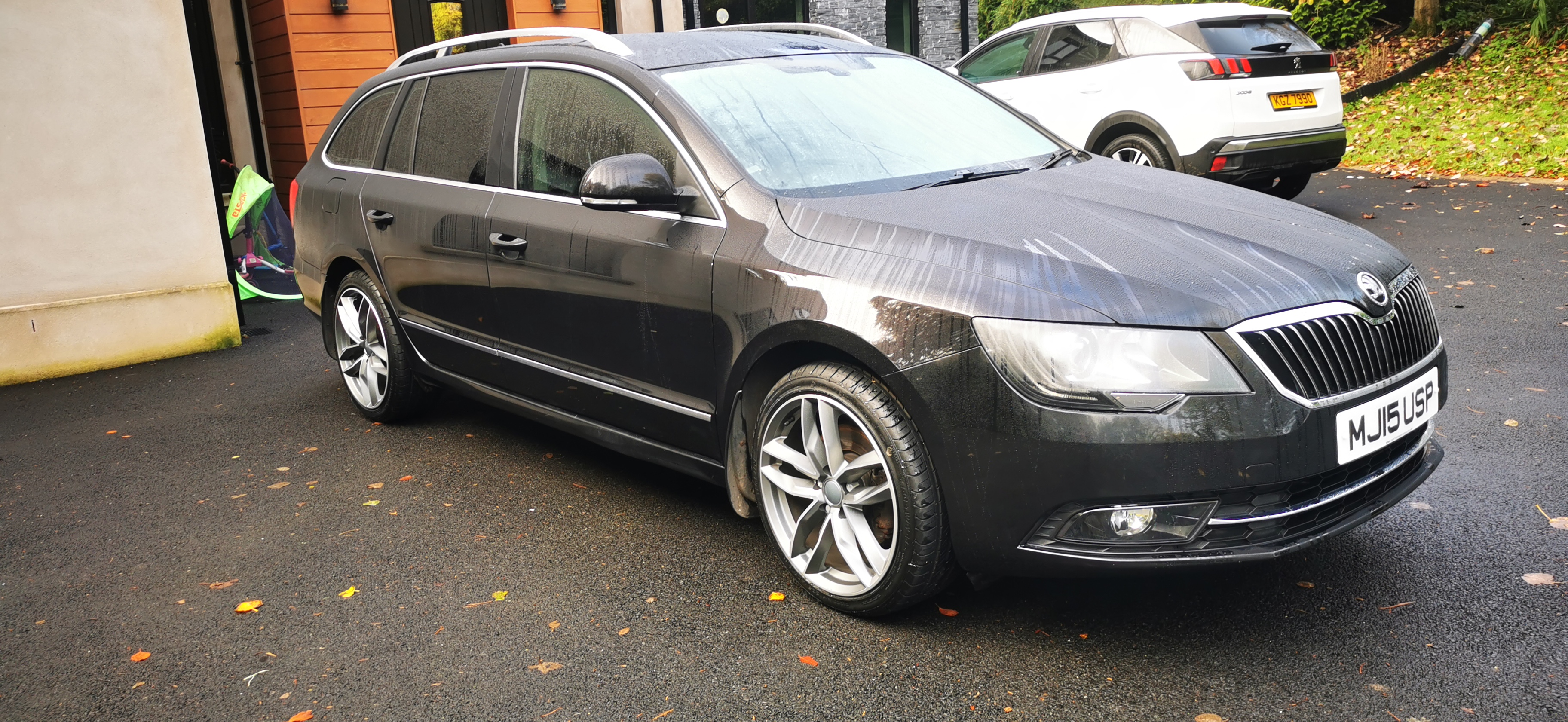
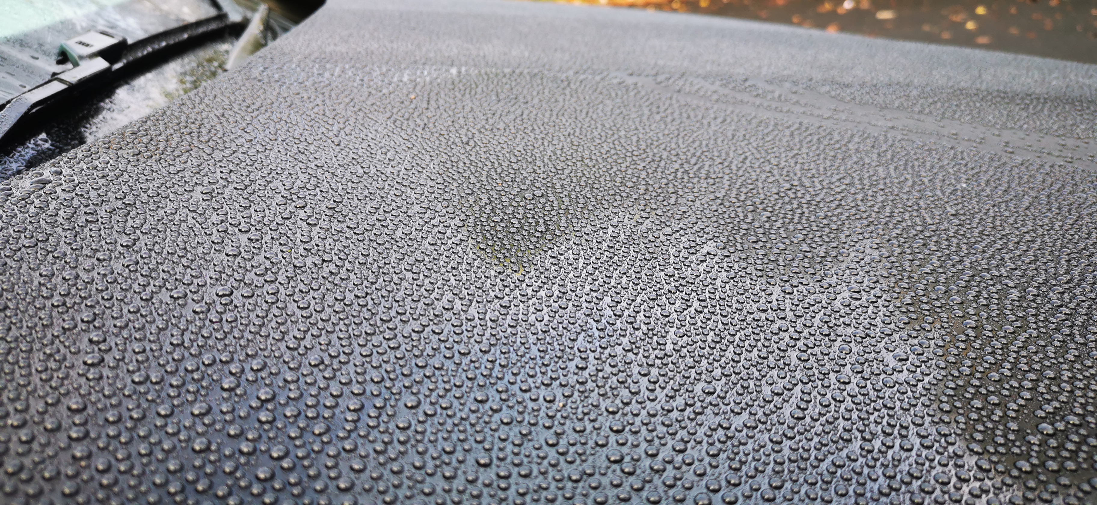
3 points3 points3 pointsFirst time owning a skoda from the usual Audi or bmw estates. My bmw was a bag of spanners and I just wanted rid it was a never ending problem of repairs. I've only had my superb for about 2 months and I love it. Ticks all the boxes I am waiting on lowering ebaich 30mm springs to arrive just to take the harsh look of it being on stilts off and a detachable towbar to be fitted and I will probably be done tinkering with the car..... Unless anyone else has any suggestions Well I got to do what I love to do and clean the car just to get rid of as much of the surface issues on the paint. A night going over it with the da polisher and sealing with some bild hamber wax adds some great hydrophobic ability


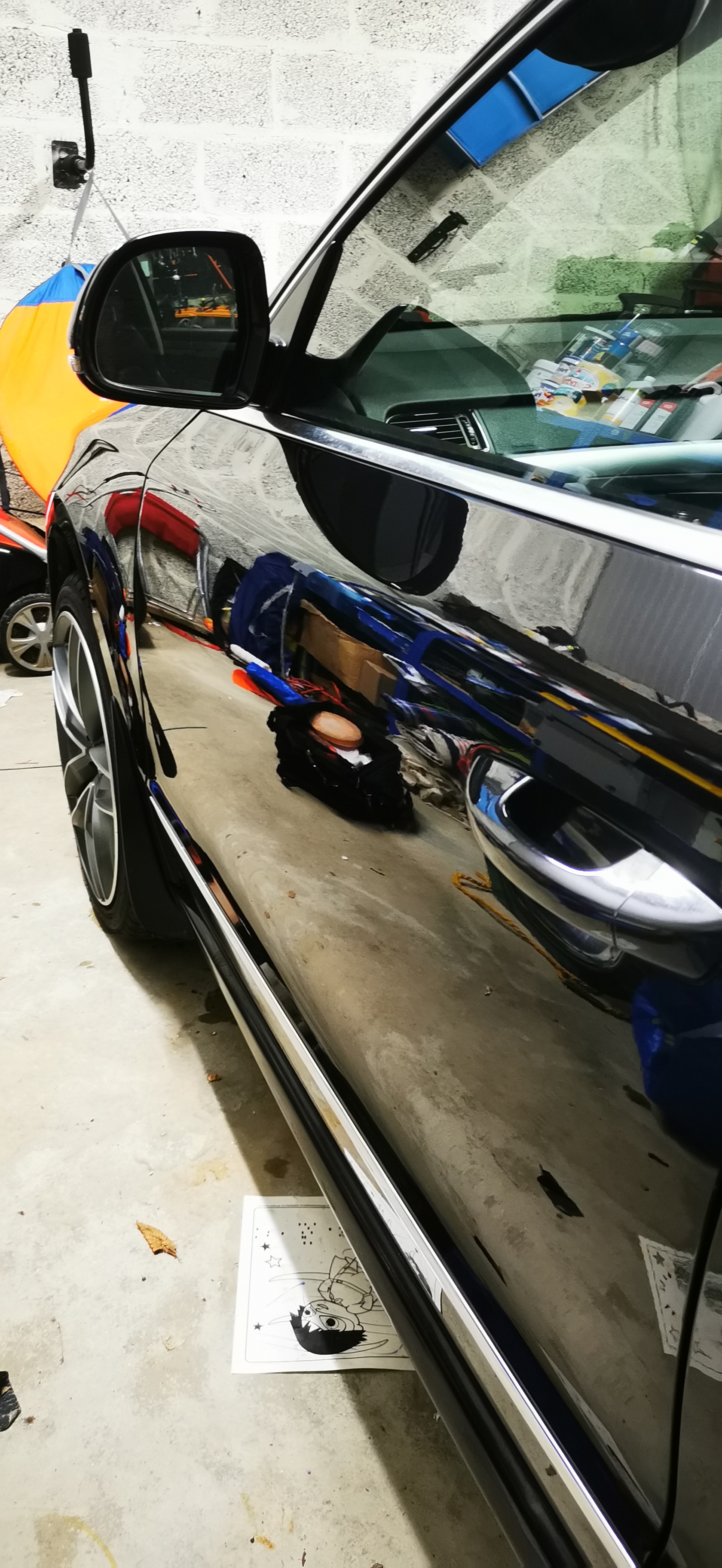
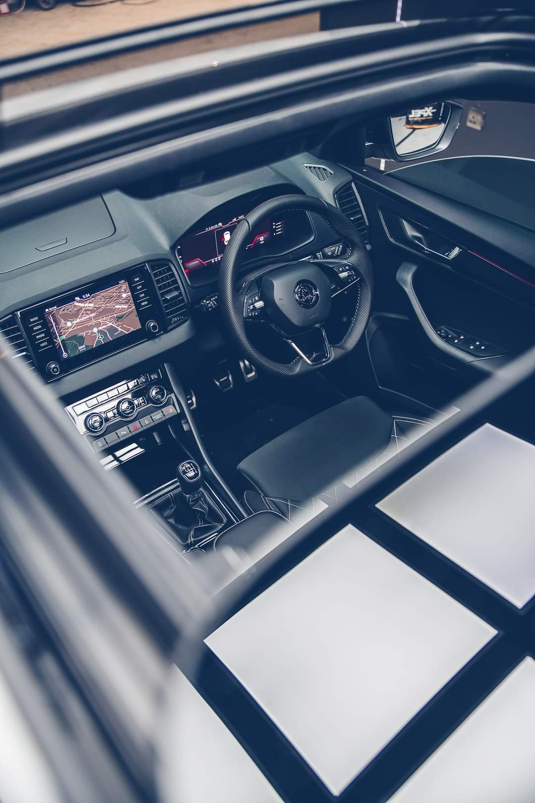
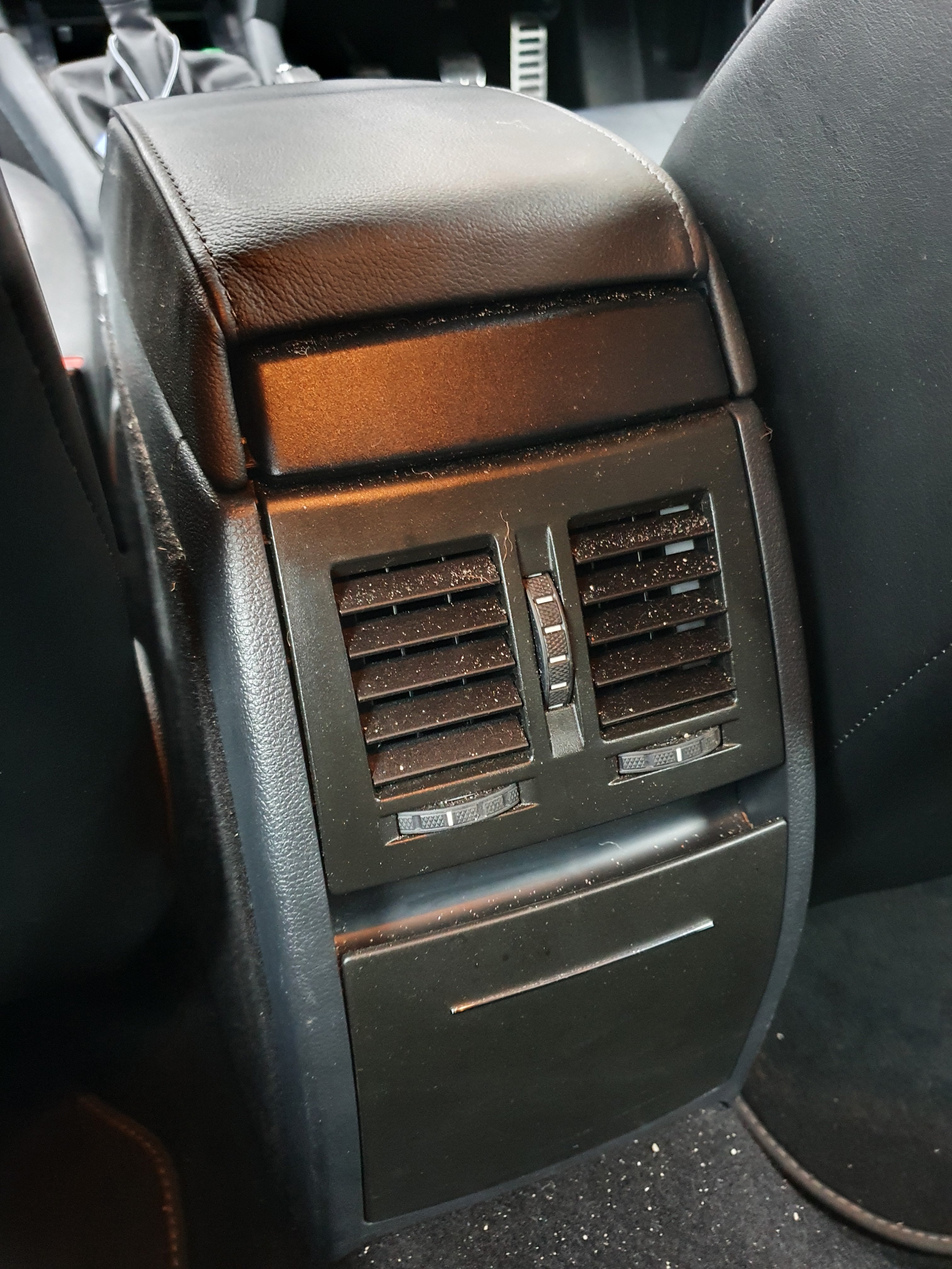
 3 points3 pointsHoping this will help with the old car smell ! A bit of extra lowering with 140kg of builder's mix in the boot Also, some nice cars at cars and coffee yesterday.3 points2 pointsYes there is! You will need to go to a car parts outlet and look for some a/c disinfectant spray. I did mine a couple of weeks ago for about 6Euros. basically you set the a/c on full and set the disinfectant 'bomb' off and close the door. takes about ten mins to work it's way around the system. job done!2 points2 pointsHaving the PPF applied. No badge on the car as I was waiting from one from SuperSkoda
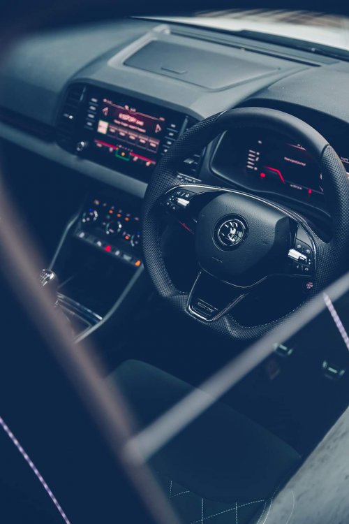

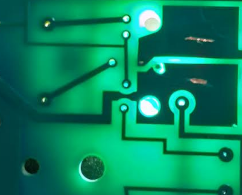
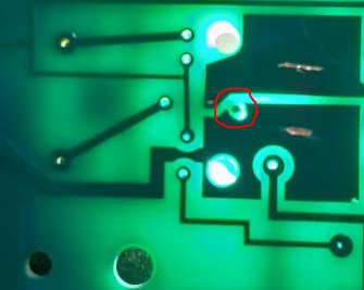
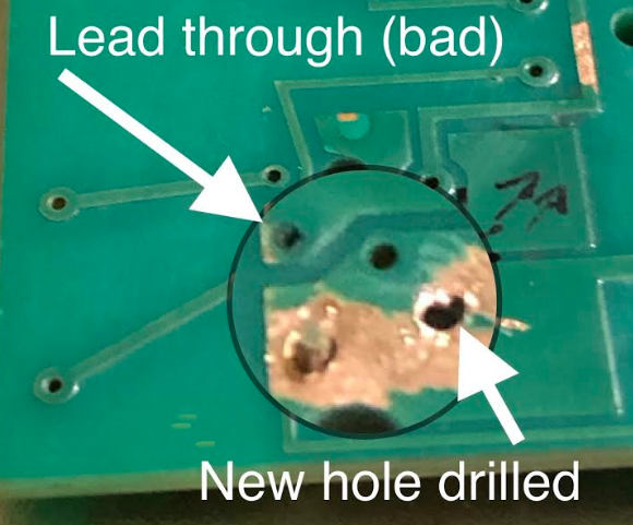
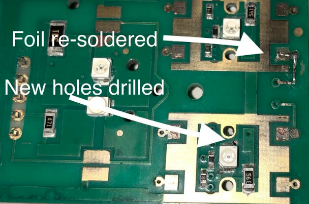
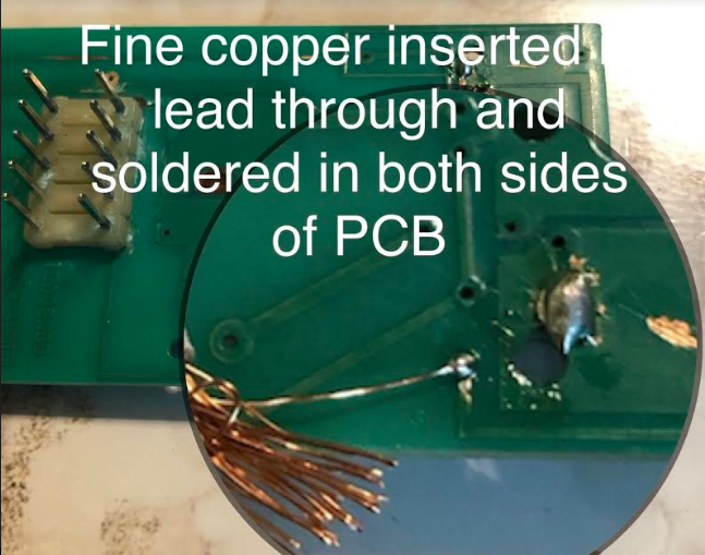
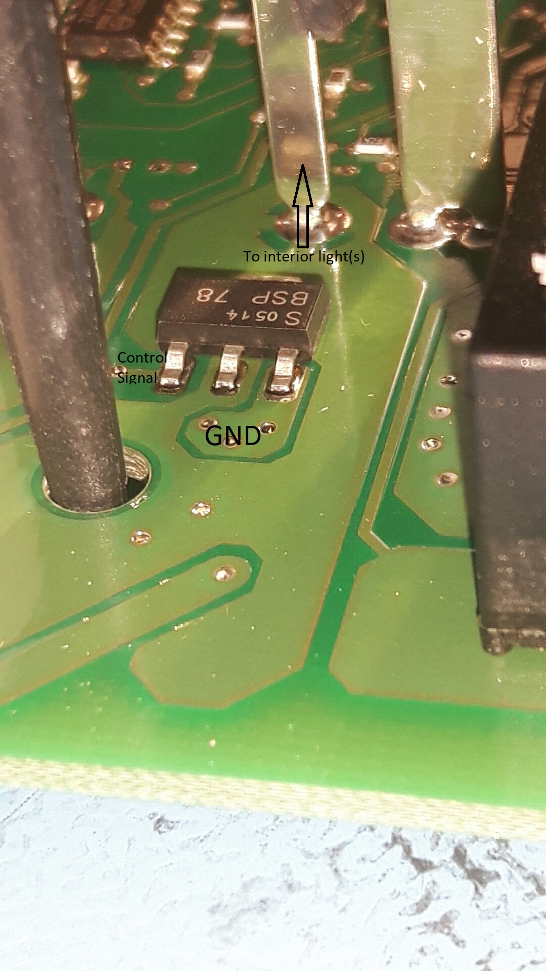
 2 points1 pointSo after sticking 8.5kg of sound mat throughout my boot, bonnet, wheel arches, mud guards, underbody protection panels and skid pan in an effort to reduce road noise on Australian coarse chip surfaces I was a bit down hearted, the road noise had gone from being impossible to live with to a much better, less harsh, boominess. Better but not as good as I had hoped. So today I changed the wheels and tyres from 225/40r18 (7.5") to 225/50r17 I got an excellent deal on the 17" wheels from a 2020 Octavia buyer - 17x7" for AU$200 (EURO140-ish) - and went up from the recommended 215/50 to 225/50 (the VW Passat uses this size as standard) This was my last throw of the dice. First impression is "OMG!!!! HOW BLOODY GOOD!!!!": I am yet to do some Australian coarse chip freeway running, but on a couple of local roads the difference is incredible. I should have started with this change. It is soaking up the road imperfections with a soft bump, rather than a hard knock. And the while there is still a rumble on the coarse chip it seems much more muted. Only a true Highway run on the coarse stuff will show the worst. I'm very, very happy. The sound mat will also be helping no doubt, so no regret in the time and effort spent. I'll update when I have done a freeway run. I have 650km to drive tomorrow. Not dreading it now.1 point1 pointHi, My Octavia Electric Window switches were faulty. There was no back lighting on any of the switches, the passenger side did not have down or one shot down and the driver side up was intermittent. The rear windows were fine for up down and one shot function. The rear window child lock did not operate, but it had back lighting. I decided to open it up to see if it could be repaired. Getting it apart is quite tricky as the latches that hold the unit together are very tight. I used some butter knives inserted along the sides to release the latches, but there is a risk of damaging the latches permanently. Once you have released all the latches on one side, you can move to the other latches and hopefully, this will allow the switch unit to pop apart. Once open, the corrosion was evident. Some of the "lead through" holes in the PCB were corroded and therefore open circuit. In the picture above, the large copper areas are directly under the back lighting LED for each switch, and each area had a lead through, which was open circuit. In total, there were 7 lead through connections for the back lighting which were open circuit. I also found 4 bad lead through connections for the passenger switch functions which needed new wires fitting. In order to fix the connection, I drilled a 0.7mm hole though through the PCB next to each back light LED, so that the hole would connect the copper tracks on both sides of the PCB. I then inserted a single strand of 0.1mm copper wire (a single strand from a flexible cable) in the hole and soldered it on each side of the PC to re-make a new lead through. You have to ensure that the wires are kept a s close to the LED's as possible, as they could interfere with the tactile switch frame that sits on the PCB. This was a difficult job and I am not proud of the quality, but it serves its purpose. The rear window OFF button uses conductive rubber pads to bridge two copper tracks. This function was restored by cleaning the PCB with a fibreglass pencil and cleaning the conductive rubber with some isopropyl alcohol (tape head cleaner fluid or vodka at a push!). The layout of the connections to the connector are: Pin 1 - Rear Windows Lock Off (command to ECU) Pin 2 - Rear Windows Lock ON (Orange LED) Pin 3 - 12V for Backlighting for all switches (Green LED's) Pin 4 - Ground (0V) Pin 5 - Front Left Window Pin 6 - Front Right Window Pin 7 - Rear Right Window Pin 8 - Rear Left Window Pin 9 - Not used Pin 10 - Not used The four functions of each switch (UP, one shot UP, DOWN & One shot DOWN) are determined by the resistors on the PCB. When a particular resistance is measured by the ECU between the relevant pin for that window and ground, the ECU performs that function. For example, when you press the right front button fully forward, you get One Shot DOWN function, this is because the switch will connect a particular resistor between Pin 6 (Front Right) and Ground. The ECU interprets the resistance and translates this to the required function. I didn't measure what the different resistance were for the four functions per switch. All windows perform their correct functions and all back lights now work. Hope this makes sense Russ
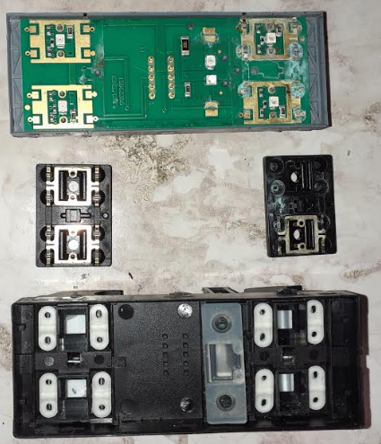
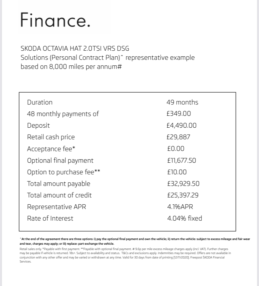
 1 pointIt's a complete wholesale rip-off of the BMW i3: Their interior trim themes are called 'Interior Worlds' and come in 'Loft', 'Lodge' and 'Suite'1 point1 pointFinance example here from Simpsons Skoda for the Hatch petrol DSG. includes £2k contribution from Skoda, a £2,500 customer deposit and a little more discount on top going by the listed “cash price”, all translates to £349 a month for a base car, with an £11,600 GFV over 4 years.
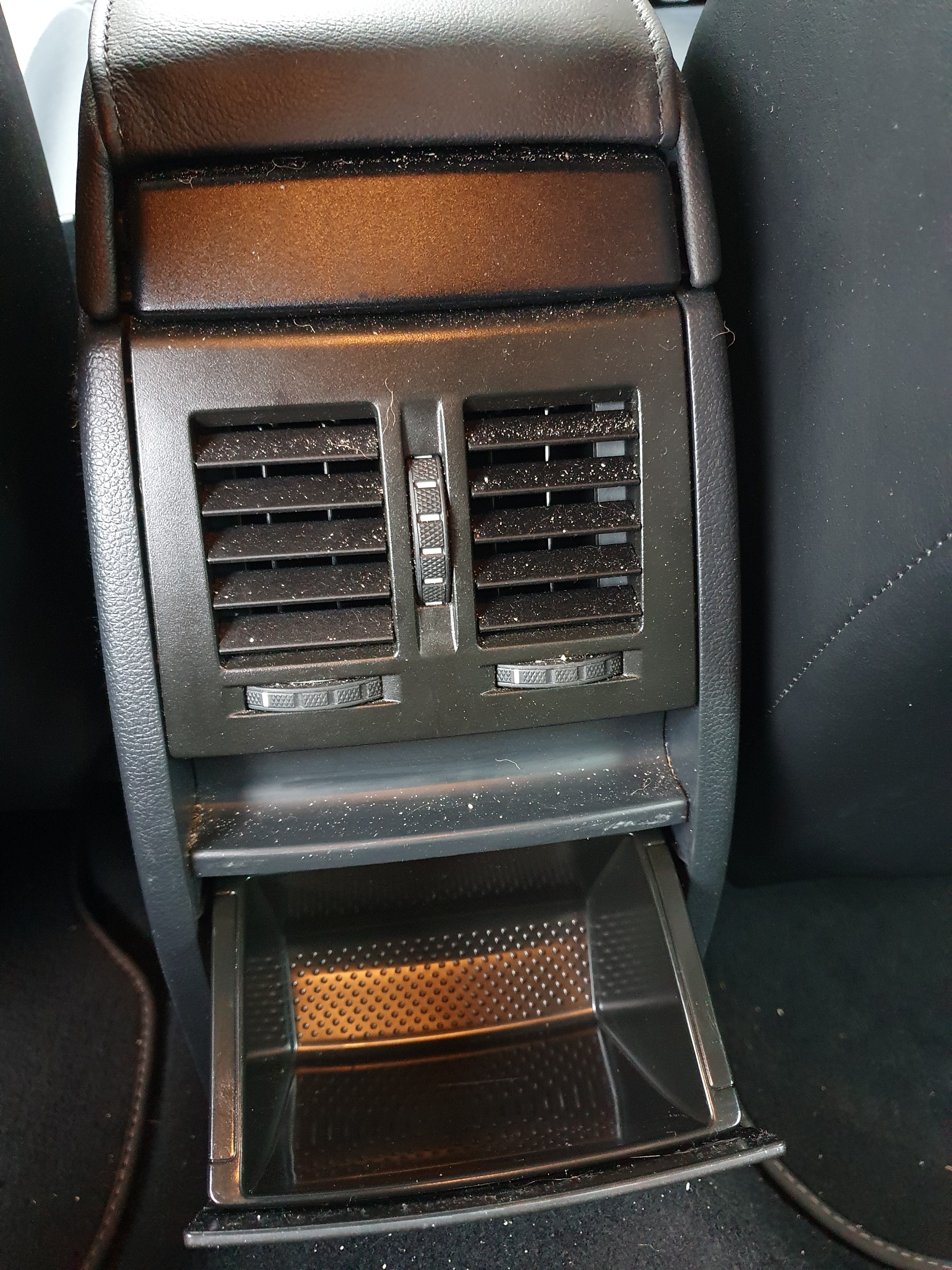
 1 point1 pointIt sounds like something in the clutch pressure plate is acting like a James Watt governor and impeding the plate from re-engaging at high revs. That it's a non standard clutch makes it the primary suspect.1 point1 pointI don't know, it's a bit odd as there's no need to take the pump off, as you say. I wonder if it has to come off on models with A/C. Not sure.1 point1 pointI will get a pic of it once I get it lowered I really just want a factory look maybe slightly more sporty than the river crossing stilts its on atm.. Also anyone that has any interest it's a great company from northern Ireland ( my local) that does car cleaning products they are fantastic and form a great foundation when it comes to cleaning my cars. And when in a rush I just get his hybrid product on after a quick wash works wonders. Sounds like a plug it kinda is as I think he deserves the praise for quality and price https://anachem-automotive.com/ But looking forward to seeing my superb a bit lower. Also anyone any modifications hacks or additions I should be getting? My biggest gripe though is the cup holders are terrible for a travel mug!!!1 point1 point1 pointGuff indeed, its been at least 15 years since VAG vehicles had an old school E/M clutch operated system but it will likely be another 15 years before the guff ceases. I find that leaving the A/C on results in steaming up when restarting the next morning because of the condensation present on the condensor when shut down remaining in the vehicle, it does not take long for the system to clear it but if its not used in the first place it does not happen, any misting will be due to the weather conditions, wet clothing etc. I had a vivid example of it once when returning on the Eurotunnel, I had driven 75 minutes to Folkestone, then maybe another 20 minutes around the terminal before embarquation, A/C was on & all windows clear as they were initially when I restarted after the 35 minute journey, the weather conditions at Calais were the same as at Folkestone but within 2 minutes on the rocade everything was so steamed up that even with vigourous wiping with the chamois the fan would immediately steam them up again, it was so bad that I had to stop.1 point1 pointWith the engine running you set the AC to recirc, then place the 'bomb' inside the car (passenger footwell is often used) then following the instructions on the 'bomb' enable it (i.e. set the bomb off) then LEAVE THE CAR and shut the doors. Then just wait as per the instructions on the bomb before opening the door and safely disposing of the new expired 'bomb'. I've only had to use such a 'bomb' once but it certainly got rid of the musty smell.1 point1 pointIt usually comes in an aerosol can. Turn the engine and A/C on in Recirculate mode, set to come out of the dash flaps and floor (NOT front screen), get out of the car, place canister in the rear (on the transmission tunnel or in the rear centre cup holder, activate, close all doors and remain outside the car while the A/C 'inhales and exhales' the disinfectant or A/C freshener for ~ 10 minutes. If you're in Croatia you may have Sonax or Nigrin products. Either will do.1 point1 pointIt's a usb c port to power a dash cam, (or anything else you want ) that you'd stick near the mirror. Saves trailing wires.1 pointPerhaps Ariel should offer free yoga lessons along with the crazy £77,000 asking price.1 point1 pointI complained to Skoda and you would hope that the complaint would be aggregated by them and then passed on to the mothership (VAG) and then on to the folk who do the work. Unless more people complain to Skoda UK about the issue then they will not see enough complaints about it and I guess do nothing. It wouldn't really be appropriate for me to try and reach out to the middle man. What it needs is more people to fire off emails to Skoda CS about it and that's only going to happen if people are bothered. I did see someone else complain about the french village names and they also complained to Skoda (I think) but the problem is that skoda customer services, when I contacted them, due to perhaps some language issues (or perhaps something else - I could not possibly comment) just don't seem to get the nature of the problem - At least not the people I have communicated with. I got fed up with them as I felt I was "watering in the wind" and getting rather wet with unspeakable liquids. :-) I do most of my shopping at a little place nearby called "Computer Keyboard" at the moment.1 point1 point1 point1 pointWhen I KNEW that there was a software update available for both my Amundsen MIB1 and my engine ECU my then Skoda dealer (I've moVed since) not only refused to apply the updates but even had the cheek to tell me there were no updates1 point1 pointYou could skip the tracking since everything is going back together the same way it came apart.1 point1 pointThose 'rings' sound like shims which you use to get the chainline dead straight between the sprockets.1 pointAh yes, I was wondering if either of these cars were affected by JerkGate thanks for the info, think I’ve made up my mind :)1 pointMet Tiff at Silverstone in 1993 when he was demonstrating how sideways a Nissan Primera GT would go. Dad had a very similar Traveller in the early 1970's which took us down to the IOW on a family summer holiday.1 point1 pointThe interior light 'controlled ground' connection is done by this device, I've just seen: Datasheet here: http://www.farnell.com/datasheets/1651292.pdf Can be just on/off in terms of grounding the low side of the lights, and/or can do fancy stuff like fading out gradually.
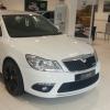
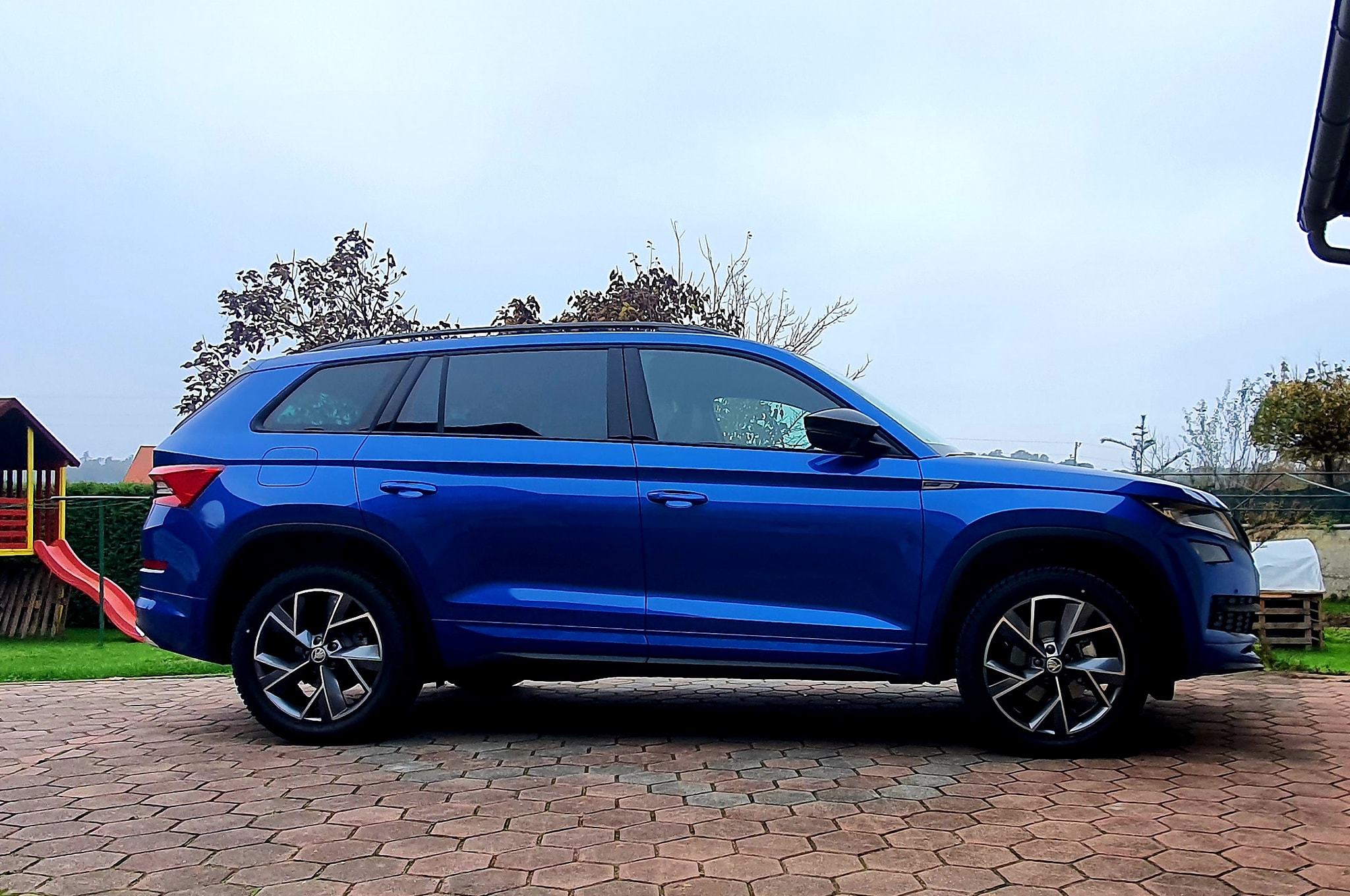
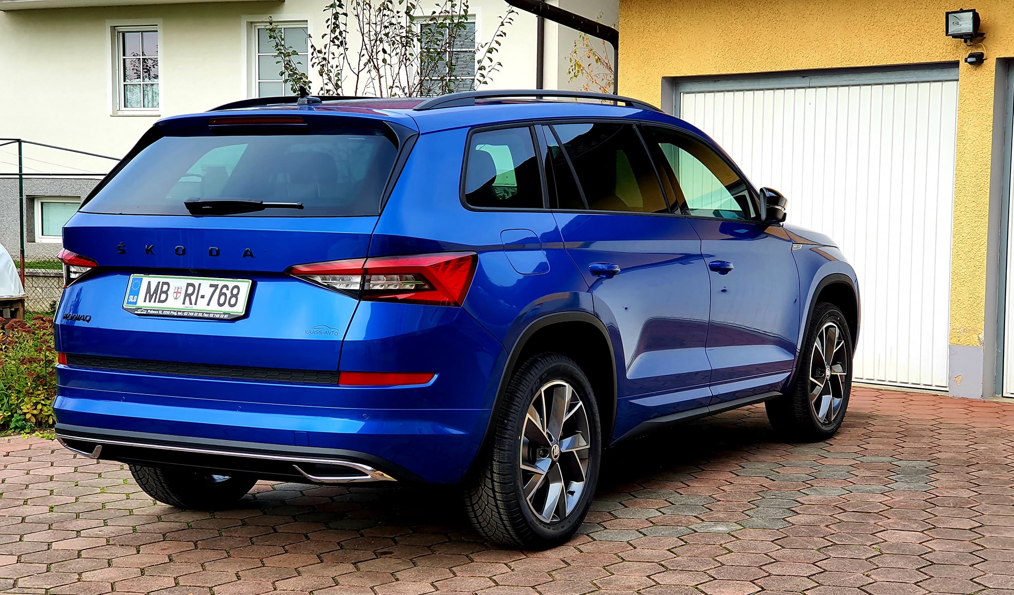
 1 pointJust spoke to Mike at Coverdale, and replacement loom ordered 👍 I did check that all the fuses were ok ( which they were) I even replaced the two 25 amp fuses as someone suggested trying new ones. No difference I’ll double check fuse 11 and report back......1 point1 pointmy Sportline is also home. Nonstandard equipement: Panorama, VC, Kessy, Amundsen+Navi..
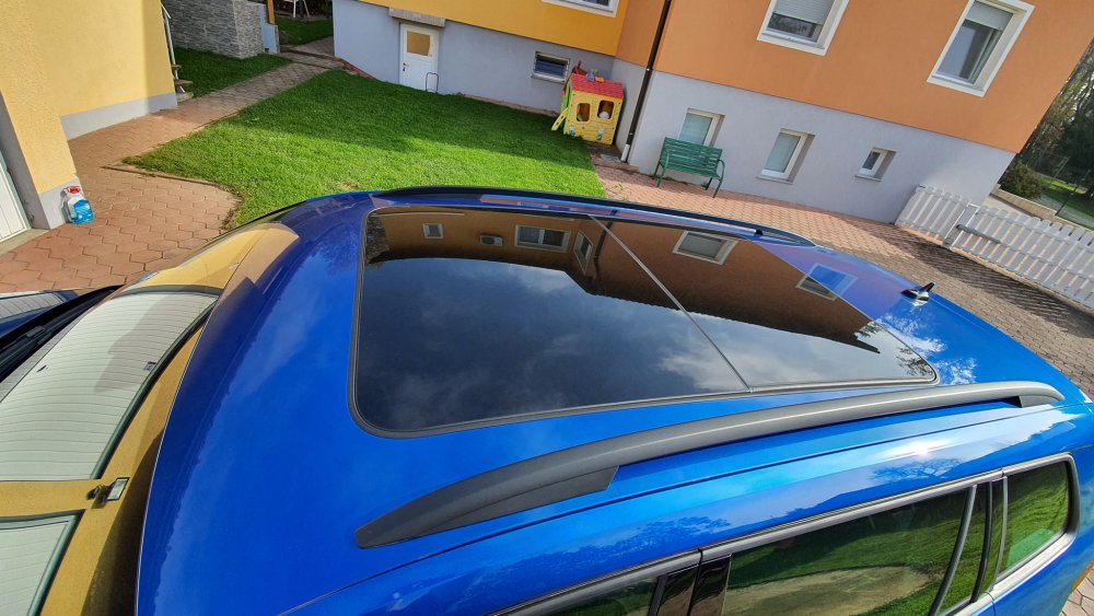
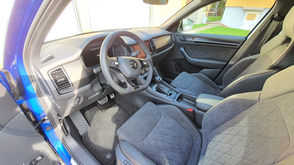
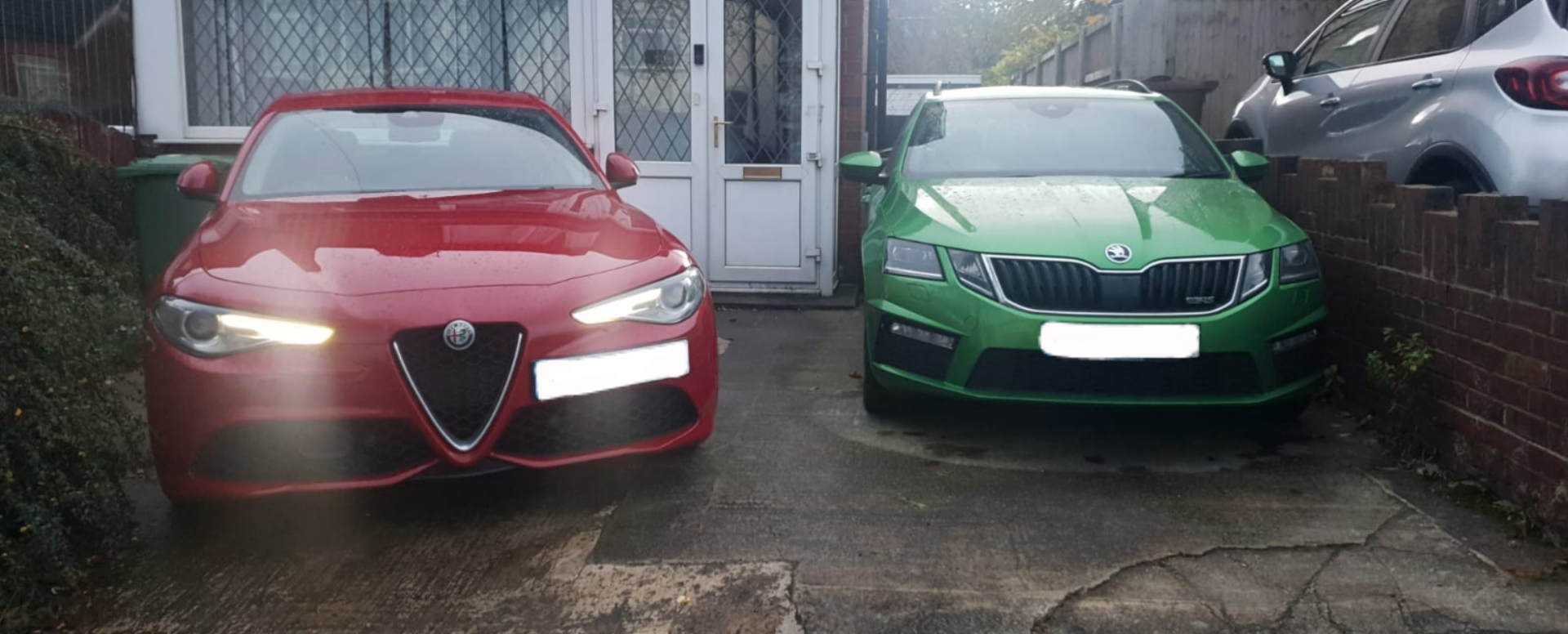
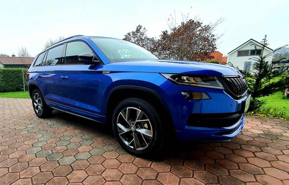


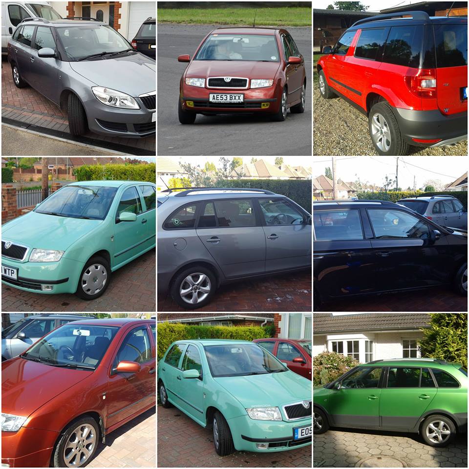
 1 point1 point1 point@Chaindrive pls let us know model number and SW version of unit you currently have - you can check it in menu SETUP then SYSTEM INFORMATION. Columbus is a solution for playing not only CDs but also DVDs and video files from pendrives and SD cards. It might be a bit expensive, especially if you want MIB2.5 as it requires 9.2" screen model number 5E091960D. However, if playing movies is not required, there is a cheaper solution to play CDs - I can rework SEAT unit to SKODA. They have CD drives. Contact me on PM if you are interested.1 point1 point1 point1 pointId say so yes, Id read somewhere a little while ago the fabia vRS tdi was destined to be a future classic. Trouble is they fall into the wrong hands, I paid good money for mine with 26k on the clock in October 2017 for £6k, mine had xenons, leather, cruise from factory painted black magic. People on Facebook were slating the price of it, but unfortunately the Facebook pages are full of lads who own the ropey examples and not prepared to spend the money. I too hope it goes to a good home! Dean1 point1 point1 pointLooks nice inside the cabin. That artificial engine/exhaust noise (presumably in sport mode) is awful. It sounds similar to the actual noise my old 4.2 V8 RS4 with Miltek exhaust used to make, but on the outside! His steering inputs were hard to watch as well.1 point1 point1 pointThe tyre sizes are different for 2 wheel drive and 4x4 versions when 19 inch rims fitted1 point1 pointHappens a lot! One bulb blows, and a resultant surge (for a split second) Pops the other bulb! Happens with my DRL's every now and then, has happened with my H7 headlights too!! (according to a mechanic friend f mine) I now drive round with a set of Lucas Spare bulbs under the floor in the boot (both the H7's and the DRL's)1 point1 pointIf you read Maggle's other posts, it appears they haven't got an VAQ/e-diff as there is nothing showing on the CAN-bus at that address. I can only imagine the menu item is changing the EDL via the ABS pump1 point1 point1 point1 pointI’ve returned the Carly dongle now. Easy process, all online through their EU website, postage paid on the return label produced. Thee was no way I was going to pay upfront for their annual subscription based on what I saw from the test diagnostic check.1 point1 pointI wouldn't go that far, I just compared the two light channels and pointed out the difference Glad to hear it worked though!1 point1 pointFollowing on from the photo by @pinkpanther's friend, this reminded me of one I took a few days ago.
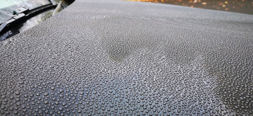
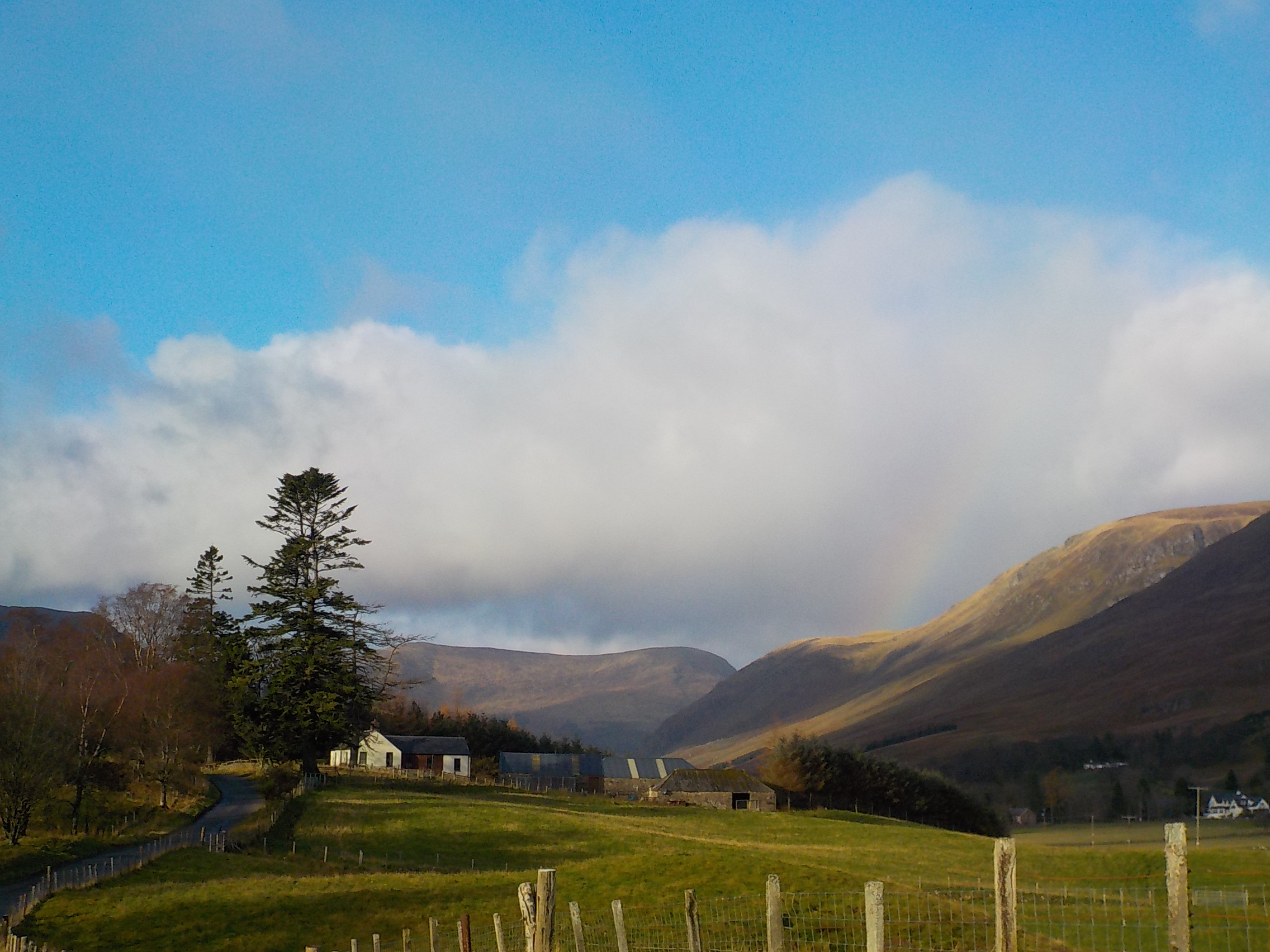
 1 point1 pointFriend of mine captured this sunset in Clevedon recently Bridlington this morning.......
 1 point
Important Information
Welcome to BRISKODA. Please note the following important links Terms of Use. We have a comprehensive Privacy Policy. We have placed cookies on your device to help make this website better. You can adjust your cookie settings, otherwise we'll assume you're okay to continue.


.thumb.jpg.f83a46b9b3c0d976b9dbffbb523c9874.jpg)


Account
Navigation
Configure browser push notifications
Chrome (Android)
- Tap the lock icon next to the address bar.
- Tap Permissions → Notifications.
- Adjust your preference.
Chrome (Desktop)
- Click the padlock icon in the address bar.
- Select Site settings.
- Find Notifications and adjust your preference.
Safari (iOS 16.4+)
- Ensure the site is installed via Add to Home Screen.
- Open Settings App → Notifications.
- Find your app name and adjust your preference.
Safari (macOS)
- Go to Safari → Preferences.
- Click the Websites tab.
- Select Notifications in the sidebar.
- Find this website and adjust your preference.
Edge (Android)
- Tap the lock icon next to the address bar.
- Tap Permissions.
- Find Notifications and adjust your preference.
Edge (Desktop)
- Click the padlock icon in the address bar.
- Click Permissions for this site.
- Find Notifications and adjust your preference.
Firefox (Android)
- Go to Settings → Site permissions.
- Tap Notifications.
- Find this site in the list and adjust your preference.
Firefox (Desktop)
- Open Firefox Settings.
- Search for Notifications.
- Find this site in the list and adjust your preference.