Everything posted by Breezy_Pete
-
Same applies with the grey/white wire, just comes from the 16-way connector at each motor. Look in the boots at the A-pillars for broken wires, both sides.
-
Can you just confirm which motor type you have, 6Y....part number, or 6Q...? The right angle connector mentioned above suggests the latter, I think, in which case my reference to 8-way connectors at the motors is wrong.
-
You may well find that it has lost comms with the master unit on the drivers side door. There's a 1-wire data link between the two motor modules (and nothing else) that is vulnerable to wire breakage at either A-pillar connector. It's a grey/white wire from pin 3 of each 8-way connector at the motors, via pin 5 at the 28-way A-pillar connections.
-
This may help with understanding the circuits: CFD explanations.pdf
-
No, not at all.
-
Numbers in rectangular boxes show the 'current track' number where that wire continues. 'Current track' numbers run along the bottom of each page of the wiring diagrams, not visible in that screenshot of @UrbanPanzer's. Generally they are to/from different pages, but are sometimes within the same page, to avoid having wires crossing others in the representation.
-
Yeah, that's what I was getting at. Just wondered if the clutch had been done, as it may as well have been while GB was off, unless fairly recent.
-
Take it back to whoever replaced the cylinder and allow them to finish the job that you have paid them for. Master or slave cylinder? New clutch too if the latter?
-
Will just be condensation caused during those recent short trips. Irrelevant.
-
Lots of short journeys?
-
Yes, two sizes for fronts in the parts catalogue, only one for the rears. I don't know what parameters Skoda/VW use to decide on sizing. Mass of vehicle, and top speed would be logical, but there may well be other factors. Lots of models have more variants than this. The first character in each of those PR codes is a numeral one, not a letter I, by the way. Even when build options stickers were put in Skodas, the front brake PR code was rarely, if ever, present among them.
-
Dunno, and dunno. Where did you order these items? Your discs should match genuine part number 2Q0 615 301H, to suit PR codes 1ZE, 1ZS. Pads are 2Q0 698 151Q.
-
Smartphone with front camera selected may be quite handy for looking up at stuff?
-
OBD, not USB, but owners manual might be worth a look. "Diagnostic socket" would probably be its description.
-
Yes, but watch out for rustiness in the heads, potentially causing non-full-depth bit insertion and head damage/rounding. Tx30 I think.
-
Yep.
-
Everyone has every part number. https://www.lllparts.co.uk/catalogs/skoda/CZ/FAB
-
Your rear brakes are described as C38HR Lucas, so I'd be confident in saying 38mm piston diameter. Seal kit has part number 8D0698671, which has been superseded by 2G0698671.
-
Check cabin fuse #14. Fuel pump relay is in position 4 (top row 4th from left) of relay holder, ECU relay in position 15 (bottom row, furthest right). The lack of ECU comms makes me think fuse 14, or ECU relay problems,
-
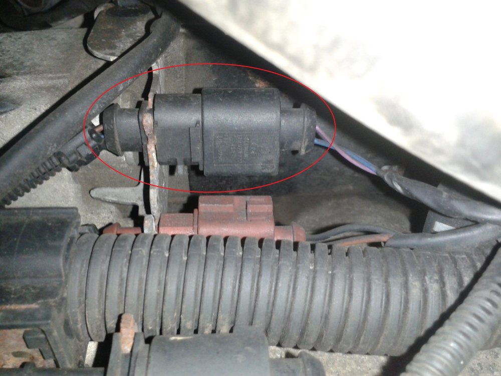
Find that plug/socket pair near the gearbox. Find damaged wire, repair it,
-
I will try to find which relay is associated with your engine ECU. The one near battery is for glow plugs.
-
I think the DF wire has since broken. Doesn't really seem to affect much (except on cars with ASR/ASR warning light). It's an "information wire" to the engine ECU, not a "control wire" from ECU. Most people don't believe this.
-
Ah! your last photo is alternator regulator/brushpack. Often replaced unnecessarily after these wiring breaks cause alternator faults.
-
Apart from the photo of the fault codes, I can't really understand what the others are showing. The interconnect at the gearbox bracket may look like this:
-
Alternator wires go via a black two-way plug/socket interconnect on a bracket in front of the gearbox. That's usually where they get damaged. Blue wire breakage causes battery light to not work, and problems with alternator boot-up. Other wire breaking causes DF fault, and ASR warning light after 10 mins running, on cars with ASR.