
Breezy_Pete
Sponsor
-
Joined
-
Last visited
Everything posted by Breezy_Pete
-
Yeti is probably very different, especially in 4WD version.
-
Fuse 21 (10A) feeds the brake light switch (NO) for the lamps, on a red/black wire, pin 1 of connector at switch. Feed to bulbs is the black/red on pin 4. This black/red from the downstream side of the NO switch also connects to inputs of ABS module and engine ECU. Fuse 32 (5A) feeds the brake pedal switch (NC), for the engine ECU's info on 'pedal-pressed', on a thinner blue/red wire at pin 2. Connection to engine ECU is via the black/green wire on pin 3. NO = Normally Open (no connection when foot off pedal) NC = Normally Closed (always connected except when pedal is pressed)
-
Within the vehicle voltage control unit above your clutch pedal, I think. It appears to have Climatic A/C, not Climatronic, judging by the dials and the word under the fan speed knob.
-
All (except suffix B for some reason) interchangeable according to the list of equivalent part numbers (in grey, below main item title) here: Front Bumper Reinforcement China 6Y0807109C (skoda-parts.com) Parts catalogue currently specifies suffix C for 2007 mk1. Not sure where D comes into it.
-
Fortunately, due to your post, confusion should be short-lived.
-
If I were you I'd grab a handle from a mk2 Octy at a scrapyard to try. Or buy a cheap secondhand 1J2... one online. The C81 at the end of the part number is just the colour code; functionally irrelevant.
-
Perhaps it is on mk3, but @hogun pen llyn asked about a 2012 car, which is maybe a mk2?
-
For RHD the part number starts 1J2 where LHD would be 1J1... Full current part number is 1J2 823 533C C81 at £21.10 + VAT from Skoda.
-
Good on you. That and the suffix-A part are interchangeable according to this page: Battery Cover Škoda 6R0915429A (skoda-parts.com)
-
Not at all, but it would be handy confirmation if there is a part number perhaps on the underside. 👍
-
Pretty sure Keith and Urban have given the correct info.
-
Pop the list up here, people will be much better able to offer advice with the additional information.
-
Yes, good sketch. I would also check for continuity from fan control module to that green plug/socket pair, and from the ECU to there also. (Not just short circuit to earth; fault codes can be misleading in their wording sometimes) Not sure which part of the loom goes to which, but if you leave green plugs mated, you can probably probe into the cable entry at that point. Pin numbers at ECU and FCM are in an earlier post, above.
-
Or maybe 1K0145838P?
-
May be able to read a part number off it? Possibly 1T0145790B?
-
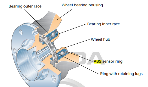
I doubt you'll find any such thing, unfortunately. The ABS sensor 'looks' at magnetic patches on the inner face of the wheel bearing, not at anything on the driveshaft.
-
Yes, I think that's most likely of all the possibilities. Or perhaps just the needle put back in the wrong position after dis-assembly of the cluster?? It could also be bad information from the crank sensor, but I think that would cause other starting or running problems. VCDS or VCDS Lite could be used to tell you what rpm the engine ECU is actually outputting to the cluster.
-
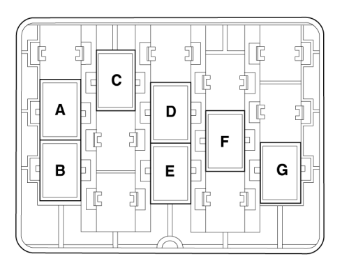
Green connector apparently lives in position A of this image: I think that matches with an empty position in the above from the Golf video. Different engine in the Golf maybe?
-
So you think the engine really is running that slowly? Cos that's the only way the pedal can be involved.
-
No warning lights or fault codes? Rev counter is normally displaying what the engine ECU calculates from the information coming from the crank sensor. You could read what the ECU is seeing with VCDS or similar and compare that to the needle position. Could be one of 3 things: Engine really turning very slowly (unlikely I think). Crank sensor giving bad output at those times (see what VCDS reads). Dial displaying the info incorrectly.
-
Oh, OK, sounds like the wire rope or clips of the mechanicals of the window are that problem. Listen for a click from the relay within the passenger motor module if you try to raise or lower it. That would confirm that the electrics are trying to move the glass, but can't.
-
Have you checked the fuse for pass window? (And checked that it is in correct position?)
-
Oh, then check fuse 50.
-
Try fuse 50. Wait, no, I think it would only be that if the car doesn't have start/stop. I assume yours does?
-
Suffix AJ does seem to be compatible judging by both appearing on this page: https://www.skoda-parts.com/spare-part/1k2721503aj-accelerator-pedal-skoda-45060.html But the real problem might be a damaged wire or bad contact, not necessarily the pedal electrical part itself.