Breezy_Pete
Sponsor
-
Joined
-
Last visited
Everything posted by Breezy_Pete
-
Why all the missing fixings? The wire you've taken off, and all the missing nuts on the plate behind the fuses will need to be there for things to work right.
-
I think the little green plastic bits may hinge open to give you a view of the metal strips?
-
Can you stick a photo up? Got a multimeter?
-
Have you checked the strip fuses on top of the battery?
-
True for traditional alts, not so simple with newer set-ups where the alternator is controlled by external electronics.
-
Measure 'turns ratio' (crank pulley diameter/alt pulley diameter) then pick an engine rpm after a quick browse here: Experimental study on the effect of alternator speed to the car charging system (matec-conferences.org) The situation is made less predictable by the fact that you will presumably have start/stop and a battery management module that will 'tinker' with the alternator output voltage according to its whim, which isn't likely to prioritise battery lifetime.
-
You could research what an appropriate voltage value of the diode might be for this application and probably get them for about 50p for the pair from the likes of RS/Farnell. The motors are (nominal) 12V driven, I expect (based on earlier cars with separate central convenience module). A transil/transorb to suit an approx 14.5V supply would seem to be the badger.
-
Could do with someone who can read Russian to see if the photographed text refers to that red symbol, other than that it looks to be mainly a case of finding the correct three wires to string the diodes between. The pin numbers they come from at the lock module are 1, brown wire; 2, blue/yellow wire; 3, violet/yellow. Note that there's also a yellow/blue wire to potentially confuse matters, and another brown wire from pin 6. Typing that has made me realise that the red symbol is probably there to warn "not this brown wire, it's the one from pin 1 you need to connect the diodes to". The three correct wires are slightly thicker than the others, which should help to spot them.
-
Will you give it a go yourself? I expect a Skoda dealer will sell you the two diodes. Not sure what the red symbol on the earth connections is all about.
-
Here you go, probably enough to work with: MLab.org.ua • View topic - VW Jetta 5 - not clear glitch with central locking (mlab-org-ua.translate.goog) Seems to be suppressing spikes from the lock motors.
-
The repair kit appears to be a protection diode ( https://en.m.wikipedia.org/wiki/Transient-voltage-suppression_diode with flying leads coming off it https://izap24.kz/tovar/14806306_fragment-svyazki-5j0971658-skoda-novaya-original.html You can probably view the TPI via erWin Skoda, but you'd have to pay a small fee for access. There may be someone on here who knows what it says though. I suppose it just tells you where you graft in that/those.
-
Screwdriver like you did upthread?
-
I thought there was a step where you did have to do that but it's all hazy memories from when I did the OEM radio remote upgrade on my spare Polo.
-
Does the programming you've been trying involve turning a key in the door lock?
-
Just move the wire across and try it. It'll be fine.
-
Does the broken one say 50 anywhere? Check with both halves removed, both side.
-
That's your problem, move the unused one that's next to it (no wire) into its place, checking that it says 50 on it somewhere, it looks the same width at its narrowest point so probably same value. Edit, or just undo the one nut and move the wire across onto number 6 if it'll reach, that should be easier.
-
Yep, in my experience sensor 1 is always closer to the engine's exhaust manifold than sensor 2.
-
Not a bad idea at all.
-
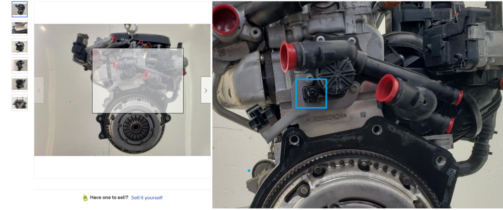
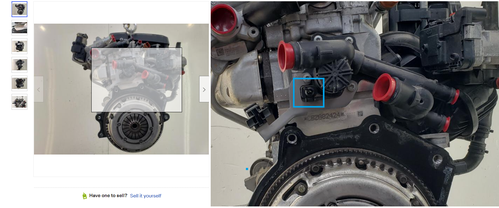
Doesn't look like a walk in the park, I must admit. First thing to do is try to get some phonecam photos maybe, just to see if there's anything obvious like a busted wire near the connector cable entry? To get the sensor out, it looks like the lower two screws holding the coolant flange and steel bracket to the head need to come out, then move the bracket aside. That'll give you access to the single screw holding the sensor in (obscured from view behind the bracket in above pics).
-
Ah no, that's the version for the non-tsi engines. The one you need looks like this: 03f919501a: Search Result | eBay
-
Is that steel bracket obscuring the view and confusing you about what you've got? What does the one you've been sold look like?
-
Looks like you need 03F919501A if yours is a CBZB engine like the one in the photo.
-
No, the ebay listing is for the whole engine, seems like a drastic solution to your problem! 😁 I'll find the part number for you in a sec.
-
I expect this is it here (it's almost always easier to look round an engine via ebay listings' photos):