Breezy_Pete
Sponsor
-
Joined
-
Last visited
Everything posted by Breezy_Pete
-
I can't recommend bypassing designed thermal/ overcurrent cutouts, but I must admit I did solder the thinnest bit of wire I had handy across the break and returned it to Keith to try, out of curiosity to see if the faults were resolved. The fuel gauge and ambient temperature readout were now operational, but there was a problem with the immobiliser which prevented full success. I suspect that maybe coding in a replacement cluster may have caused this original one to be seen as 'foreign', but my knowledge of such things is inadequate to be sure.
-
Yes, that's quite possible/likely. The way the heaters work is that they get a constant 12V feed on one side of them, then the ECU modulates the return/ground path on/off in Pulse Width Modulated fashion to provide easily (digitally) controlled currents through each heater.
-
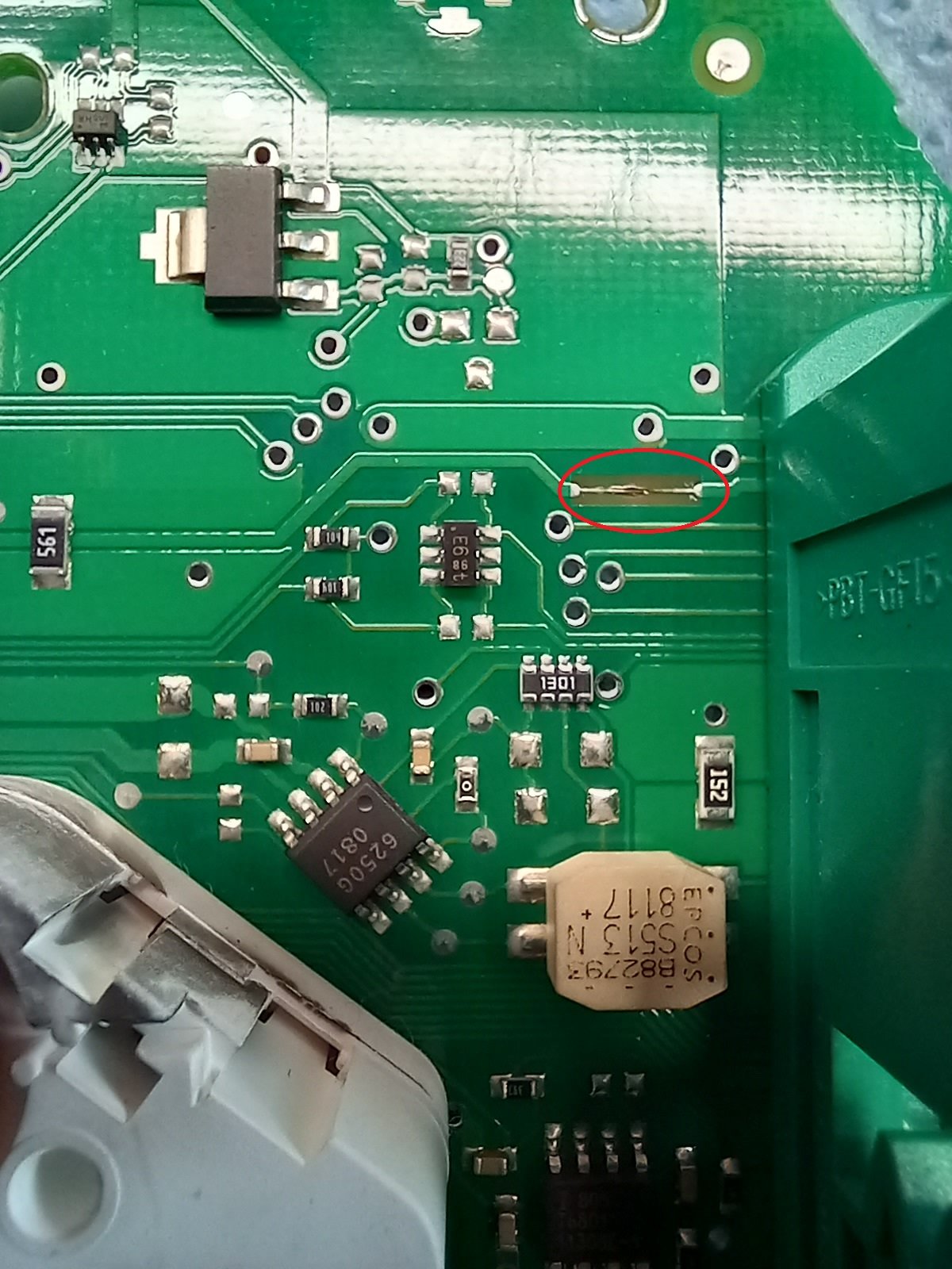
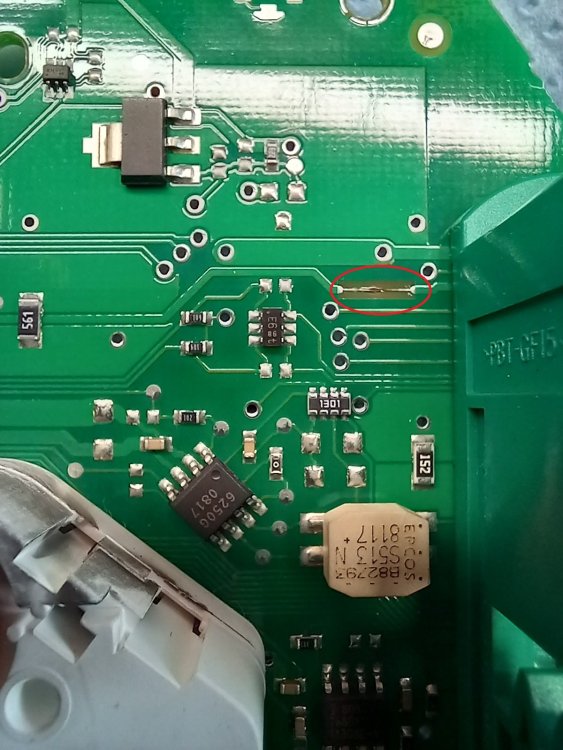
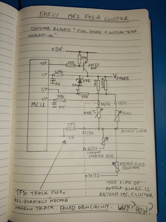
I didn't spot anything visually the first time I looked at this cluster circuit board, but the second time I picked it up my eye was drawn to something near the green connector plug: This strangely necked-down uncoated bit of track. Under the microscope it was clearly ruptured, and measured open-circuit, infinite resistance with a multimeter. Checking which pin it was going to from the right-hand end, it was pin 32. Wiring diagrams call this connection 'sender earth' and it goes to a few senders including fuel gauge, outside air temperature, coolant lack sensor, screenwash fluid level sensor etc. It seemed clear that none of these things, where fitted, could operate as designed with this ruptured track. I conferred with Keith as to whether there'd been any known external fault, like a wiring short or similar, preceding the failure, but he was not aware of any such thing. The replacement cluster did not suffer a similar fate, so it seemed most likely to me at the time that there must be some other fault, on the cluster circuit-board that had caused this track to fail. So I set about reverse engineering the circuit. Not too much to it thankfully, and this is what I came up with: MCU on the left is some big chip, presumably a microcontroller. An output (I assume) is used to turn on a pnp transistor (not necessarily all the time) which supplies a voltage to both fuel gauge and outside temperature sensors (V share) limited by a 5.6 volt zener diode, via a couple of resistors such that the gauge senders are the bottom half of two potential dividers. The voltage V share and these two mid-points of the two potential dividers are monitored by three input pins of the MCU, I suspect analogue inputs. I didn't map out the onboard circuitry for coolant lack or washer fluid lack sensors. The necked track going to/from pin 32 just goes to the board's 0V. I could not see any obvious single-component failure in this arrangement (on the board) that could cause a large current to flow back into pin 32, so I'm not really any the wiser as to why the track failed at this 'necked' point, nor why it is narrowed down like that. A hunch I have is that it is to provide a guarantee that only a pretty small current can flow through the fuel gauge sender, which is after all in a hazardous environment? Didn't spot a similar feature on the Mk1 cluster I have in bits though. If anyone can explain it, I'd love to hear from you. When I google 'track fuse' there's a fair bit of discussion about them, but mostly fairly disparaging, along the lines of 'why wouldn't you just use an actual fuse?'. I suppose it could have corroded a little, because of the lack of solder-resist coating, making it more susceptible to runaway ohmic heating than when new? Or had a slightly dodgy bit of etching so it was even narrower than intended at some point? It appears to have folded back on itself to the left when I zoom in?
-
If you want to continuity-check wiring I can probably find the pin numbering details for you as reqd. Well worth looking thoroughly for external, visually-apparent wiring damage first though, as said.
-
You don't say whether or not you've double-checked the fuse I mentioned. Did you?
-
@rum4mo is your man to provide links to the several other threads detailing this alarming failure. Not restricted to Skoda brand, any others sharing this engine, I guess.
-
Thanks for introducing this Keith, and thanks for sending the cluster so I could take a look. This failure was mentioned by Keith in another recent instrument cluster related thread, and my interest was engaged because I remembered once looking at the circuit dealing with outside temperature and fuel level within a Mk1 Fabia cluster, finding them to share some components. I thought that it might be possible to repair this cluster's failed functions if I could find such a component in a failed state. I did find a failure, which has restored those functions following repair, but it wasn't a component as such. During the process I have sketched out the circuitry associated with the two functions, by close inspection of circuit board. The root cause of the failure remains a mystery, unfortunately, as does the purpose of the 'thing' that failed. Mk1 Fabia cluster doesn't seem to have the same 'feature'. Pics coming this evening... 😊
-
May as well do the resistor first, to restore ventilation options. Then drivers side wiring bellows; then - if faults remain after fixing any problems there, the wiring bellows on passenger side.
-
And the other side.
-
Find the cabin air entry point in the 'water box' which I would imagine in a RHD car is the right (as we look at diagram) rectangular hole in item 3 here cross panel; wheel housing; a-pillar - Superb(SUP) [EUROPA 2012 year] (7zap.com) That leads through to cabin fan etc inside car. Above passenger footwell area. Now look at the equivalent area on the other side, which would be the entry point on a LHD car. This would seem like a candidate for water entry to above pedals on RHD car if not sealed properly.
-
Top guess.
-
It takes two to communicate, why decide that the BCM is the problem, rather than the ABS module? Who are 'they'?
-
Not tempted to mend it with external resistor?
-
Surprisingly, the compressor still operates at a low duty cycle even when A/C is turned off.
-
Check connection to starter motor solenoid isn't broken.
-
Your A/C compressor is driven by the engine, so can do nothing to produce any cooling at all when the engine is not running.
-
What are the other problems?
-
You'll probably get better advice if you describe what your 'warm running problem' is. Any fault lights and/or fault codes?
-
-
-
-
-
Find it yet?
-
Sounds mechanical to me, not electrical/electronic.
-
Can you clarify what you mean by this, please? A little bit of working OK or a little bit of not working OK?