



Breezy_Pete
Sponsor
-
Joined
-
Last visited
Everything posted by Breezy_Pete
-
Never mind wyx, I'll pop you on my ignore list and trouble you no further. G'night and goodbye.
-
I see the point of car forums as helping others to fix their cars. I see using them to try to promote political or ideological stances as misuse, basically.
-
As I said, I don't need you to agree.
-
Just seemed (to me) hypocritical (of you) to bang on about 'FUD' stuff whilst trying constantly to influence people towards EVs and away from conventional cars. I don't need you or root to agree. 😁
-
Not helpful.
-
No, hence the 60/70 bhp question. Mk1s were 54 and 64bhp. Not sure if the single cam ones continued into face-lift mk2s though.
-
So it's OK to try to make everyone feel guilty who may have recently purchased or be planning to purchase a conventionally powered car, if it's a tit for tat attack on another poster?
-
Can you post a picture of the engine? Both the variants I referred to are 1198cc. Are the spark plugs vertical in the middle of the top of the engine, or sticking out the front at a steep angle? Reason for it being important is that one type tends to suffer much more damage than the other if the chain slips.
-
Is this a single cam 60bhp engine or dual cam 70bhp?
-
Possible chain slip. Check alignment of cams under the covers at the gearbox end.
-
What, like this?
-
That's not ideal.
-
Open circuit problem sounds like a blown fuse.
-
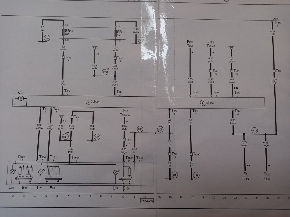
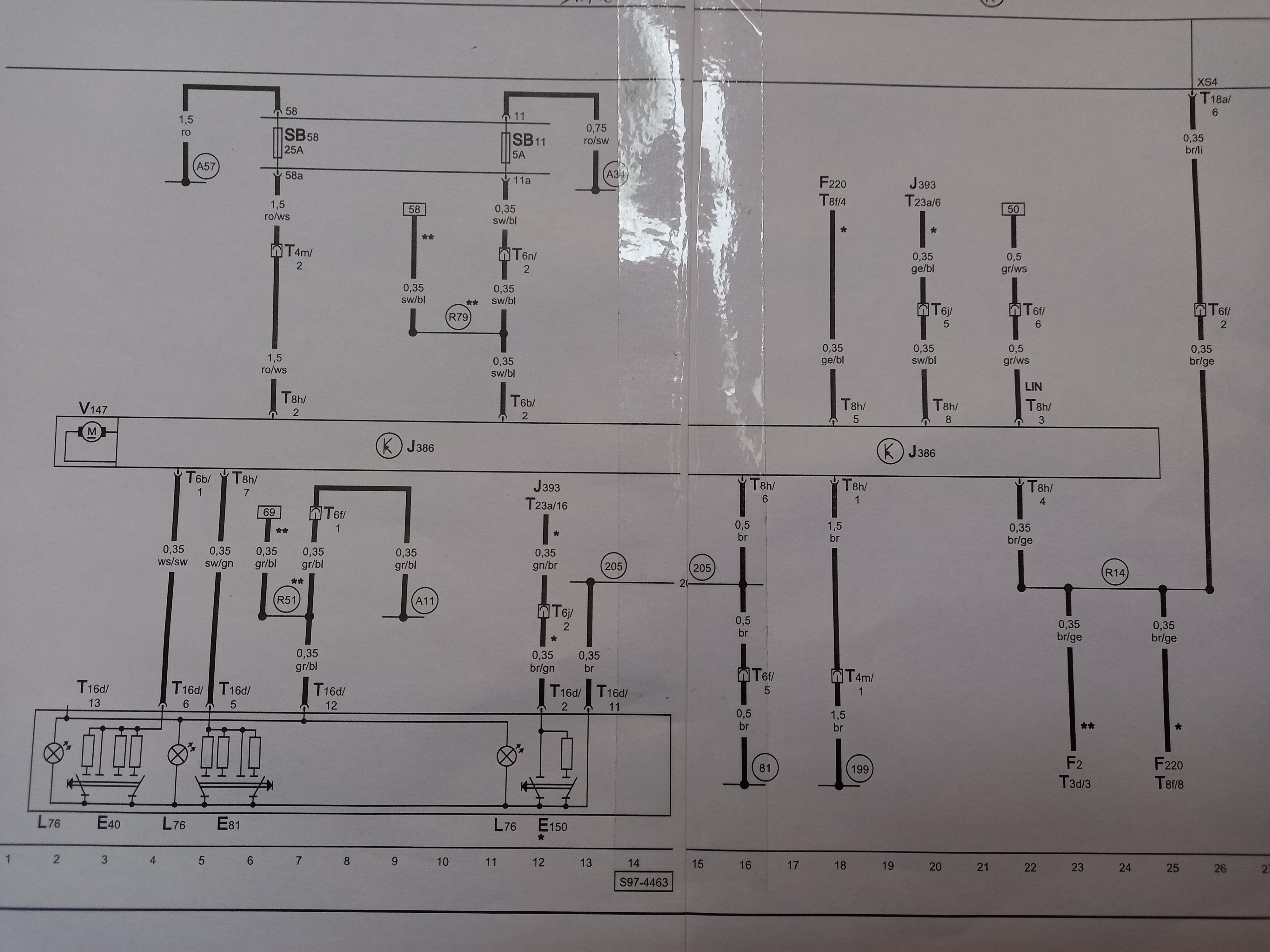
No, I asked if mixing was how you were proposing to get 40-50% ethanol fuel.No I haven't tried it, and I have no idea how far you could go. Do the experiment yourself.There are two main types of oxygen/lambda sensor, one with just four wires which is what yours has both pre- and post cat, then there are wideband ones with five or six wires that are a bit more controllable, giving engine management more flexibilty. Earlier versions of the 1.2 12-valve had these more expensive 'better' sensors, but since about 2006 just the cheaper four-wire ones.Yep, no wideband on a 2009 BZG. I guess you are proposing to mix partial refills of E85 and E10 or E5 to get your suggested 40-50% ethanol. But why not just try it with increasing levels of fill/mix with E85 and E10 or whatever the standard petrol is there? If it starts running badly you'll know you've pushed too far in the direction of ethanol. Carry a spare 5 litre can of 'good' petrol so you can adjust the mix at the roadside.I finally got around to checking this just now. with 13.8V main supply to the module, I see almost exactly 13V at the two switch input pins (left window switch on pin 1 of 6-way, right window sw on pin 7 of the 8-way). When I lift either switch partially up the voltage at the corresponding pin goes to 6.8V approx, when pulled fully up as far as it goes, 3.3V. When pressing down on each switch I see 1.3V at the corresponding pin, when fully down it is 0V. These voltages will scale with the supply voltage, so will all be higher with engine running than just with ignition on, except for the 0V one.People will post whatever they wish to. Has battery charging come up yet, I don't read everyone's posts? 😁I think they are blind holes, and that's why the threads don't get corroded (no water access in from far end). Aftermarket versions, but a couple of examples in ebay listings: NEW SEAT IBIZA MK3/MK4 FRONT LEFT STEERING KNUCKLE WHEEL BEARING HUB (W/CARRIER) 5060952960659 | eBay (256mm type) NEW SEAT IBIZA MK3/MK4 FRONT PASSENGER SIDE HUB STEERING KNUCKLE (288MM DISC) 5060952963810 | eBay Bit harder to see on this one, but a genuine one i'd've thought judging by condition: 2010 SKODA FABIA 1.2L Petrol PASSENGER FRONT HUB 6Q0407255S | eBayTop right of your post there are three dots, click on that within half an hour of posting and you'll see an edit option. The half hour is a guess, it may be more/less time. It's infinite if you have Freedom membership.Pay the small sum required to stick it in the classified section.The wiring diagram for driver's side looks like this. J386 is the motor module. Below it in the diagram is the switch panel. F220 is the lock module. J393 is the central convenience control unit. The fault on a mk1 Fabia is almost always inside J386.






Important Information
Welcome to BRISKODA. Please note the following important links Terms of Use. We have a comprehensive Privacy Policy. We have placed cookies on your device to help make this website better. You can adjust your cookie settings, otherwise we'll assume you're okay to continue.