Breezy_Pete
Sponsor
-
Joined
-
Last visited
Everything posted by Breezy_Pete
-
I believe your car has the hall-effect type of brake light switch, mounted on the brake master cylinder, rather than the pedal. The garage(s) are possibly unaware of this, so looking in the wrong place. See if there's any sign of wiring damage near to it (access is horrible on RHD cars though, I expect).
-
I'm not sure there's much to be gained by any further interaction with them, to be honest.
-
Same bolt, fibbing garage.
-
Some do, some got 256mm; it's a strange one.
-
027 will be fine.
-
You know coolant is roughly 50% water, right?
-
I bet the bolt didn't come in the kit they bought, (it wasn't in the genuine VW kit I bought for the 9n Polo) and they interpreted that to mean it was OK for it to be re-used. Hard to say for certain that it'll be fine; if it was going to break it would probably have done so during tightening. Bigger risk is that it wasn't done up tight enough, and might subsequently loosen, but it doesn't sound like you'll get an honest answer, if any, to what spec and tooling was used to tighten it. If it's something that's going to cause you ongoing anxiety, I'd suggest getting another garage to quote for replacing it.
-
Not as extreme as one I did recently. 150Nm plus 180°, on a 9n Polo, took a hell of a lot of doing. Is it a garage you hope to use again, and have history with? They won't enjoy being told the job hasn't been done right, obviously, but if they know you, and are a bit grown up, they ought to at least discuss it.
-
What torque plus angle does the manual specify, something quite extreme I'd expect? Brave to reuse it, if done up again to full spec.
-
Open circuit (broken or very badly connected wire) is consistent with a falsely low temperature reading, not a short circuit. Most likely breakage point would be just outside the cable entry of the connector, so ought to be obvious. What occasionally happens instead is that the metal encasement of the sensor goes porous, and coolant gets into the innards of the sensor. You'd think that replacement would solve this, but unfortunately once it's inside the connector, it can corrode the connections of both sensor and loom connector contacts, and even wick its way along the wires, within the insulation jacket. If you unplug the loom connector of G62, does it seem damp inside, and do the connector contacts look clean and shiny, or crusty and corroded? Good light and magnification may be required to see.
-
Yes, except for 288 to 312mm change. Yes, for the third time now. Have a look at your brakes, confirm that you see FSIII on the outside of the caliper casting. Look at how the caliper mounts, where the disc sits and imagine trying to squeeze a bigger disc into the same diameter opening.
-
If it currently has 256mm discs, it has the FSIII calipers. On Fabias these calipers fit onto the integrated carriers, no bigger discs can be or are used on FSIII calipers on Fabias, The three variants on Fabia mk1 are: FSII caliper with 239 discs, and bearing housing with integrated carriers to suit this disc size. FSIII caliper with 256mm and discs and different bearing housings with integrated carriers to suit this disc size. Lucas calipers with 288mm discs, carriers that bolt onto the again different bearing housing.
-
With the integrated carriers on your bearing housings, you can't fit anything bigger without changing the whole bearing housing. You'd have to fit the suffix S parts of item 7 here: https://www.lllparts.co.uk/catalogs/skoda/CZ/FAB/453/4/407/407010 Waste of time and effort.
-
Yes, don't even start buying stuff until diagnosis is complete. It's a big job that you really wouldn't want to do unnecessarily. I won't do another, nasty engine to do such major work on. Easier to fit another engine.
-
Or perhaps more likely, part of it jammed up the crank pulley, causing it to stop rotating abruptly? Not sure.
-
There is, the timing belt is fully covered, albeit by plastic covers. I guess the aux belt remnants flailing about managed to destroy part of the covering.
-
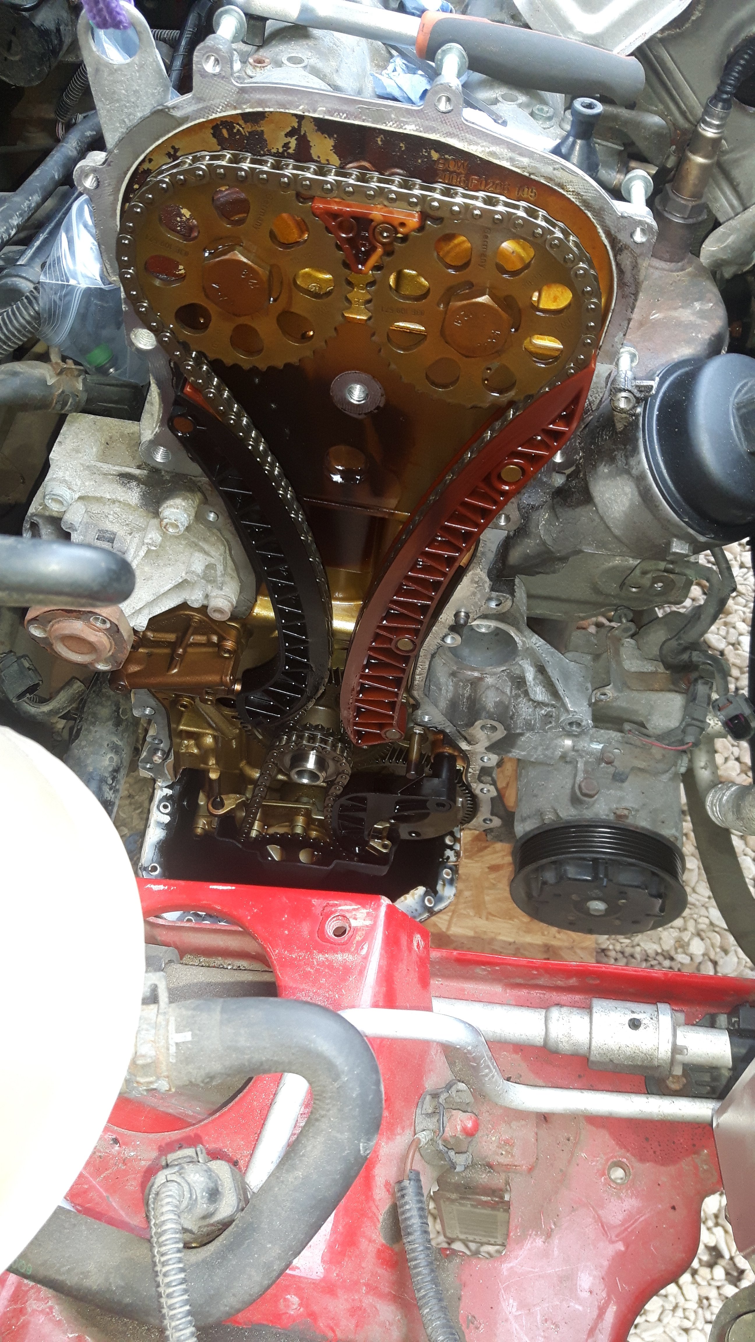
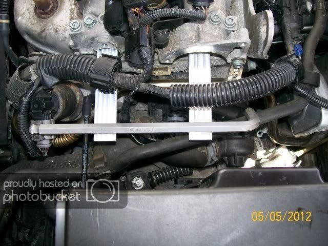
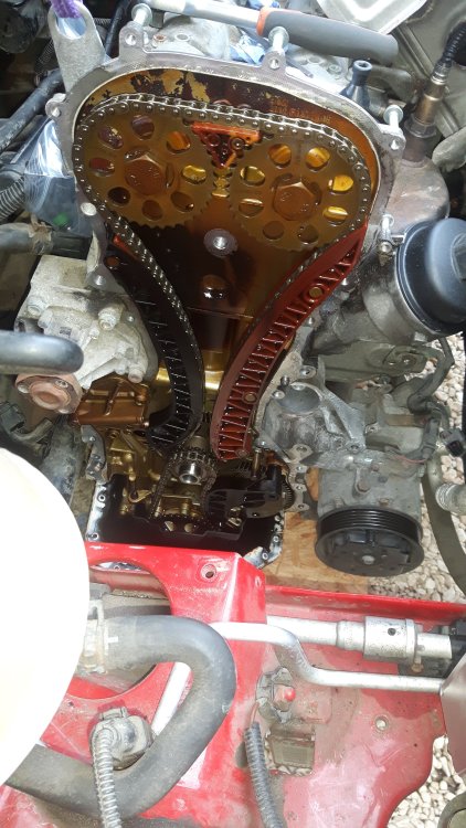
Remove the two covers from the gearbox end of the cam cover which give you access to where the cam locking tools fit. You will be able to see the slots in each cam that the tools fit into. They should be always parallel to one another; and when cylinder 1 is at top dead centre, they should be parallel to the head gasket. If either of those conditions is untrue, the chain has jumped. Here's a pic of ours when newly acquired, with some flat bits of alloy stuck into the slots to investigate parallelism (at TDC). Changing tensioner alone is not possible without almost all the same work that would be involved in changing the whole timing kit, it lives under the one-piece alloy cover at that end of the engine. There are horizontal locating dowels in the engine block that mean the cover has to be removed horizontally after all the fasteners are removed. It will probably break if attempts are made to remove it in other directions. Tensioner visible here with timing cover removed (in 2020), just below water pump. And locating dowels can be seen in the block too. Since the cover is attached by sealant as well as about 30 fasteners, to camcover, head, block and sump, it is difficult to remove even with the sump off, let alone without, where the sealant to sump would have to be broken in shear. Would be nigh-on impossible to refit the cover to the sump (with sump left on) oil-tight using sealant unless the dowels were removed and omitted. The image shows the sump loosely refitted after the timing cover was removed.
-
The VW group part number may well be visible on the rear face of the alternator. Match that exactly and you will be fine.
-
-
-
Having said all that, a bad connection would tend to make the light(s) not work, rather than stay on when they shouldn't be on, unless the two wires are shorting together somewhere near that same area. Cutting that short section of trunking off may reveal something. Could also be that the switch contacts are sticking, but probably best to improve the wiring situation first, if any damage is found.
-
Yes, it's quite common for the wires near that connector to degrade, possibly due to the transitions between relatively stiff plastic convoluted trunking and the free bits of wire just before the connector entry. Vibration and engine movement can cause the insulation to crack thereabouts, then water can get in and turn the copper conductors within into green and black dust over time. It's probably best to remove that section of convoluted sleeving completely, buy a connector with tails of wire prefitted, and keep cutting back the insulation of the existing loom until clean bright copper is found. Then splice the wires together from new connector and loom. Part number is just visible in your photo, 1J0973702, I think.
-
For that VIN we get halogen headlights as follows: 6Y2941015R for the left side of the car, 6Y2941016R for the right side. Both still available from Skoda at £135.50 plus VAT each, if you're feeling wealthy.
-
Just about to go out briefly, but if you ping the 17 character VIN across I can look up later for you.
-
The blue square is your oil pressure switch. When these start to fail, oil leaks out through them.