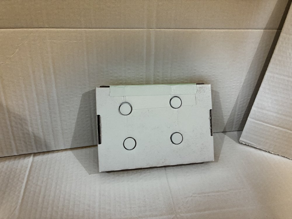
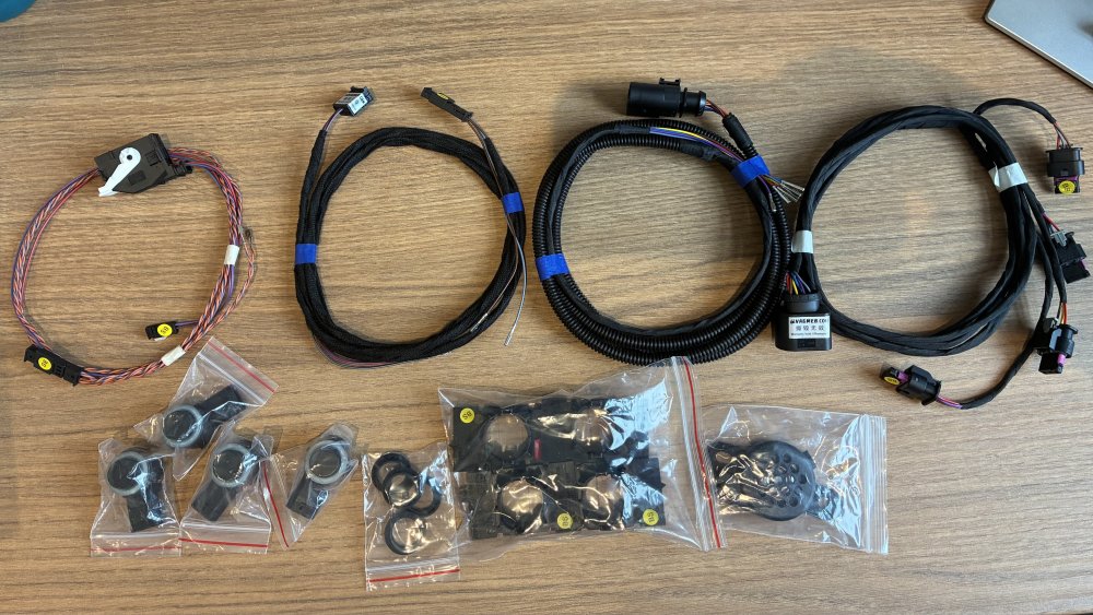
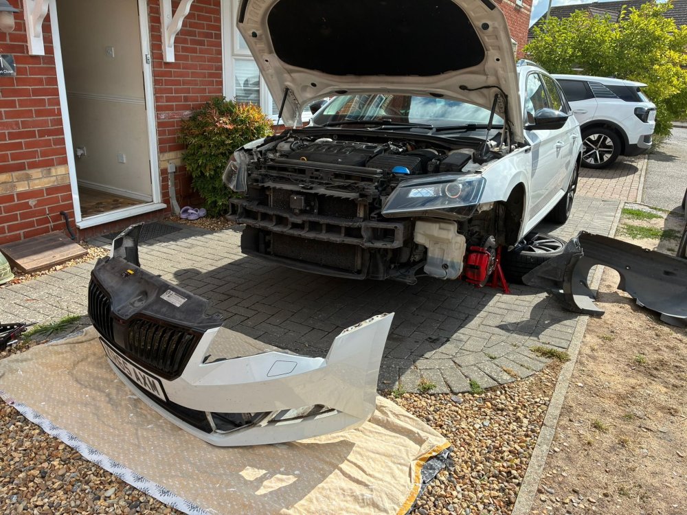
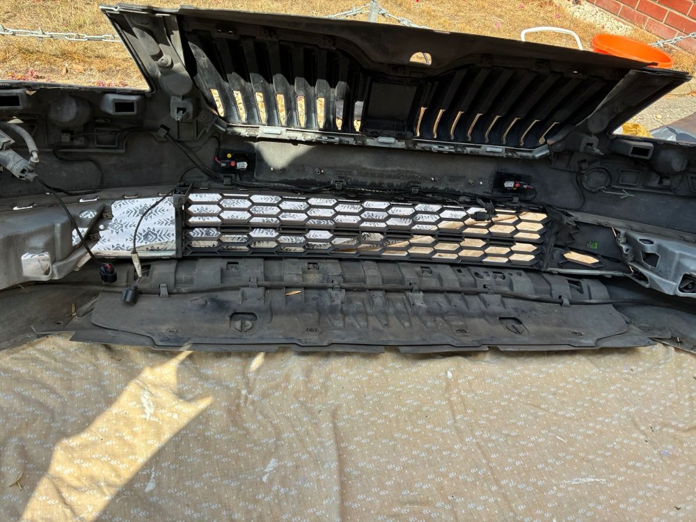
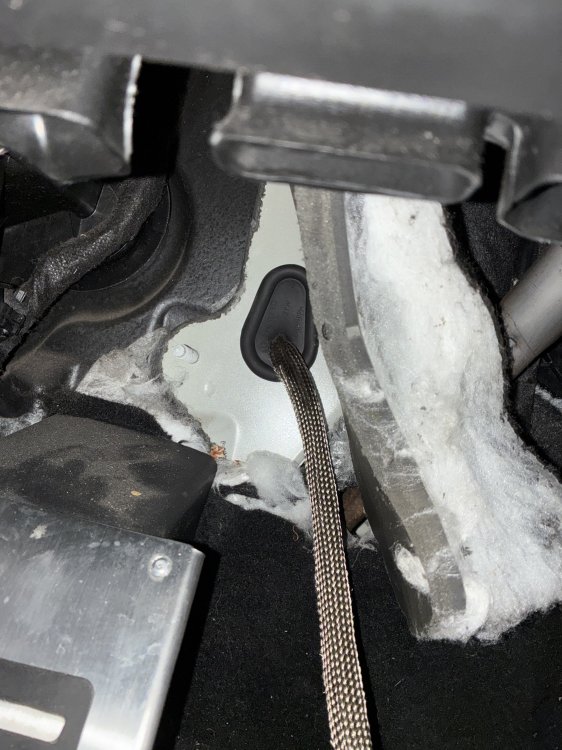
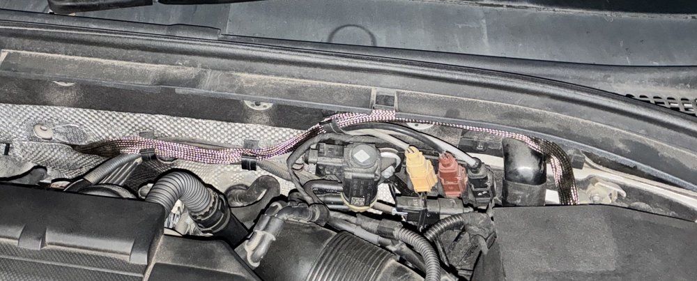
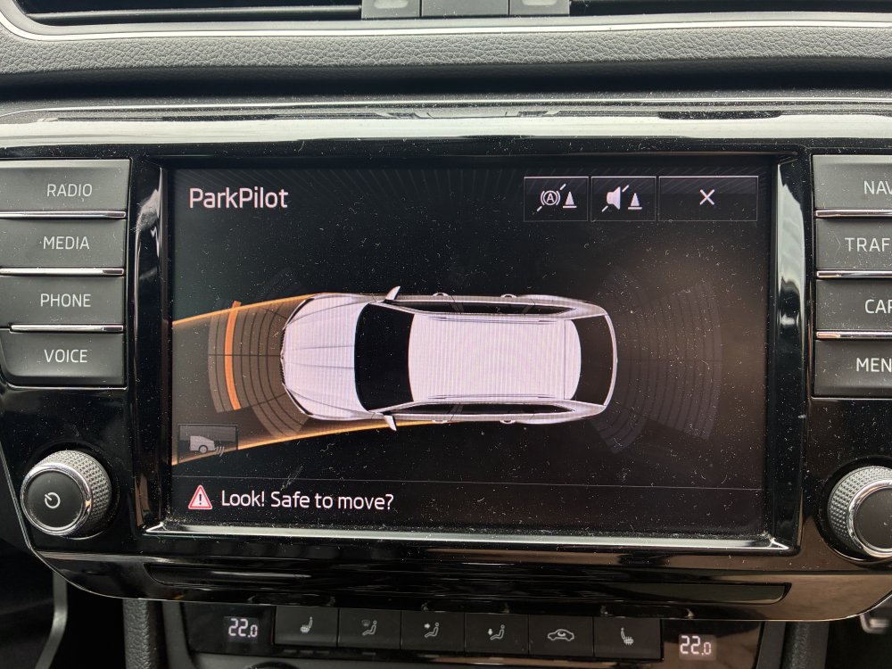
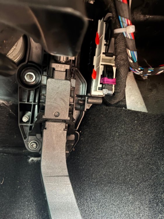
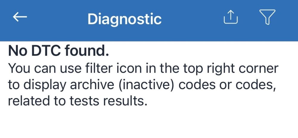
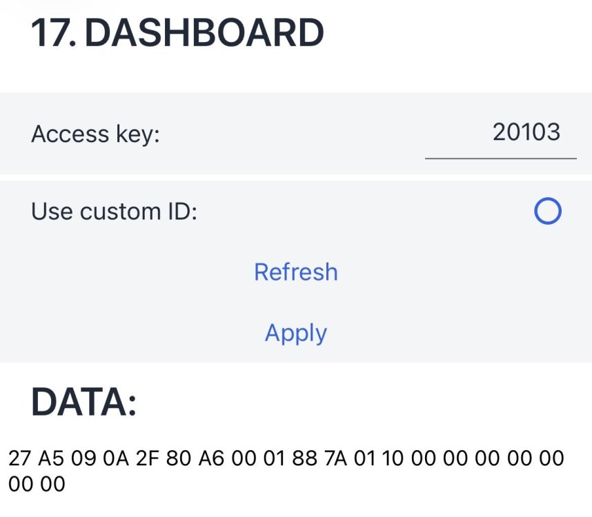
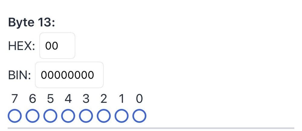
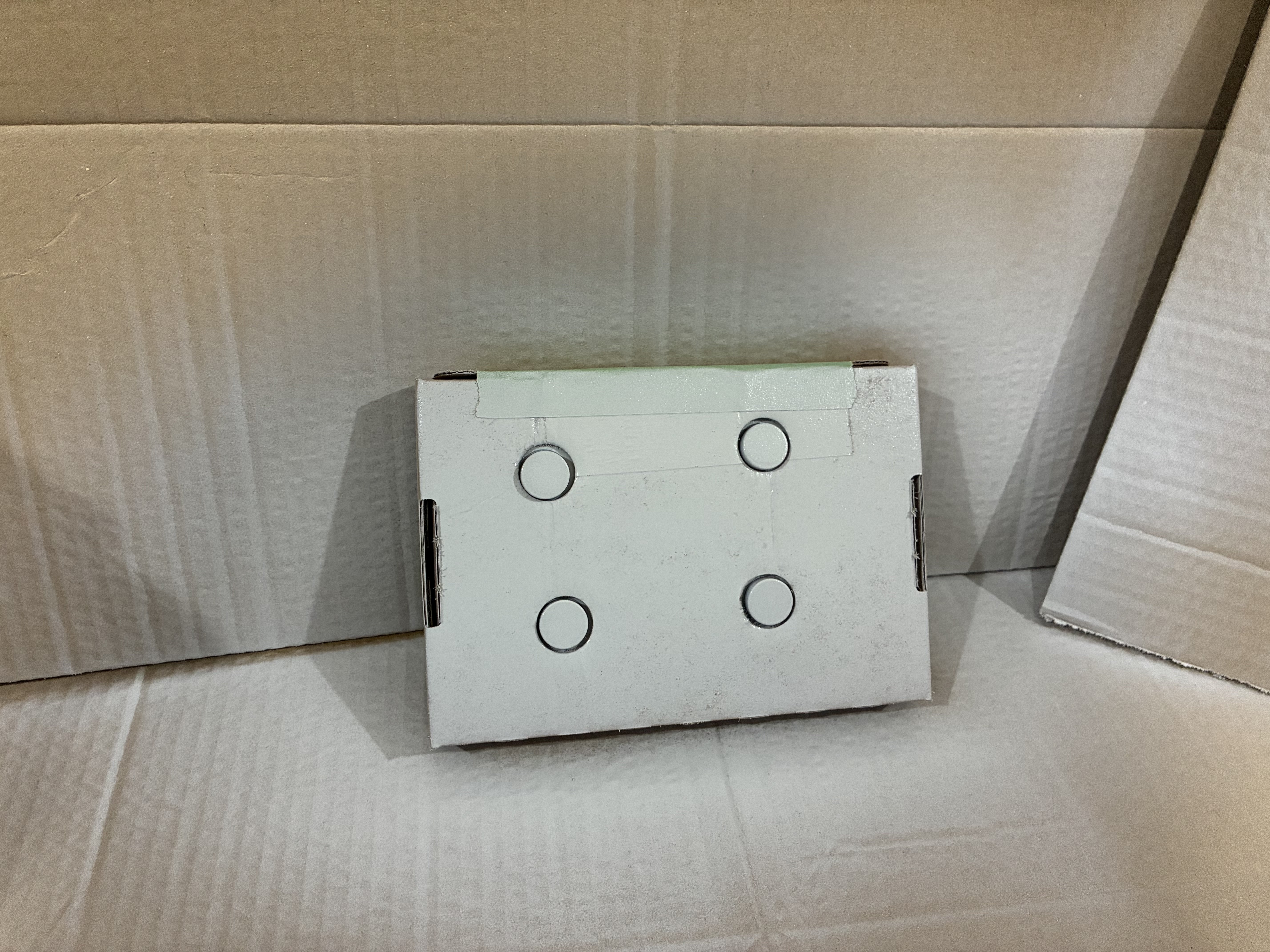
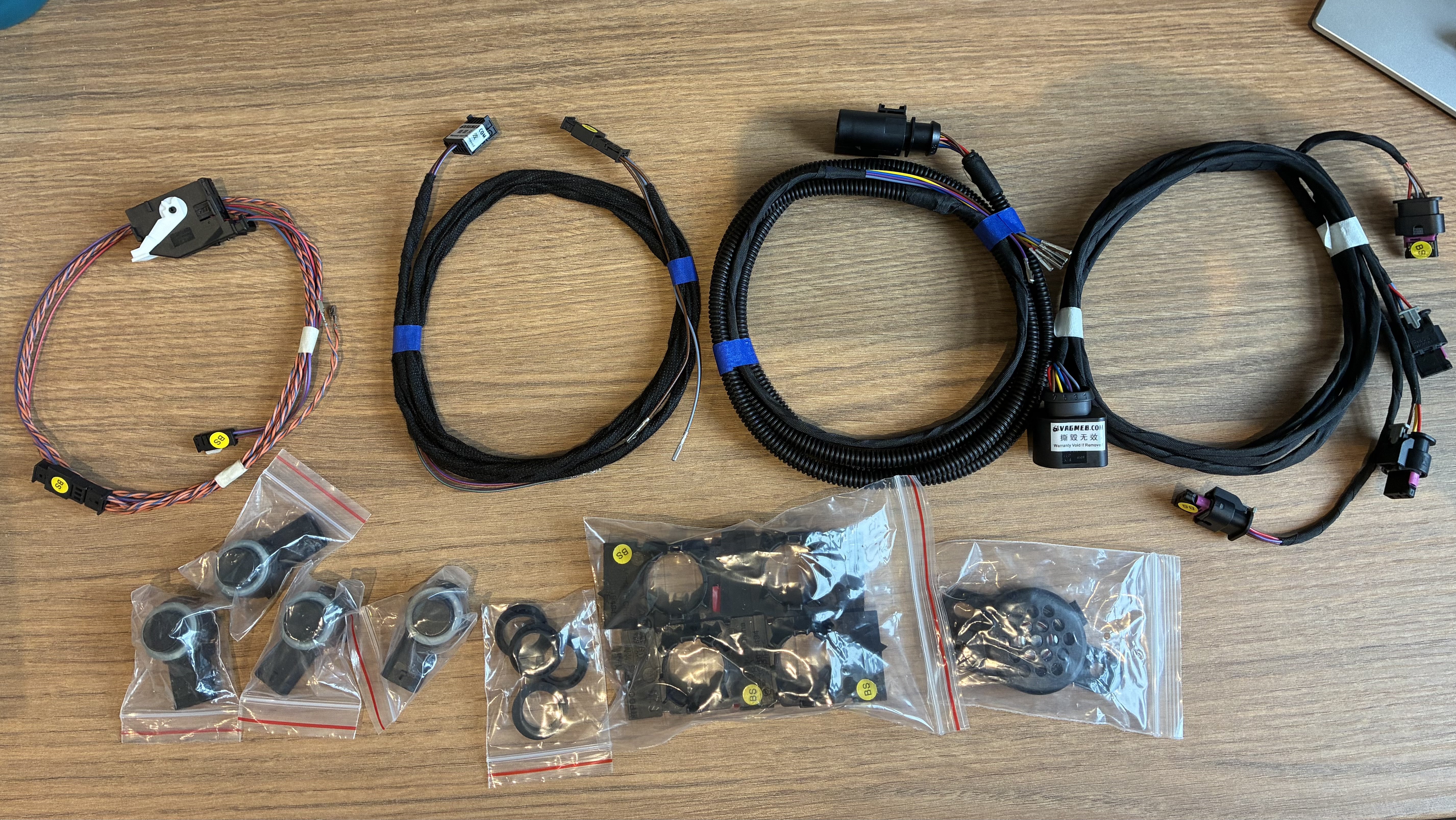
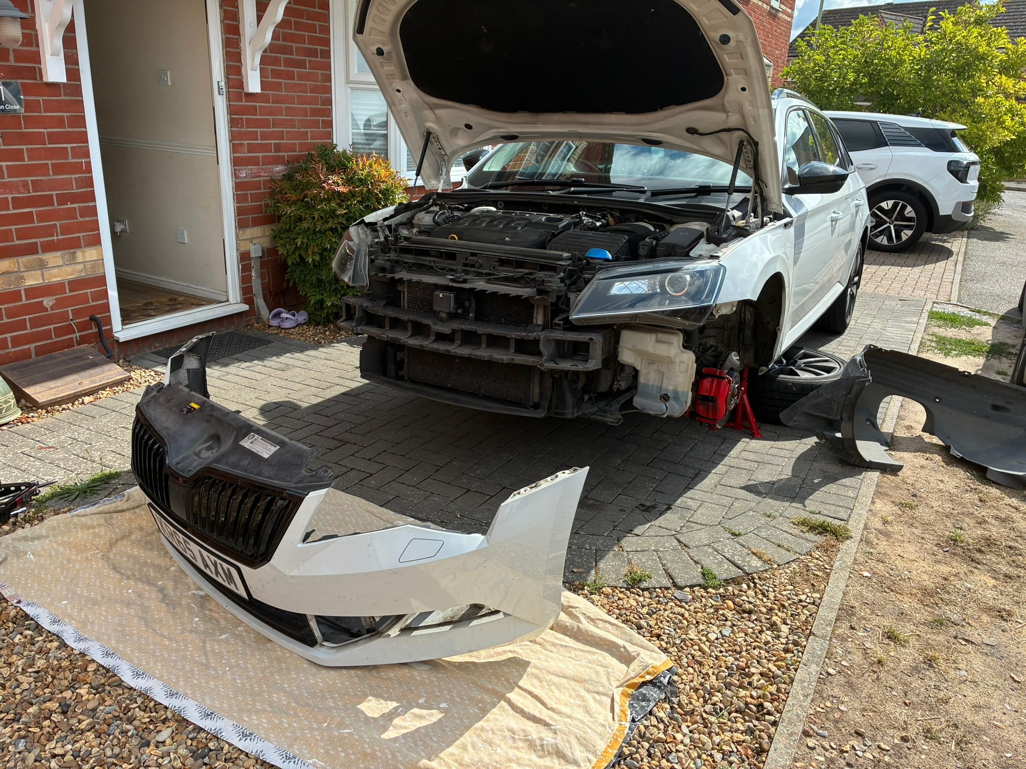
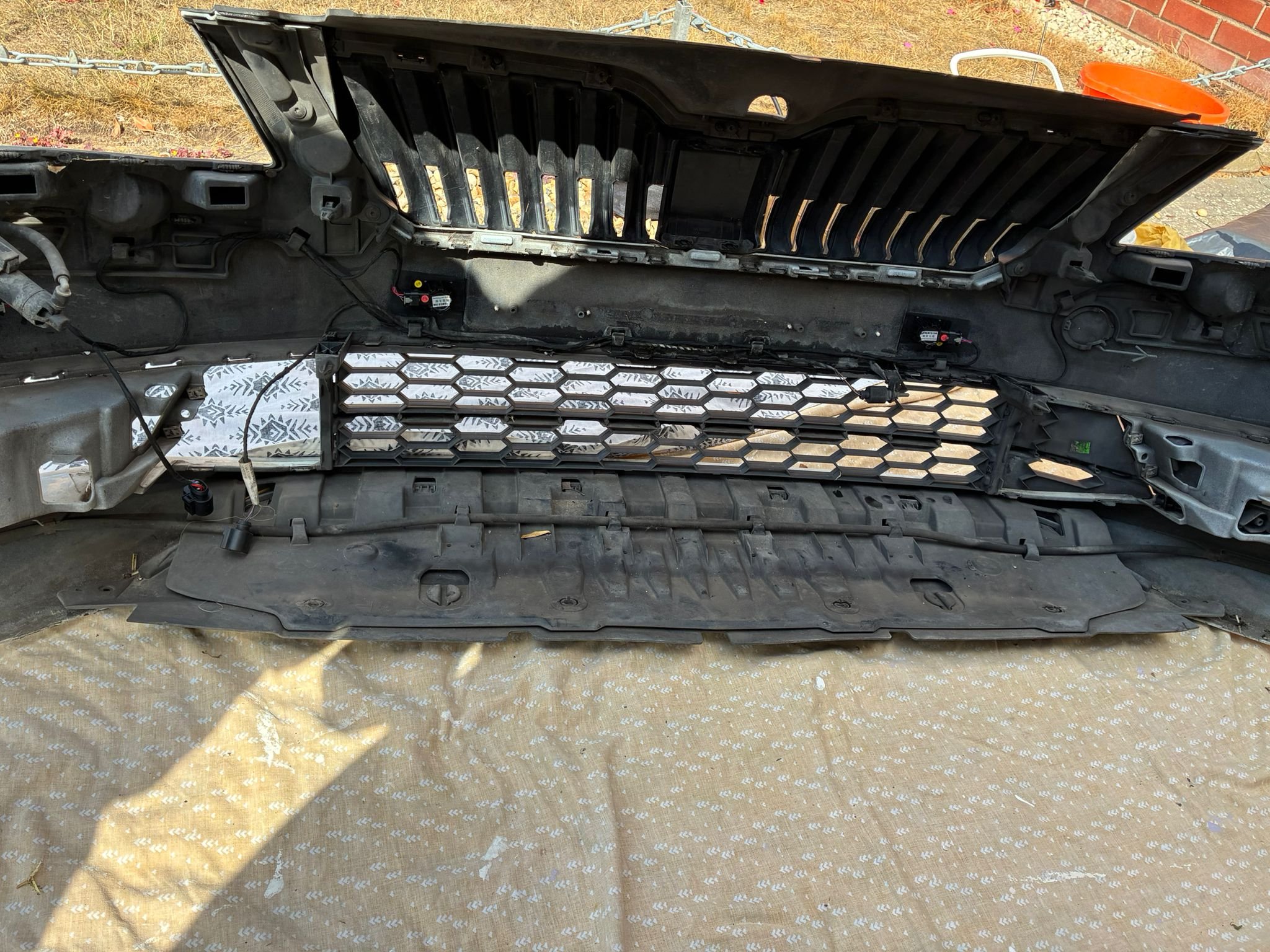
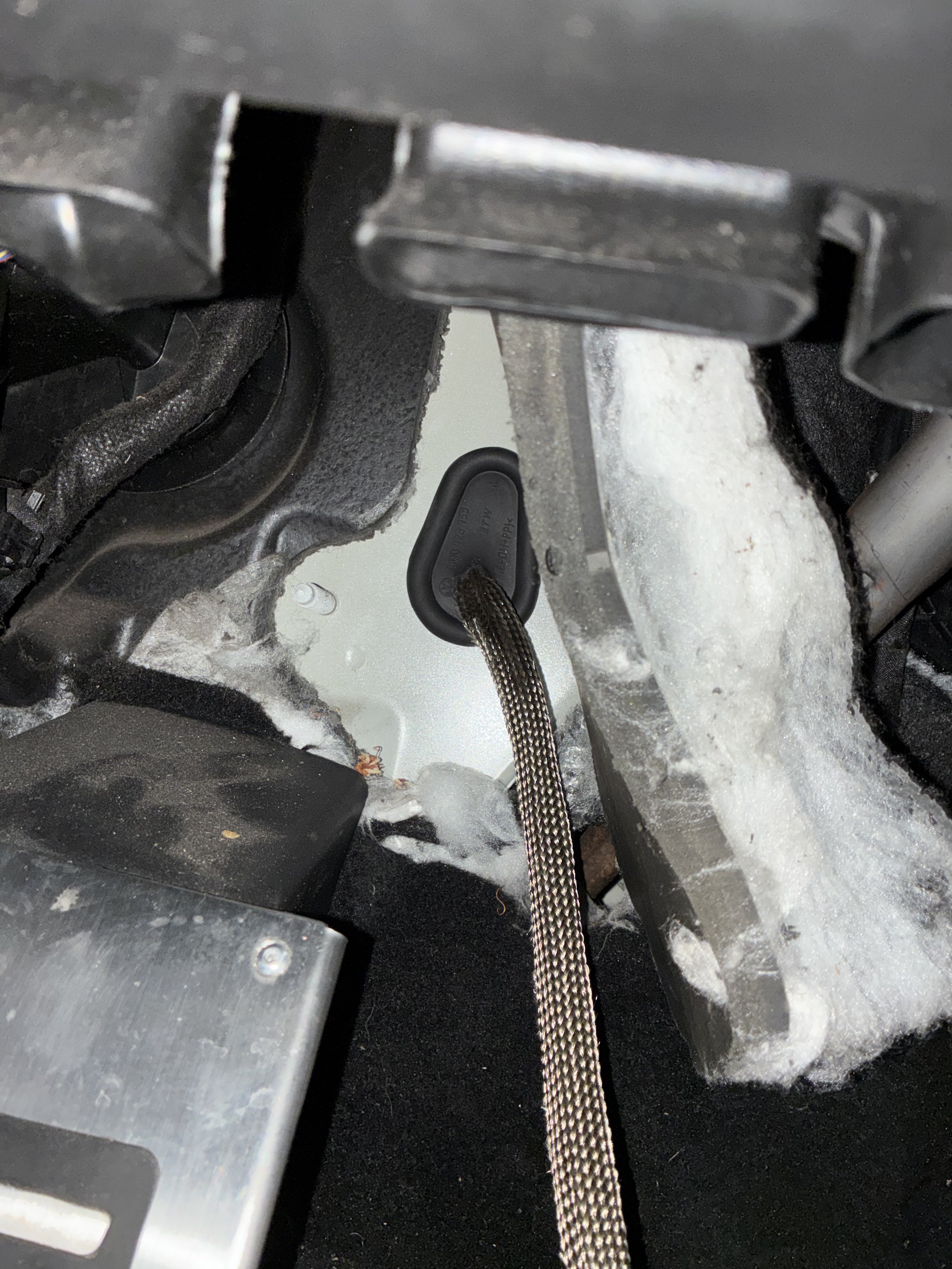
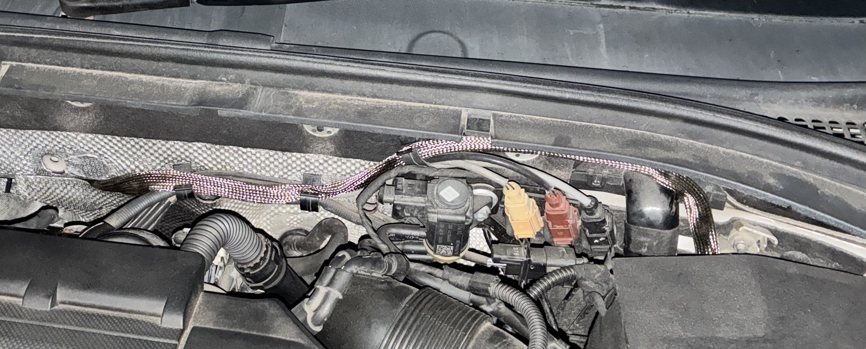
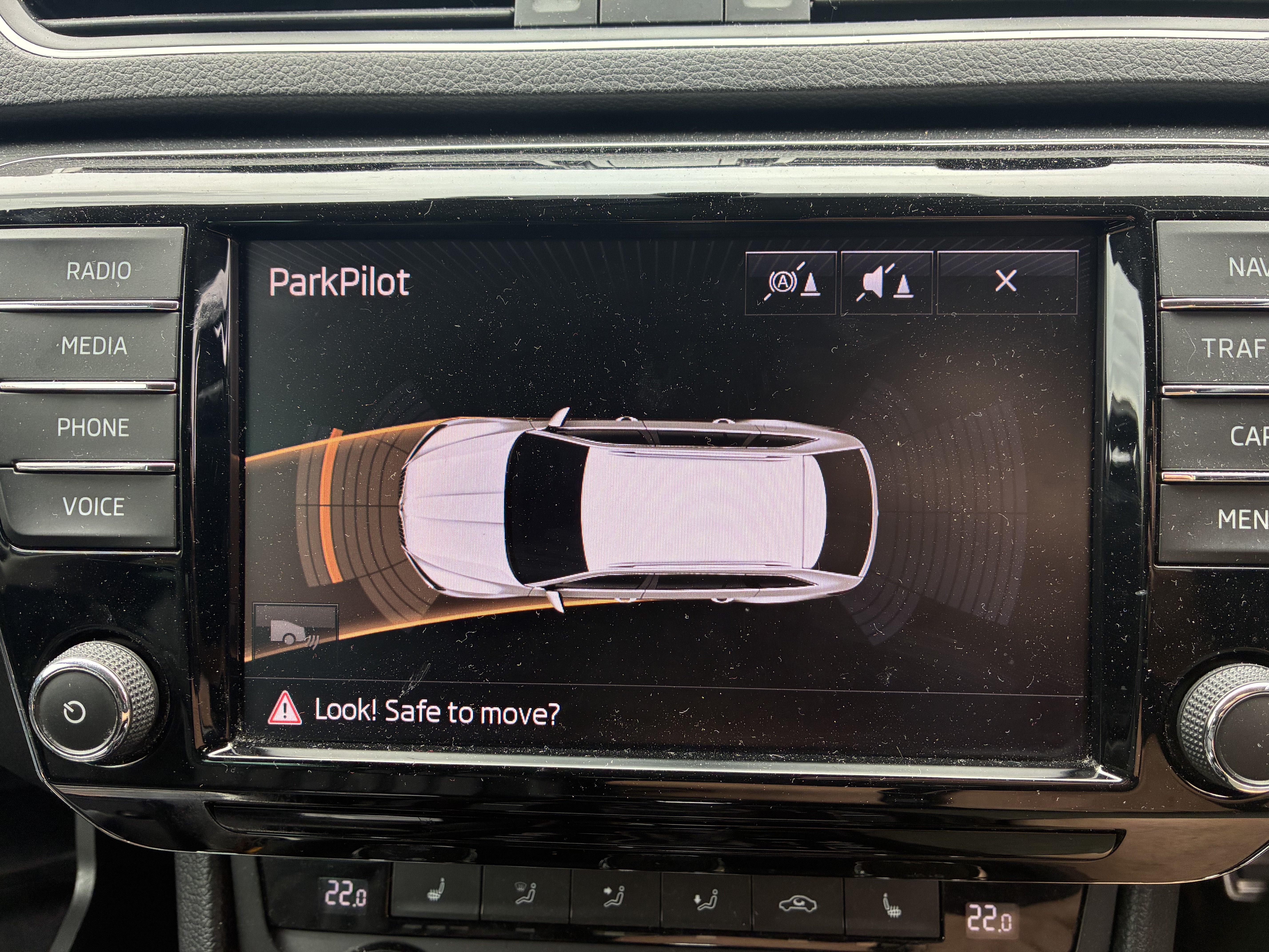
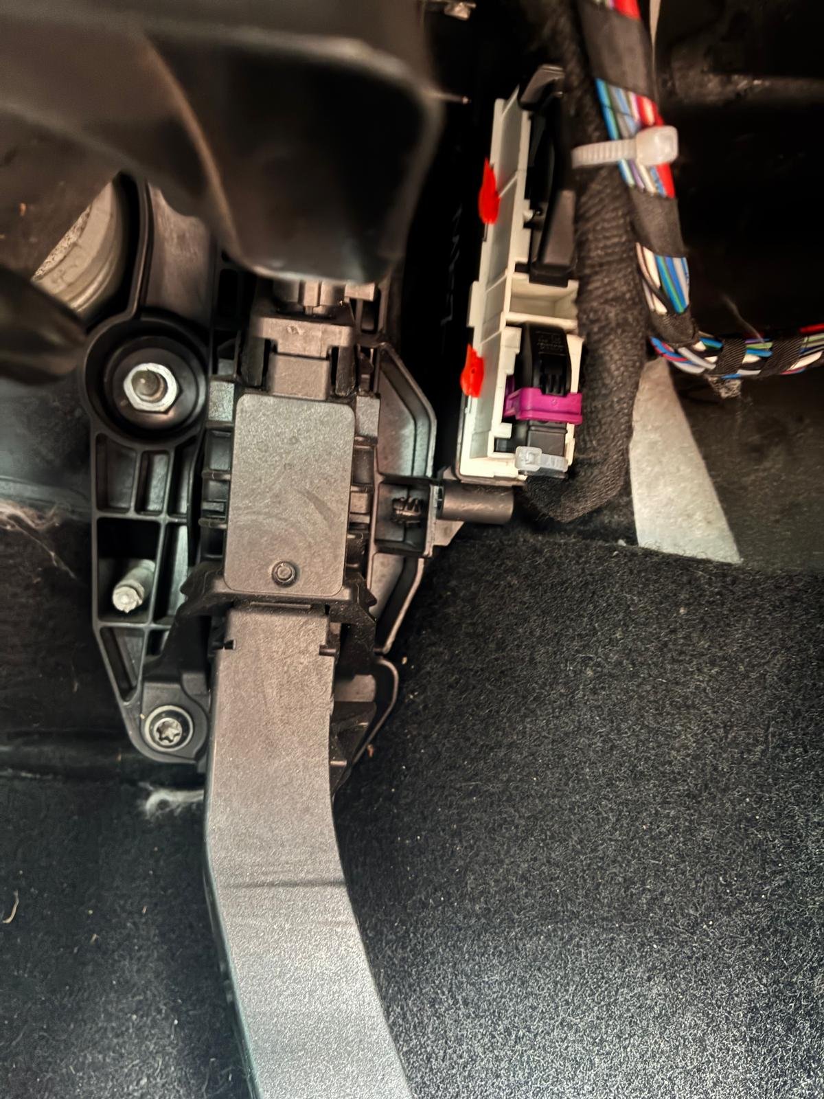
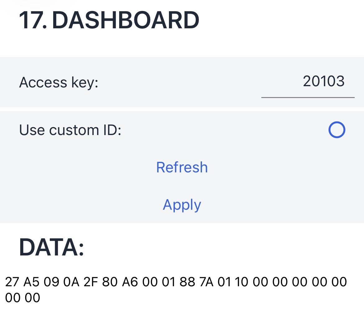
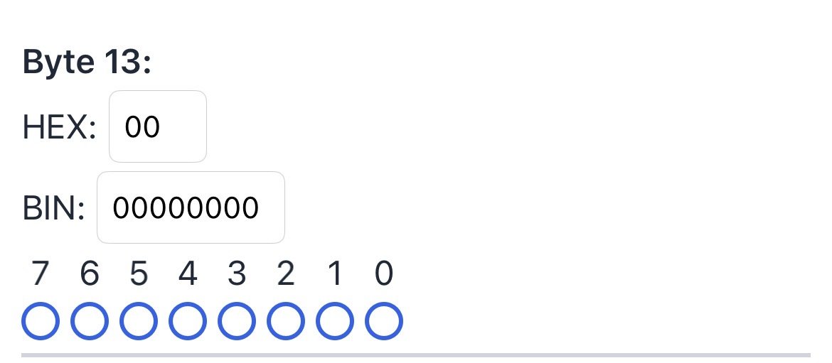
I thought it might be useful for others to have this information all in one place. I do not claim to be an expert but this is just my bumbling process of adding front parking sensors to my Superb. Parts list: Wiring harness, sensors and brackets - Kit is for LHD and the 18pin plug was missing - seller refunded the cost of replacement plug Tool for cutting holes in bumper (18mm) Cable to extend wiring harness (0.35mm2) - I ordered 3m of each of the 6 colours for the loom to keep it consistent, if you label them well you can do it all in the same colour 18pin plug (was missing from the kit) 5Q0972718A - This is available cheaper from Ali but i bought from UK supplier for speed. 8k Parking module 5QA919294B - sourced from eBay - find one where the donor car matches yours as closely as possible in terms of age and spec, and it shouldn't need any parametisation. Parking sensor switch (Find the part number for what you have currently plus the parking sensor button. Mine was electronic boot only originally so part number is 3V2927132Q) Colour Matched Spray paint - I had some left over from painting badges. Find your paint code for the perfect match. Cloth loom tape Heat Proof Conduit Possibly not necessary but I used some as a precaution. Wiring Diagram - Superb 3 8k Front parking sensor Wiring Diagram.pdf If you are not experienced in reading these, watch this to help understand them. @JR RS Guide to removing the front bumper Removing Front Bumper.pdf Seat Cupra guide to a similar retrofit Mostly similar but some coding is different. Firstly I laid out the wiring loom. This kit included the 26 pin plug (Which is part of the standard Rear only set up) but not the 18 pin plug for the front sensors. Some wires were already pinned into this plug. To remove them, slide the flat end open nearest the wires, then slide out the connector block. You remove the individual pins by pressing onto the silver part with a gentle tension on the cable. You have to do it twice as the pin comes out of the block. This kit also inlcuded some CAN wires, and the plug for the switches including some extra wires for that too. I removed the wires from that plug too. On this one there is a flap that opens (Under the warranty sticker) and its the same process for removing the wires. None of the cable colouring in this kit matches the wiring diagram. So I carefully traced which wire was which by looking at the pin positions on the plugs. I printed out the wiring diragram and relabelled it with the wires corresponding to my loom. As this kit is intended for LHD, I knew I would need to extend some wires. I used sleeve crimp terminals to extend the engine bay section of the loom (The one in the plastic conduit) and used the pins from the plug kit to terminat them. I continuity tested the wires with my multimeter before continuing just to be sure the connections were good. Then I wrapped the extended wires in loom tape. (In hindsight I could have fitted everything in reverse, so that the loom went down the drivers side of the engine bay, and I probably wouldnt have had to extend it, just pin the signal cables into the plug in reverse, or I could have ordered another male/female plug kit and just plugged it in to extend it) Next I painted the sensors. Rather than masking them up, I used the cutting tool to cut holes in a small carboard box and taped them into position using masking tape. Now to the install. As not all the parts had arrived, I installed before testing the kit in the blind hope that everything worked! First, remove the front bumper according to the guide above. The OEM positions for the sensors are clearly marked on the inside of the bumper. Drill a 9mm hole at the marked cross in the centre of the circle. Then use the cutting tool (pulling from the painted side inwards) to cut the neat holes. Fit the sensors with the sealing rings and clip them into the brackets. Offer them up to the holes. My outer two didn't sit quite flush, but in hindsight I may have put them on upside down! I found the AliExpress brackets had extra tabs on that needed cutting off for the brackets to sit flush. Finally, clean up the inside of the bumper withe some brake cleaner or rubbing alcohol so that they are nice and clean. Peel off the backing on the brackets and carefully position in to place. Be sure to get them as level as possible. Connect the wiring onto the sensors, making sure to push them until they click, and then push in the little tab to secure them. There is cable management moulded into the bumpers and the plug should end up near the plug for the temperature sensor. Note the colours of the wires for each sensor, and make sure they match to how you have labelled your wiring diagram. Now I started to route the next section of the loom through the engine bay, starting with the plug near the other half of the temperature sensor plug. I threaded it up past the washer bottle and along the side of the ECU. I made sure to avoid crossing closely to any large red cables in case of interference. I like to rebuild as I go, so at this point I got the front bumper back on and the car back on the ground. This is the point where I then struggled to find somewhere to get through into the cabin. There is a couple of grommets on the passenger side but I couldn't find my way through them. As my car is a DSG, I knew there would be a grommet in the drivers footwell where the clutch would be mounted. I pulled the grommet out and fed some stout wire up behind the heat shield to come out just under the scuttle. This is where I ran the cables through some heat proof conduit as they are crossing the back of the engine bay near to the exhaust. There is some convenient cable management clips that it slotted in to. Once in the footwell, I then routed the cables up and over the steering column area to emerge next to the PDC module which is mounted just above the accelerator pedal. Now to pinning the plugs. Remove the small storage tray from next to the steering wheel for better access. I removed the existing 26 pin plug from the module (Push the button then the lever pulls down) Cut the cable tie, and slid out the connecting block. On these connecting blocks, the pin positions are numbered at each end of each side, and its a case of counting along to the right position. To this plug, you add the wires for the front beeper to pins 2 and 10, ensuring you get them the right way round according to how they are pinned on the plug that goes into the beeper. You also add the two cables to go to the button, to position 16 and 17. Make sure you know which way round you have positioned them so you can put them into the corresponding positions in the plug for the switch. From here I routed the wire up and over the steering coloumn under the dash, and around the side of the centre console (One torx under a little cover towards the front, and then pull down on the panel to remove). Then its just a case of prising up the surround around the gear shifter, and releasing the red plug on the current switches, and the row of switches then pushes out from behind. Add your new pins to the plug to positon 4 and 5 (16 to 4, 17 to 5), slot the switches in, plug in and put the trim all back together. Now you can pin the 18 pin plug with the wires from the front sensors. Be careful to follow the wiring diagram carefully as the 18 and 10 are very difficult to distinguish and I wired it backwards initially. Then plug both the 26 and 18 pin plugs into your 8k controller. I got some errors initially as there is some coding required. Some was already correct but I checked the following: Module 10 - Byte 2, Bit 0 Module 10 -Byte 1, Bit 5 Module 17 - Byte 13, Bit 0 (Thanks to @Cairus for guiding me to this one) Clear fault codes and all was well. No further dataset or parameterisation of the module was needed. (I initally bought a newer module that gave me all sorts of errors, hence the tip above of finding one as similar to your car as possible) The last thing to do was tidy up the wiring with a few cable ties, mount the beeper somewhere up under the dash, and swap the modules. Removing the plastic pins for the module was one of the hardest things of this project. I had to use a fine screwdriver to push the centre pin out from beind, then pull out the outer pin. But finally all was in place, closed up and working well.