Leaderboard
-
SteveTheElder
FREEDOM20Points2,378Posts -
Lee01
FREEDOM11Points36,412Posts -

chills
Members11Points1,689Posts -
.jpg.5f5908b5afb5ed410c43d763df801089.jpg)
Evolution13
FREEDOM10Points2,490Posts

.thumb.jpg.9dd3f612ba7f13d10be5c518d3c8d255.jpg)


Popular Content
Showing content with the highest reputation on 01/04/26 in all areas
-
6 pointsEV AccessoriesEverlasting EV Screen Wash – The End of Screen Wash Top-U...Never top up screen wash again! The world’s first everlasting EV screen wash – specially formulated for electric vehicles. Ends refills forever. UK stock, fast delivery. Only possible on EVs! (April 16 points
-
2 pointsYou're good with "Paul you're over thinking it". You've never met me and yet diagnosed my tendency to jump to the worst case scenario and work backwards 🙂. You also get a thumbs up from my wife, who has never believed in loyalty. I've bought the Ring battery charger and it's on the car now doing its thing (or so I assume - the instructions are in those pictograms that are universally incomprehensible). Since the weekend (and I know it's only Wednesday today) the car has been starting as normal and it's had two decent runs of 40 miles or so the last two days to the vet - for those who think £100 for a battery is a lot of money, my advice is don't get a Cocker Spaniel no matter how cute they look. So I'm going to do my usual thing of crossing fingers, stick my head in the sand and hope it was "just one of those things". It is due to go in for MOT and service in the next few weeks so if nothing else goes wrong between now and then I'll get them to test the battery and charging whilst it is with them - they're a local firm that I've been going to for 10 years or so and I can trust them to be honest.2 points
-
2 pointsI Bought a new 1.5 DSG Scala Monte Carlo in 2021 and changed to a Karoq in 2025. It was one of those decisions you make in life that you think, did I do the right thing? Loved the Scala and wouldn't hesitate to get another.2 points
-
My Intelligent Octopus Go tariff has reduced to 5.2p overnight & smart charging and 28.83p peak. With the new ID.3 on the drive giving 3.9 m/kWh average so far I'm looking at less than 2p/mile on fuel costs.2 points
-
2 pointsI've just traded in my 68 Plate Octavia 1.5 TSI SE L last week for a 22 Plate Scala 1.0 TSI 110 SE L. We only had few payments left on our pcp deal and had quite a bit of positive equity on the Octavia. We started having a look around. There were no octys in our price range so looked at a Kamiq, it was a 1.0 TSI DSG, it was nice enough to drive but liked the Scala more. The Scala is easier on the eye than the Kamiq. The 1.0 TSI performs well enough. Mainly short cummutes to work and the occasional longer journey. The Scala is very good to drive whilst not as spacious as the Octavia it certainly ticks all the boxes. The virtual cockpit is nice, the 9.2" infotainment system and interior is very nice. We have the KESSY system, reversing camera and it also has a tow bar. That will be handy for a bike rack.2 points
-
2 pointsIt's not DPF regen, i've checked the status once it had high revs and it wasn't in regen mode. The values I am getting of the sensor are default rubish values. If I unplug the sensor the stay the same, so I dont think I'm getting anything of the sensor. However, I did read somewhere that both the sensor and the alternator wires use the same line to enter the onboard computer. Apparently thats how LIN communication works. If the alternator is feeding rubish through the wire then it might as well distupt the signal the sensor is sending. Unofortunatelly, the wire from the alternator is hard to reach without dissasembling stuff, so I cannot double check his claims.2 points
-
Has this been fixed? Do you have a print out of the alignment with the figures on them? Have you seen the bent part of the axle? Thanks. AG Falco1 point
-
1 pointIm from heartfordshire, currently owning fabia axr estate 2006, a4 b6 avb, seat Leon mk4 2.0tdi and impreza sti 20031 point
-
Latest replay from Skoda Customer care .. we shall see what transpires >>> Dear James Thank you for your response and for clearly outlining your ongoing concerns. I do understand your position and appreciate that the matter cannot be considered resolved while you remain unable to tow without the Proactive Passenger Protection System activating, and I acknowledge your comments regarding the vehicle being unfit for purpose until this is addressed. I would like to confirm that I have since contacted Chris at Bristo's Škoda Ipswich, as advised. Chris has confirmed that he is in direct contact with yourself regarding this matter. At present, he has advised that the vehicle has not yet been booked in for full diagnostics to investigate the towing concern. Chris has also made me aware that he is currently liaising with his Parts Department for further assistance and guidance. Once the necessary arrangements have been made on their side, he has confirmed that he will be in touch with you directly to arrange a booking for the vehicle to be fully diagnosed. At this stage, as the vehicle has not yet been booked in, there is unfortunately very little further assistance I am able to provide until diagnostic work has been carried out. However, once the vehicle has been seen by the retailer and further information is available, I will of course be in a position to review and support the matter further as needed. Please rest assured I will remain available should you require any additional support once the next steps are confirmed. Kind regards Samantha Joseph Customer Relations Manager T: 03330 037 504 E: [email protected] Škoda UK Yeomans Drive Blakelands Milton Keynes1 point
-
Well done you for doing all this. The issues you describe are exactly the same as what I experience when I'm towing. Please keep posting any updates you have on pursuance of obtaining the necessary coding and rectifying the situation. And thanks. Stuartie.1 point
-
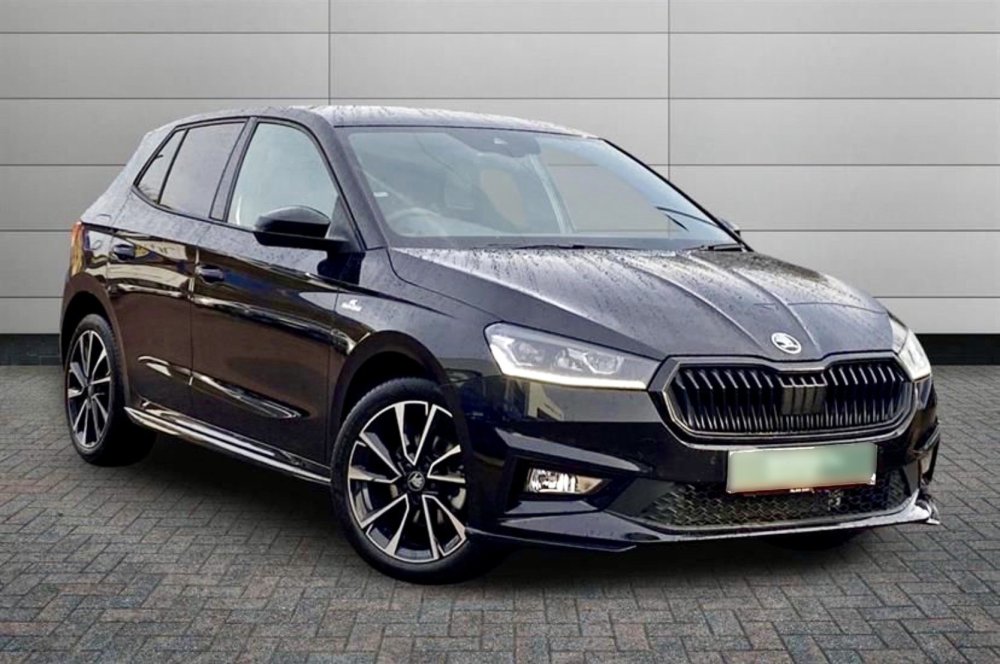
1 pointHi Guys, just taken delivery of my new baby, a Black Fabia Monte Carlo, exactly a year old, with just over 3k on the clock.
 1 point
 -
If we ever get to £0.00 kwh per unit the standing charge will be £2.50 a day.1 point
-
Thank you kind sir and apologies for the hassle. I looked through the long list and there were about three that seemed possible but I didn't want to litter.1 point
-
Eon Next just asked if i want to sign up for their Power Up / Power Down Scheme. So they are introducing what others already do. I use so little electric during the day and between 16.00 - 20.00 that i can not power down. Plugging in using the 3 pin lead for 2 hours is not going to be Powering up much. 5-6 kWh max..1 point
-
Your post is now in the Skoda Scala forum. Hopefully a fellow owner or other member will be along to help soon @scalaboris 👍1 point
-
Its handy when you realize its raining and a window is down but its not so good when it happens as you walk away from car and the key was pressed in my pocket. Came back to carpark with all windows down. Luckily nothing in car worth taking. Alasdair1 point
-
It's a really useful feature on those rare hot days!1 point
-
1 pointYes, thats what the mechanic stated. He said that once the electronics was disconnected from the circuit that everything else started working. He also said he was not able to find only the regulator for purchase, and therefor the complete alternator should be replaced. The problem is also he quoted the valeo regulator at 600 eur. I'll have to check if he will be willing to do the work with a refurbished one and still guarantee for the work.1 point
-
1 pointThe alternator also contains extra electronics communicating via a LIN bus which is used by the battery management system to control the alternator output voltage. This electronics could be faulty - it wouldn't be the first time a "smart" alternator has failed in this way.1 point
-
I do like the Superb. Had a test drive in one a few years back and very nice luxury car but went for the Octavia MK2 1.6tdi instead as it had manual box not dsg. we were needing a car for work as well as play but seriously considering one after my MK2 diesel dies. Reckon on petrol this time as not doing the long mileage and short runs are death to the DPF. Would love the VR6 but reckon I would be in big big trouble and doubt I could afford a MK3. From memory they are slightly longer than the octavia. Good luck with the search Alasdair1 point
-
Might be worth either getting them to charge battery or borrow a known good one/get garage to jump it and get it rescanned. If its the battery then your needing a new one but it could be wiring issues/earth issues/BCM ECU etc which may be expensive and difficult to diagnose. The speaker may be just a broken wire in door The heated seat I think its the left seat according to code. It may be the connection has been pulled under seat perhaps when cleaning etc. Read that the drivers seat will stop as well. Alasdair1 point
-
EGR cooler issues can cause what looks like blocked DPF and failed regens1 point
-
1 point
-
1 pointOccasional high revs at idle could also be the normal DPF regen happening? Since you can talk to the battery sensor then the alternator is clearly not blocking the shared LIN bus, so I go along with replacing the battery sensor.1 point
-
1 point
-
1 point
-
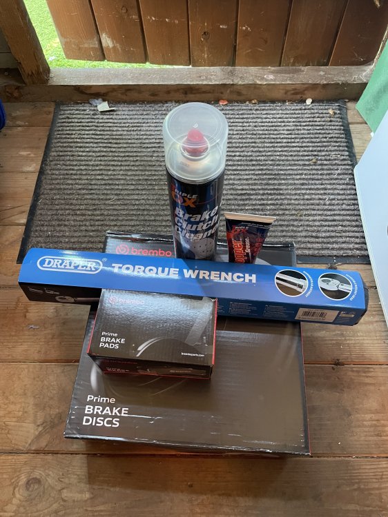
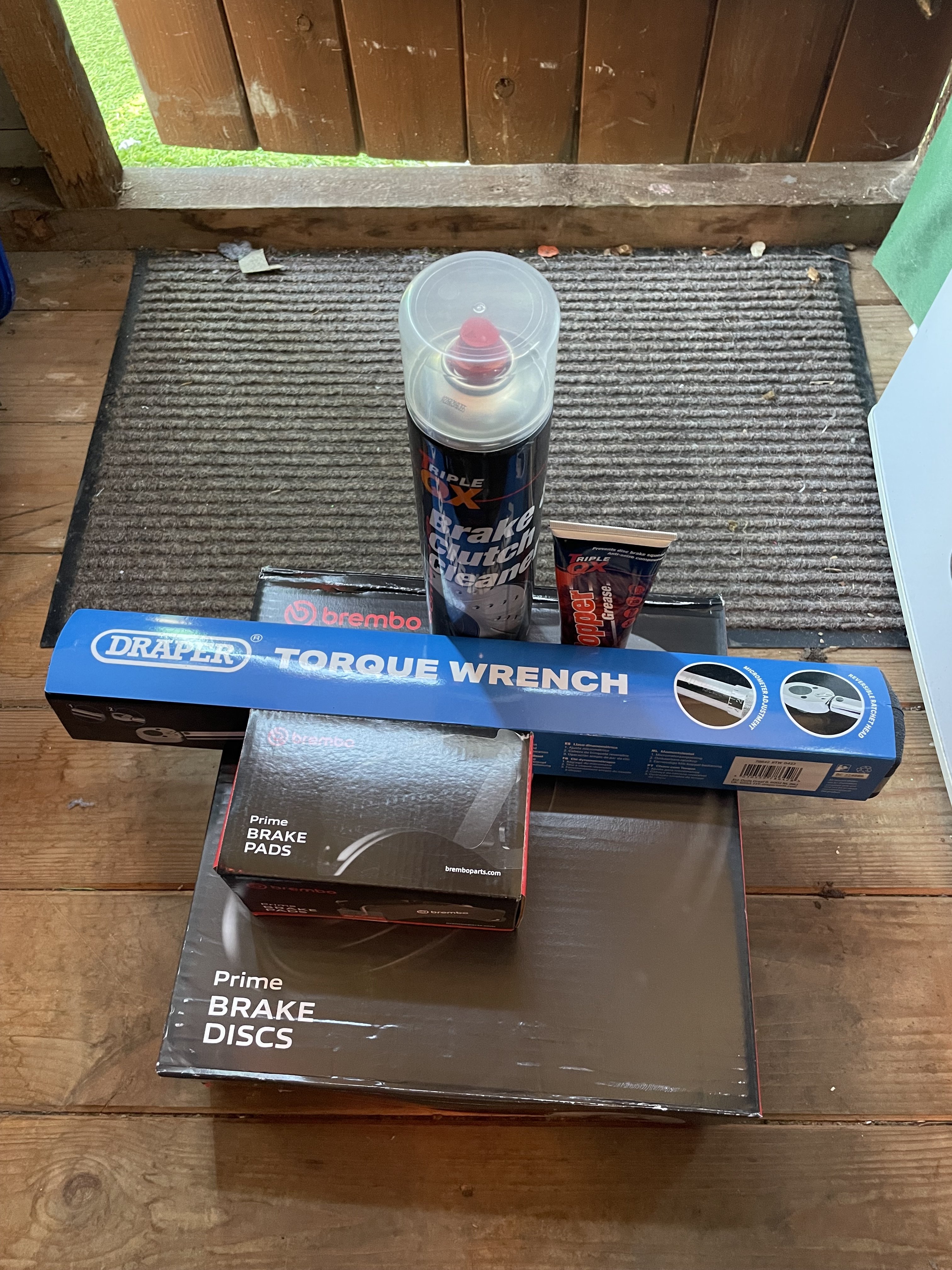
Thanks. I’ve got Brembo. Should be doing them this weekend hopefully.
 1 point
 -
1 pointIf its jumped from 3/4 to full I would suspect a sender fault or wiring short. From memory on modern vehicles the lower the fuel the higher resistance at sender hence a short will be zero resistance so show max. Not sure where the tank is but worth checking wiring to sender in case its damaged/worn. Might be worth getting it scanned in case it pings something up. It also depends if the signal from sender goes through the BCM module or direct to cluster. Alasdair If its jumped from 3/4 to full I would suspect a sender fault or wiring short. From memory on modern vehicles the lower the fuel the higher resistance at sender hence a short will be zero resistance so show max. Not sure where the tank is but worth checking wiring to sender in case its damaged/worn. Might be worth getting it scanned in case it pings something up. It also depends if the signal from sender goes through the BCM module or direct to cluster. Alasdair1 point
-
1 pointYes they have to rise. But that will be at the end of the Fixed Tariffs if you have that. Today to fix Smart Drive Next is 8 pence offpeak & Drive Next 9 pence for 12 months. PS, we as in the UK does still use Gas Plants to generate electricity, we as in Scotland have one remaining gas plant and 1 nuclear plant. Both will close at some point. The Peterhead plant is one of the most polluting facilities in Scotland. No.1 one most polluting now i think. Funny not funny really, that is where they want Carbon Capture to be and take Carbon from elsewhere. Yet right now they are not collecting there and piping out under the sea into where they took oil and gas from.
 1 point
 -
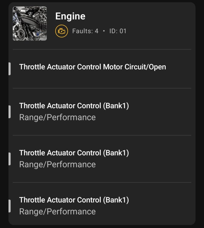
1 pointJust for info, I have DNFE 2021 with 77k km, My throttle body just died. I found on the internet 3 cases the same modification of the engine EA888 gen4 with same problem. The car is in limp mode 1500rpm max. Errors are P2101 , P2100 and P0638. I`m waiting new throttle body to be delivered from the local VAG store is 568 euro, 20 euro gasket and four new bolts 1.5 Euro per bolt.
 1 point
 -
Hehe yes, the oldest swinger in town, I've got some platforms somewhere....ah, I left them in the boot of the Capri when it was crushed ;)1 point
-
Yes this is what I will probably do I really don't need sports anything on my car ;)1 point
-
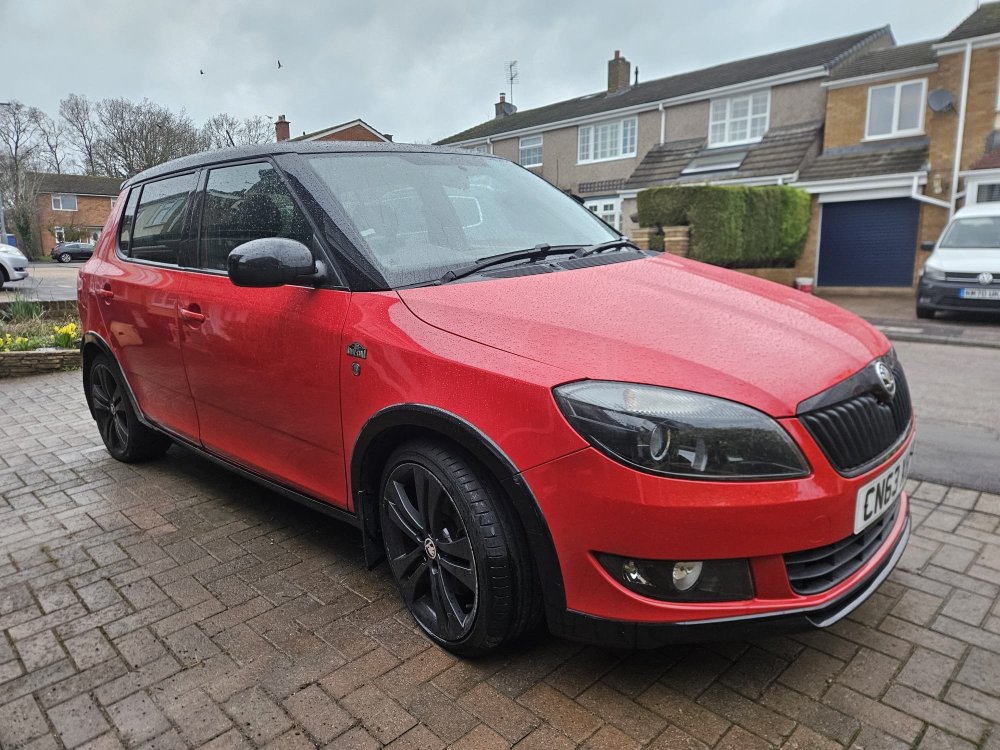
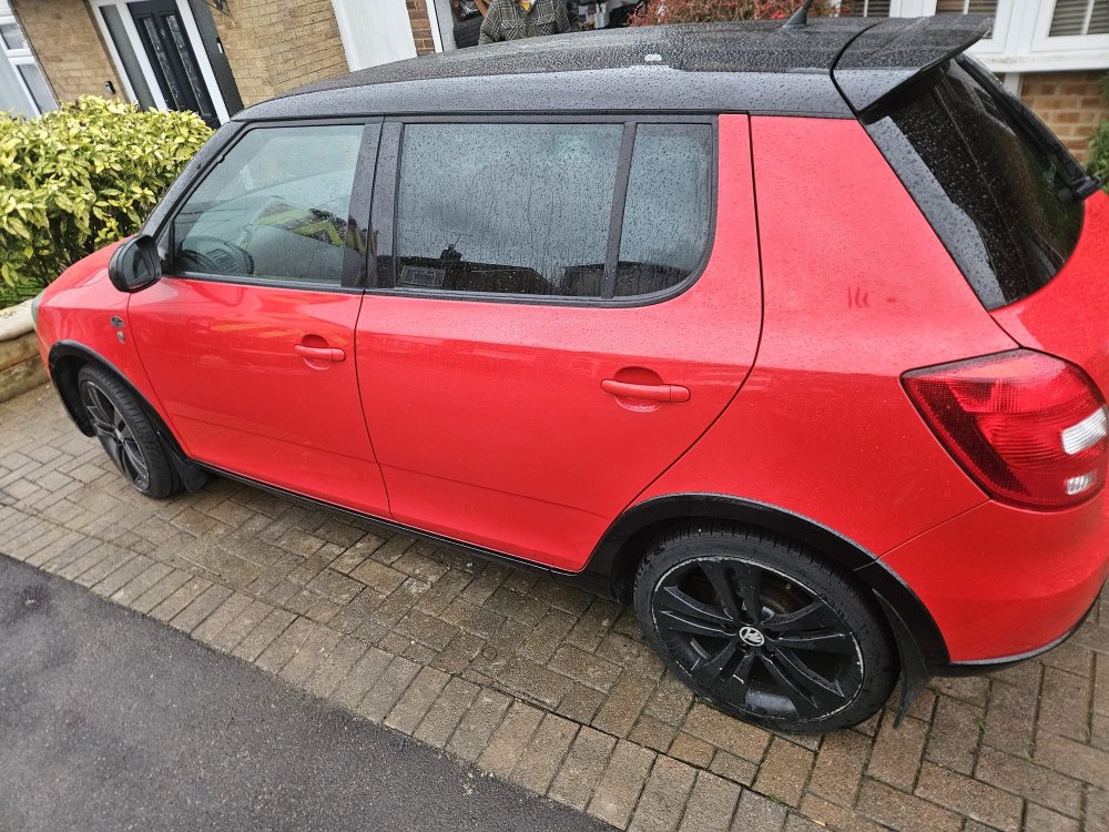
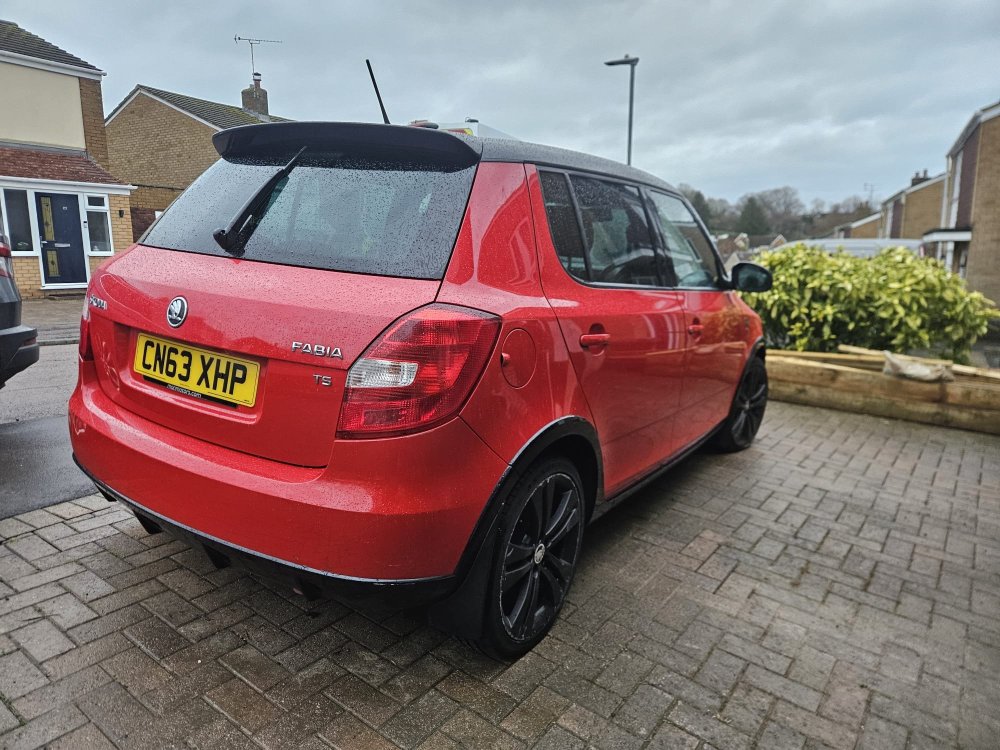
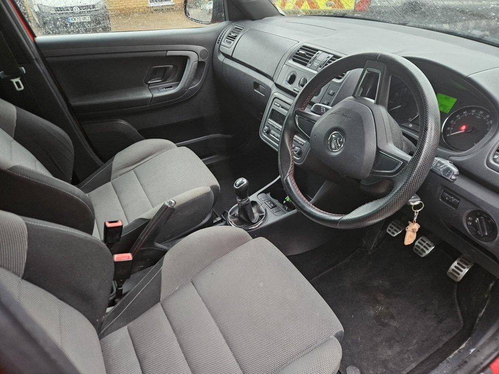
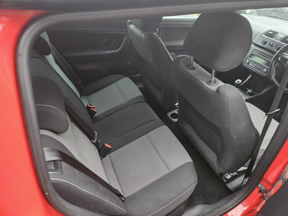
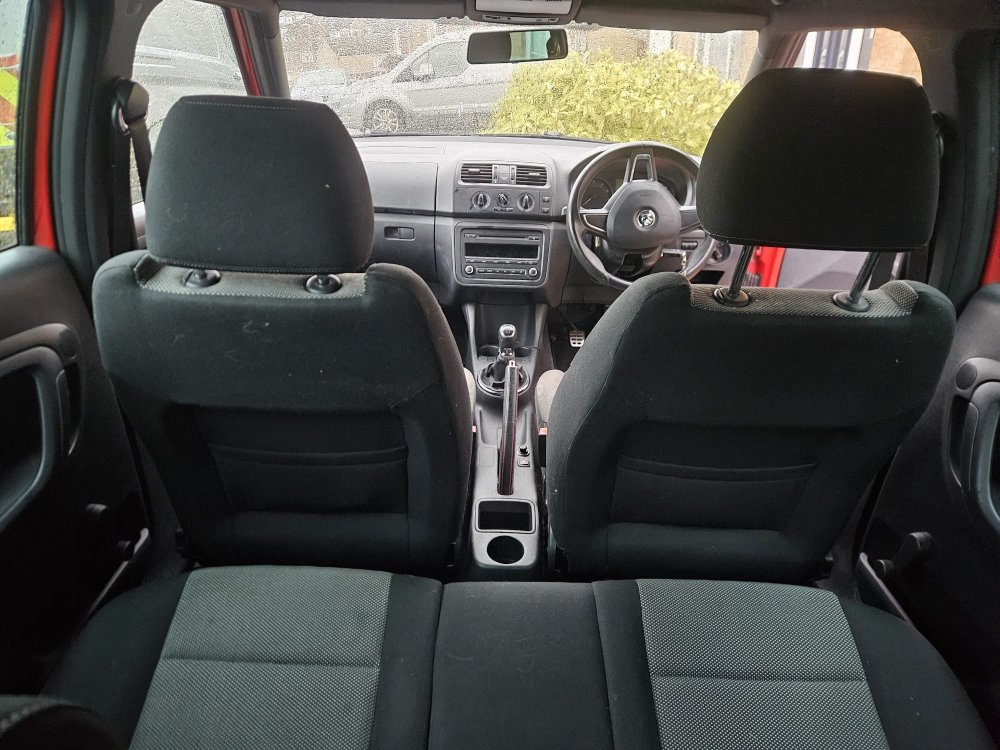
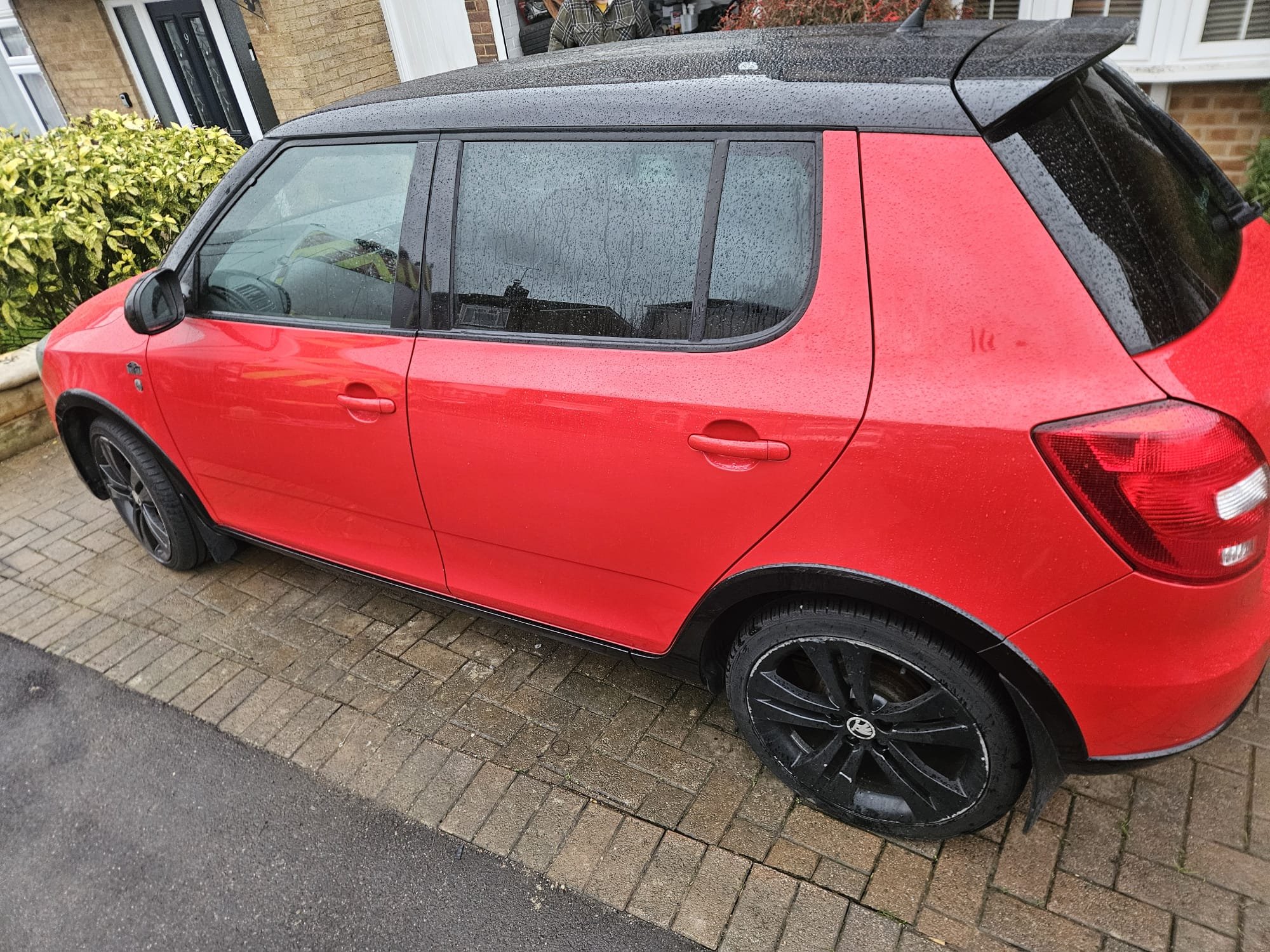
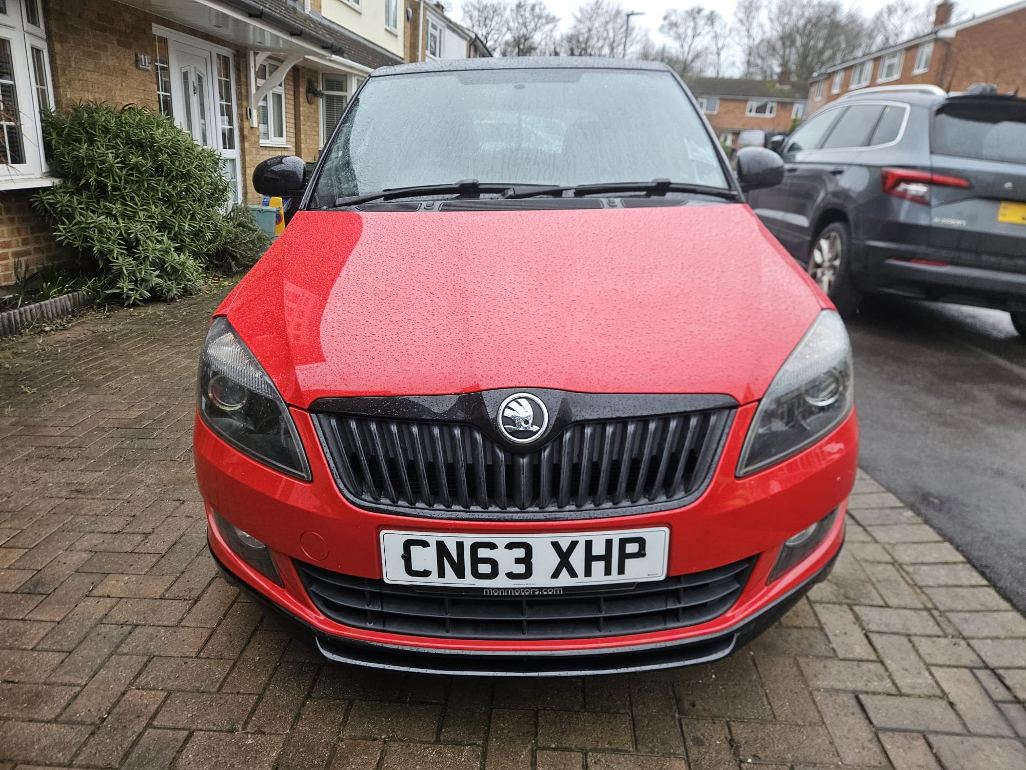
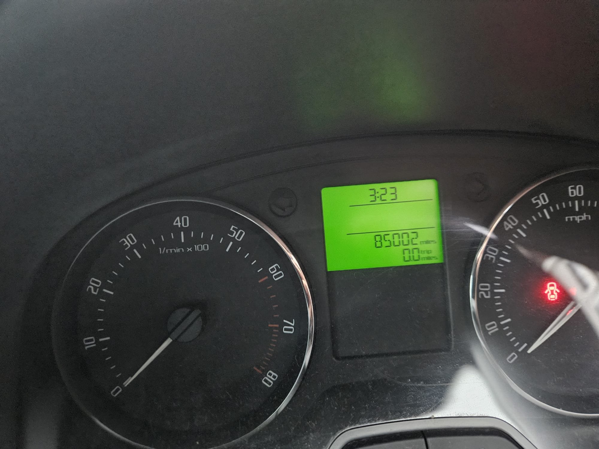
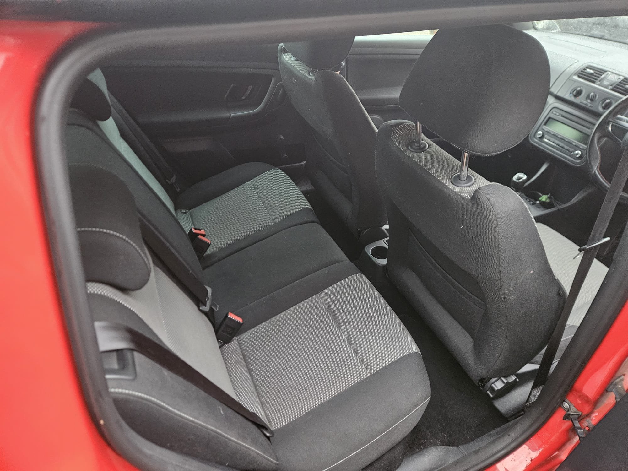
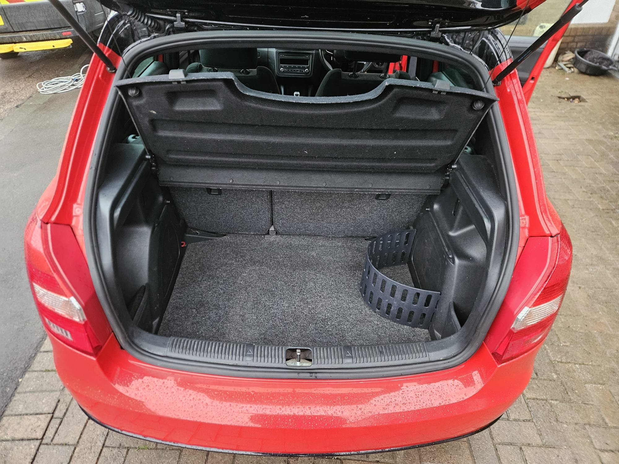
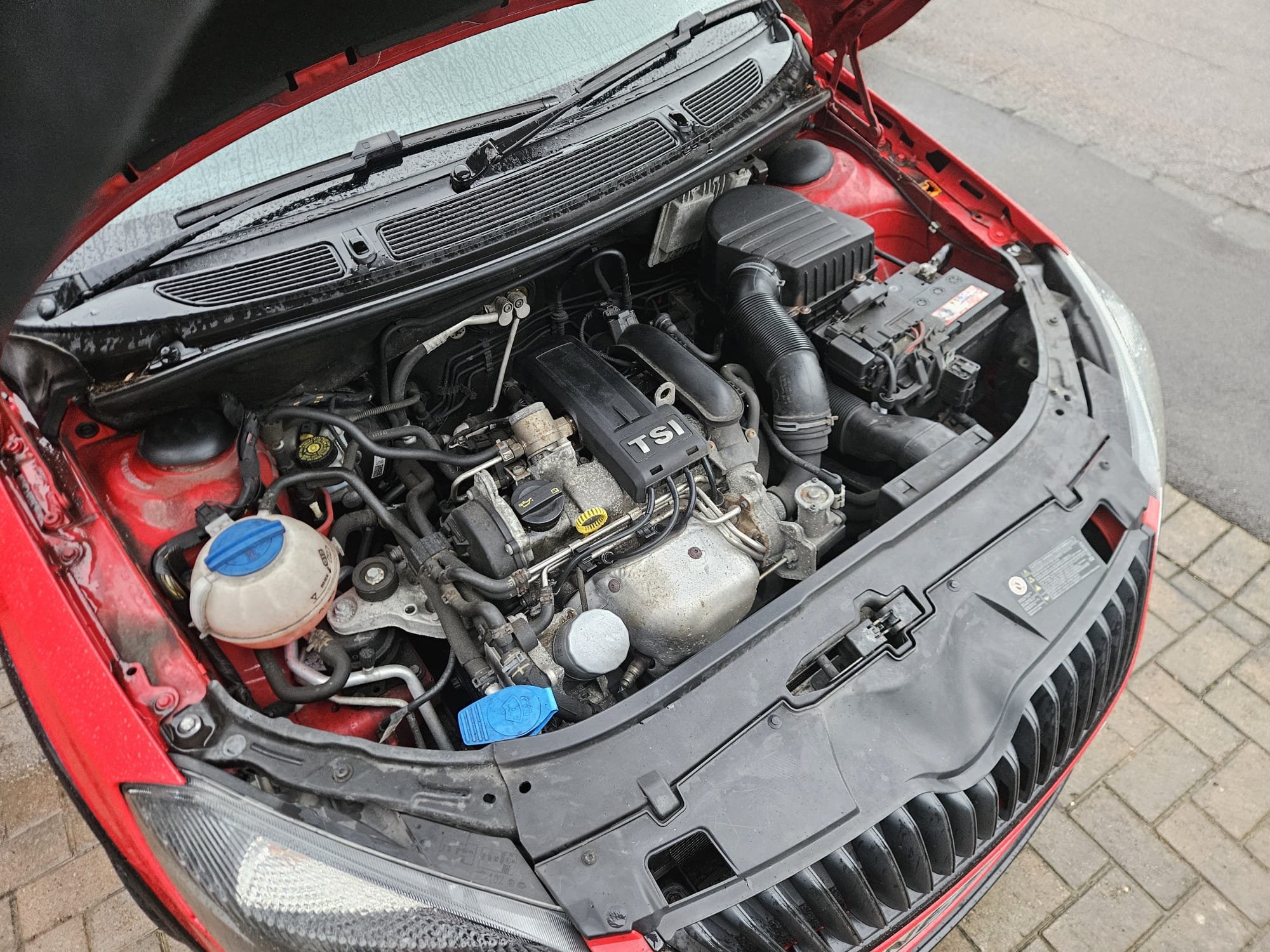
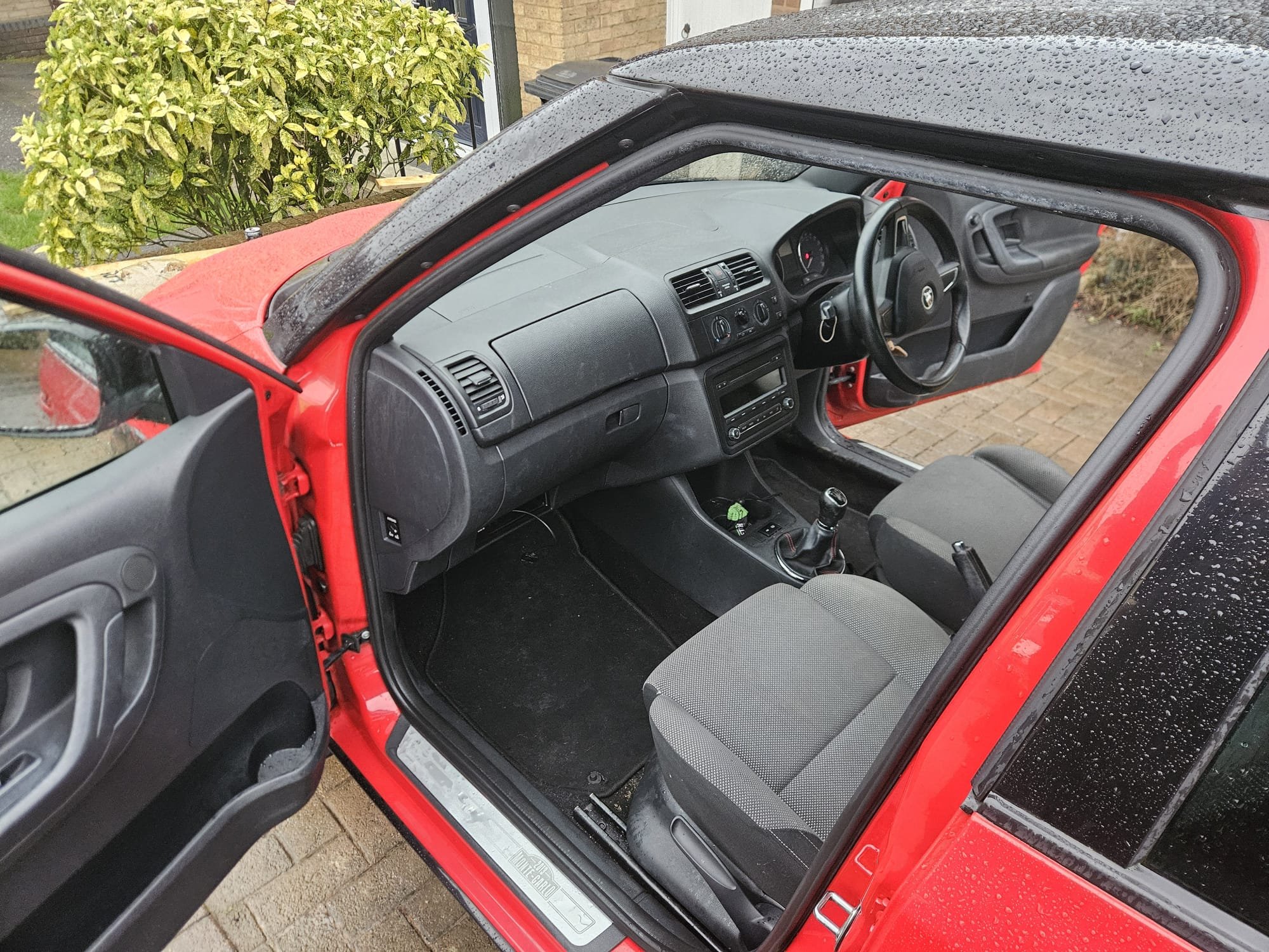
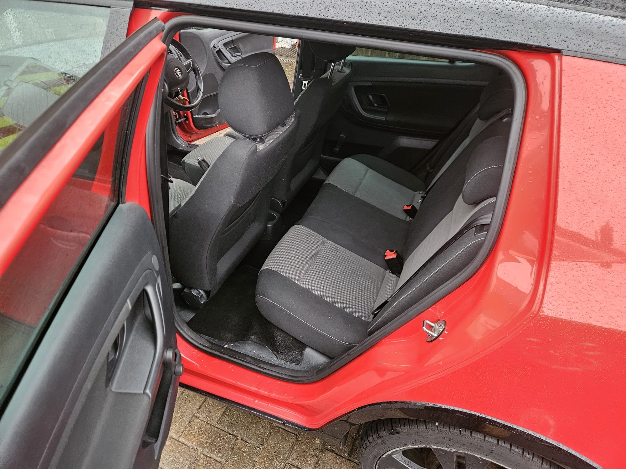
This is my daughters Fabia Monte Carlo that we purchased from a Briskoda member in January 2021 with around 25k miles. It was Cat C recorded in 2017 with front o/s wing and suspension damaged and subsequently repaired to a high standard. I have an image of the damage and the receipts for repair parts. The car has now done around 83k miles and has been serviced annually - with all the invoices present - MOT until August. It's a great car, goes well and is quite economical, whilst having good performance. Generally it is in nice condition - the wheels could really do with a refurb and we have just replaced the coil pack/leads/plugs. She has now purchased a Kamiq SE DSG as she was spoilt by driving my Karoq and Fabia vRS, both with DSG. Price is now reduced to £2350 o.n.o John Thomson Tel: 07860 208007 Car is in Hemel Hempstead, Hertfordshire.


 1 point
 -
A 1.5 TSI and DQ200 7 Speed Twin Dry Clutch DSG. It has no more BHP or Torque than Mk2 Fabia vRS had, & less bhp that the Polo GTI 1.8 TSI 192bhp that followed the Twinchargers had. There the Manual had 320 Nm and the DQ200 DSG limited to 250 Nm.1 point
-
Is there a cat before the dpf. If its clogged it would explain continuous regen but lack of airflow can stop the soot being removed. Not sure how you check. I would assume a fault code but perhaps not. Alasdair1 point
-
1 point
-
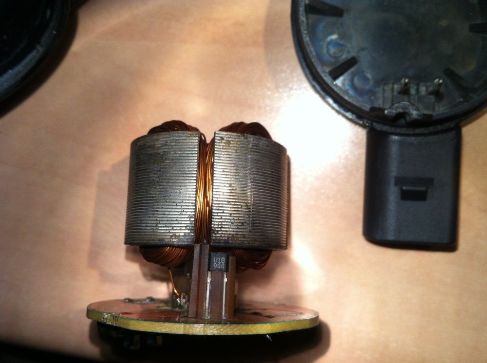
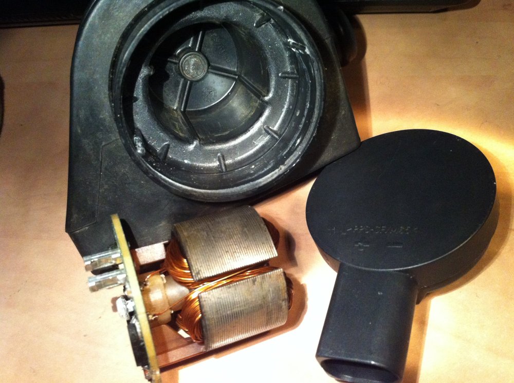
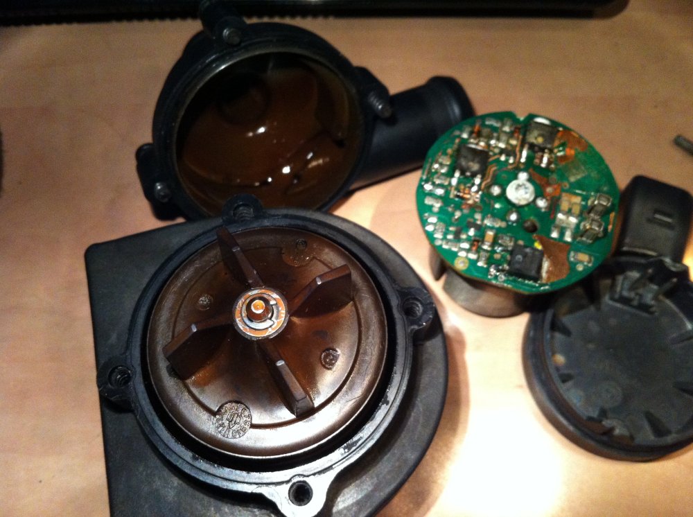
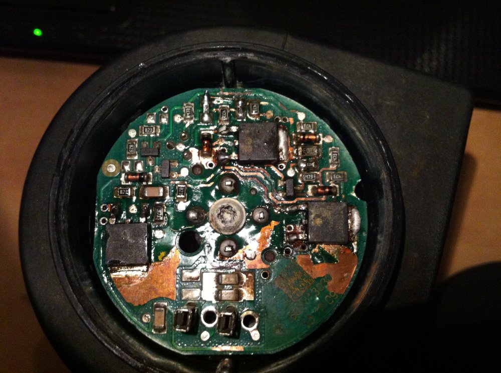
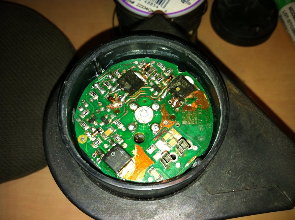
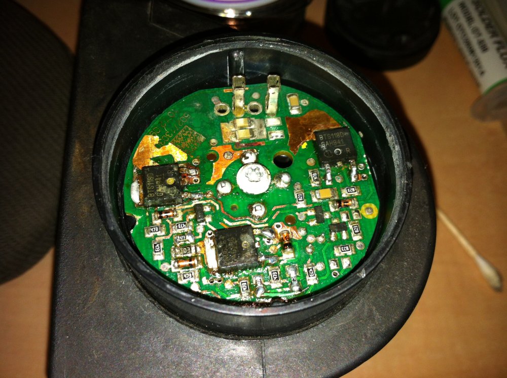
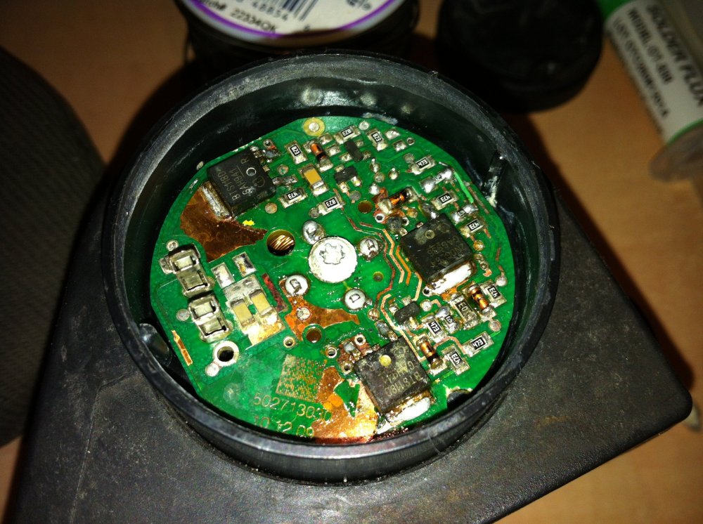
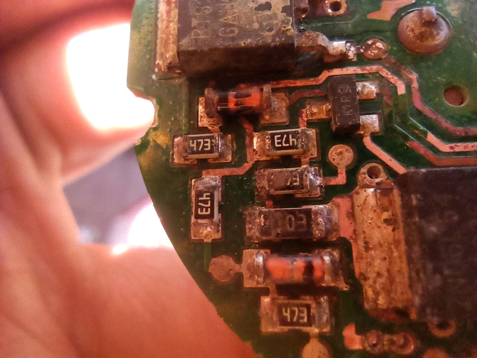
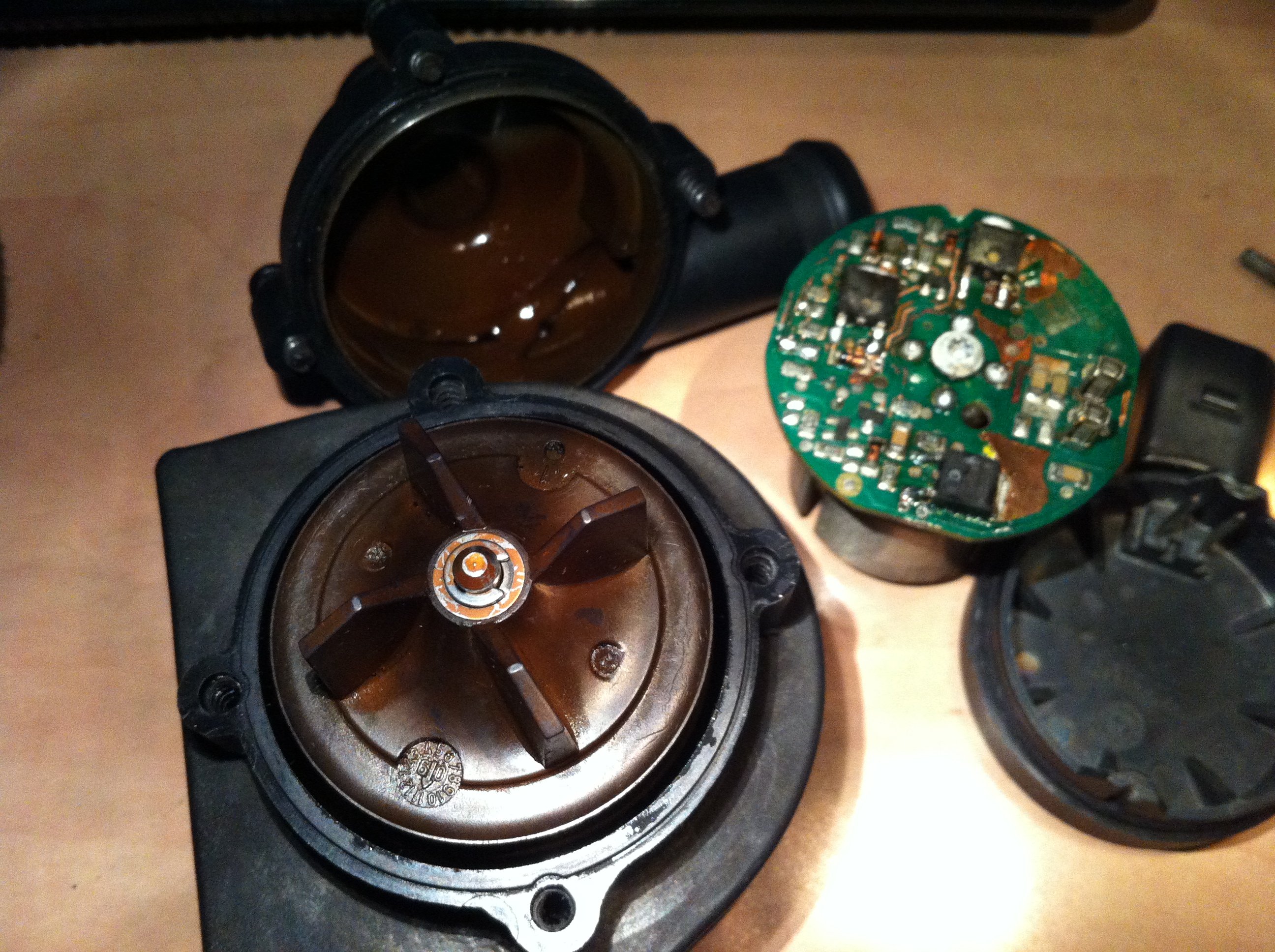
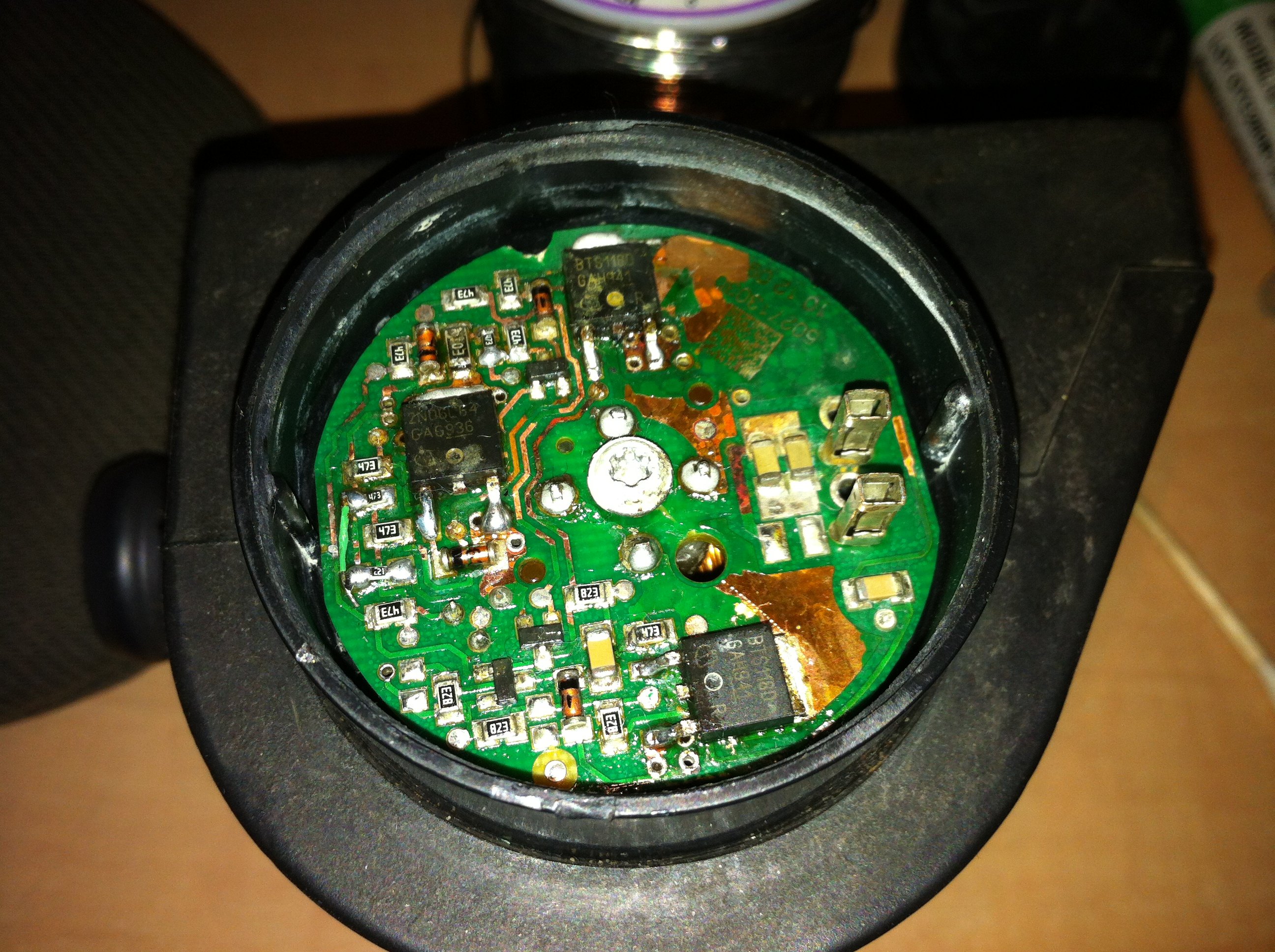
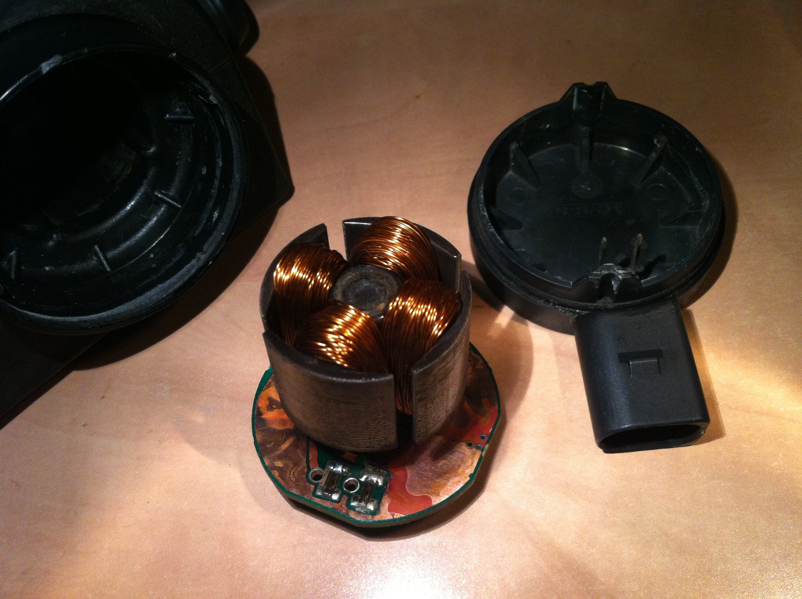
The auxiliary coolant pump, AKA turbo after run electric coolant pump, parking heater, on a 1.8 TSI VAG engine did not work. part number 1K0965561J I removed the pump and applied 12V to it but nothing happened. The contact on flat side of the plastic molding is the positive. I opened the pump by prying and pulling out the bottom piece where the electric plug is, it needs to be pulled out, it can not be twisted. I discovered a PCB inside and it was wet and full of corrosion, I cleaned it with alcohol and toothbrush and tried 12V again and the motor jumped but didn't continue rotating, every time I powered it the rotor jumped to a position and held itself there, what does that mean? maybe only some of the 3 mosfets were firing? I found a 47k resistor that was open circuit, I didn't have the correct size SMD resistors but I had some smaller 0603 so that's what I replaced it with. nevertheless the same behavior persisted. what ensued was a lot more work trying to figure out the problem, and I found two more open circuit resistors, one 47k, another 220ohm, replaced those. there were resistors that weren't making contact to their traces so I reflowed them, for the trace of the second 47k ohm resistor I replaced reflowing didn't help so I soldered a thin jumper wire from it to the 220ohm resistor it connects to, the first jumper ended up being a very thin copper wire which broke and later I replaced it with a thicker wire. after a lot of board repair and the pump didn't work I removed the 3 mosfets to test them. the middle one is a 2N06L64 N-Channel MOSFET and I tested it with multimeter with a method I found someone wrote here and it tested fine https://www.badcaps.net/forum/troubl...lt#post1842389 the two other mosfets are BTS118D and from their datasheet they don't seem to be normal mosfets, they mention Smart Lowside Power Switch, anyway they didn't pass the test and behaved different but that must be because they're special. does anyone know how they can be tested? in the end all 3 mosfets turned out to not be the problem. I actually did the PCB repair in one night and the pump didn't work after exhaustive work, the rotor would still just violently rotate to a fixed position and then stay in place, I tried to manually give it a fast rotation and it actually did continue to rotate slowly and very poorly like it was misfiring or firing only on one or two mosfets, so I gave up on it and ordered a new pump. in the morning I was checking it out again and just decided since I gave up I will just finally assemble it entirely back together, and all of a sudden it started working! Why didn't it work earlier then? well, when I was repairing the PCB, every time I would find one problem with it and repair it, to test if it now worked I would slide the PCB with the stator that's attached to it, into the pump housing, but I wouldn't push it all the way in, because then it would be difficult to pull it out again. but after giving up and just wanting to put the thing back together, I of course pushed the PCB/stator assembly all the way in, and evidently that's what the motor needed to work! I wish I had known that from the beginning, now I'm not completely sure at what point during my extensive board repair the motor would've already worked... unbelieveable... I never expected a couple millimeter axial offset between the stator and rotor to cause the motor to not work! can anyone explain why it would matter so much? actually now that I think about it, there is a component on the stator side of the PCB, it has markings U18944, I don't know what it is, but could it be some kind of sensor that senses the position of the rotor? and if so maybe it wasn't able to sense it without the stator pushed all the way in? The design of this pump is quite interesting, the stator is the inner part of the motor, and it is inside the pump's plastic housing and completely weather sealed from the rotor by the plastic housing, then the rotor or impeller is on the outside of that housing. obviously the rotor assembly wasn't weather sealed well enough since water somehow got inside it and caused the PCB to corrode... before taking apart this pump I had removed the main water pump from the engine which then causes coolant to fall onto this auxiliary pump which is in front of the engine lower than the main water pump. I suspect that may be why the PCB got wet. so in the future I think it's a good idea to remove the auxiliary pump before removing the main water pump to prevent the aux pump from becoming wet and possibly being damaged again like what happened to this one.


 1 point
 -
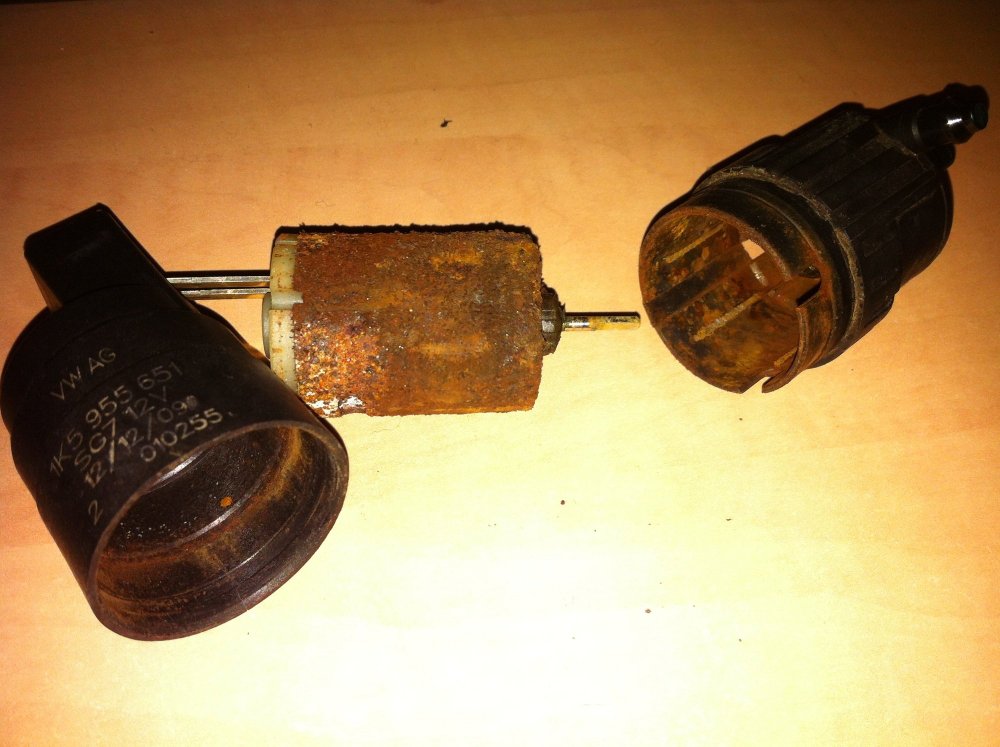
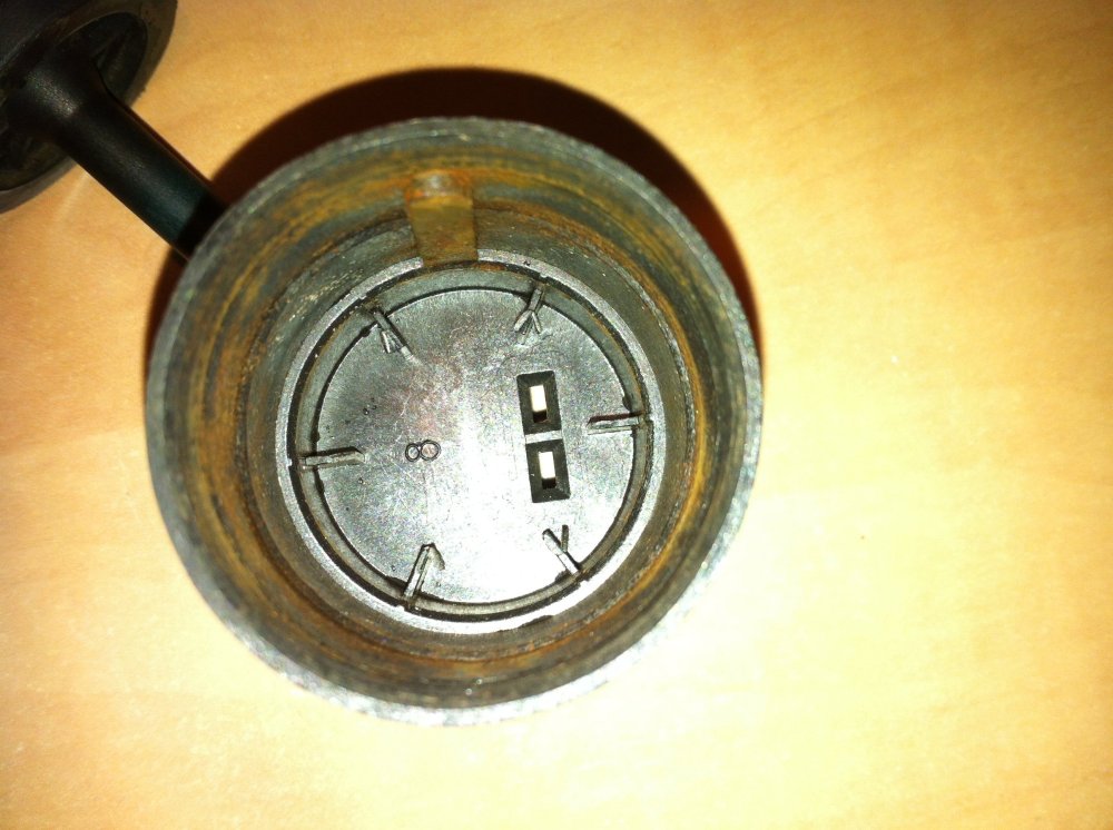
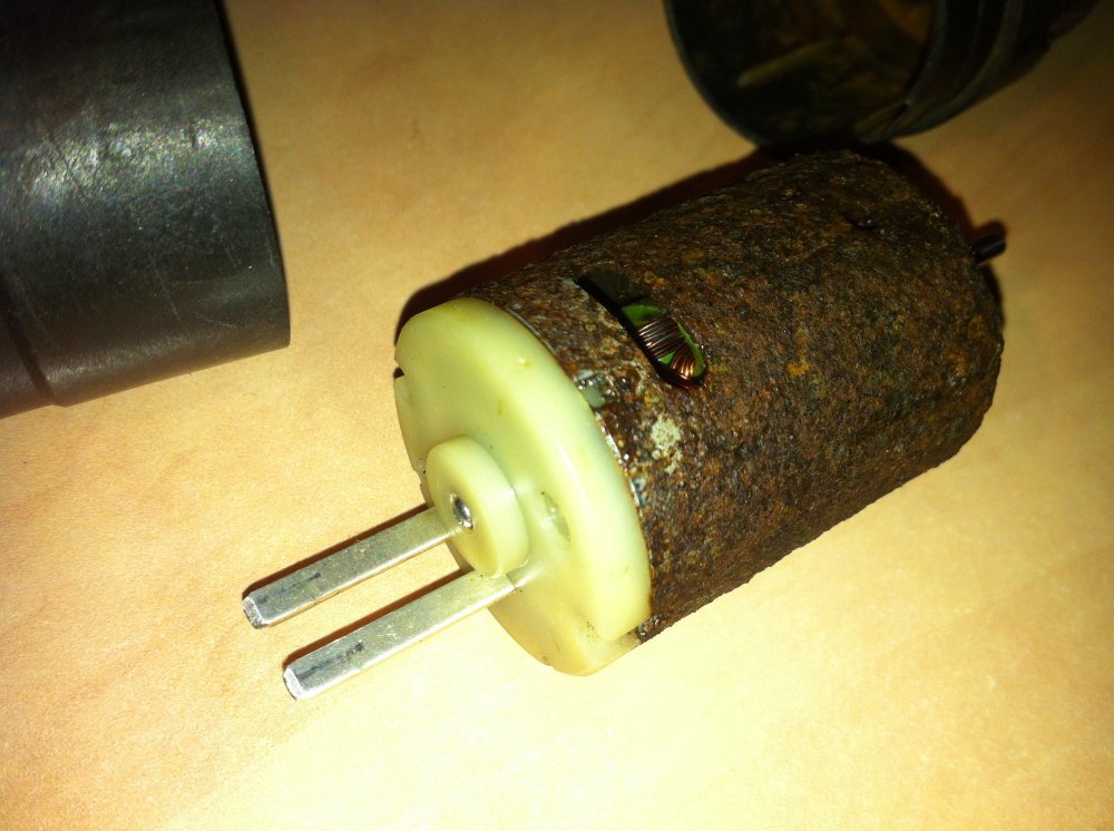
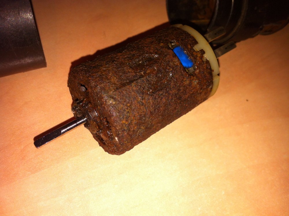
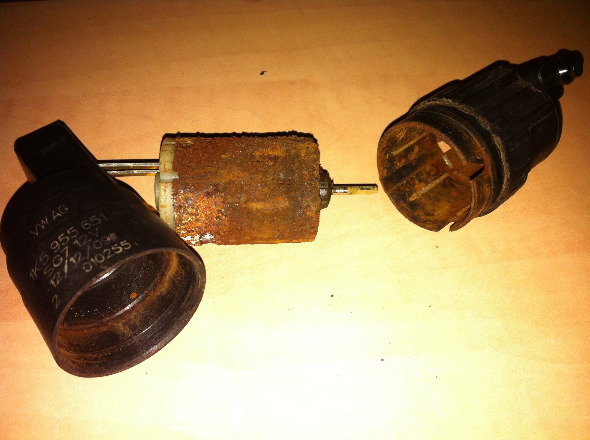
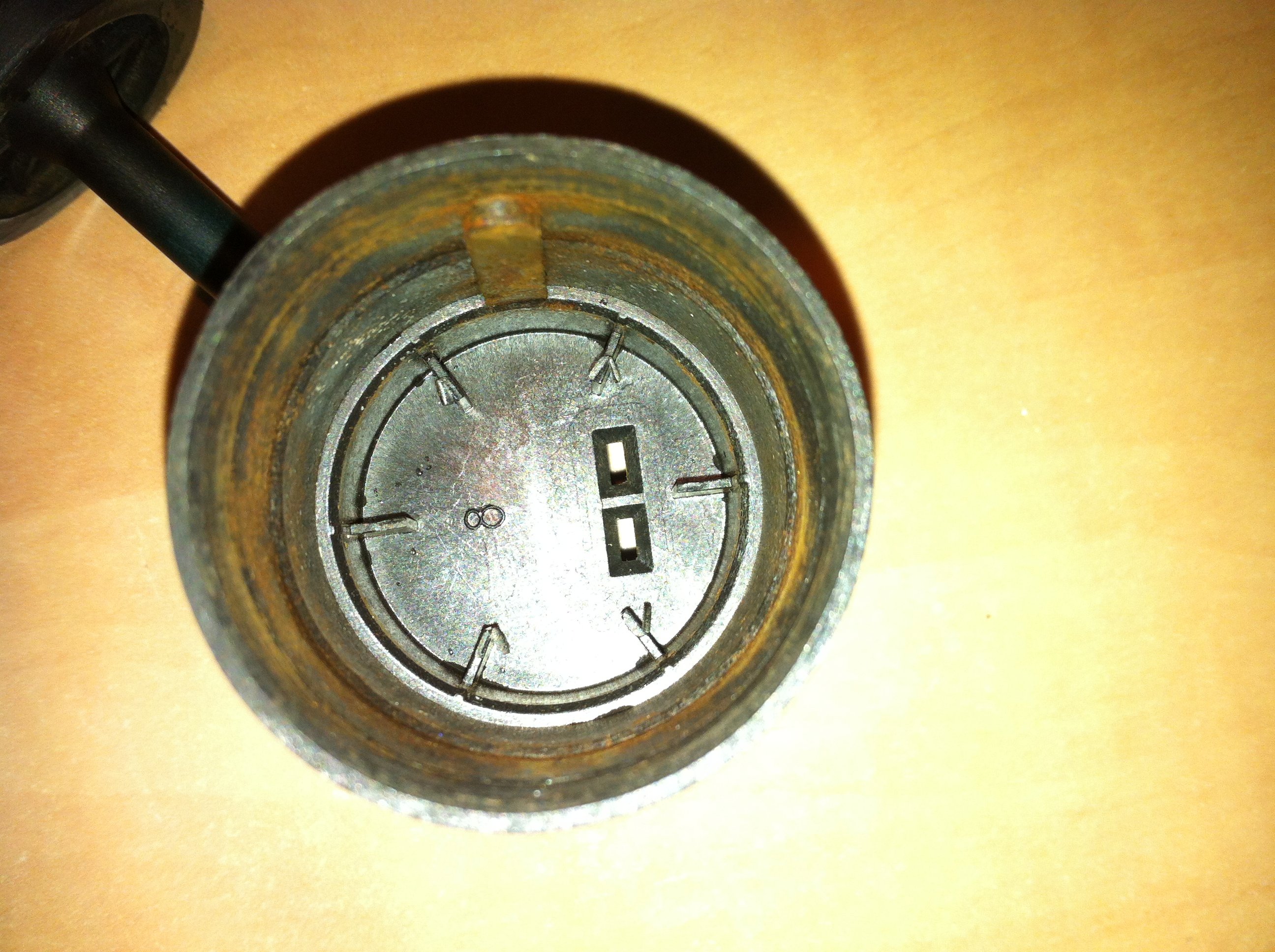
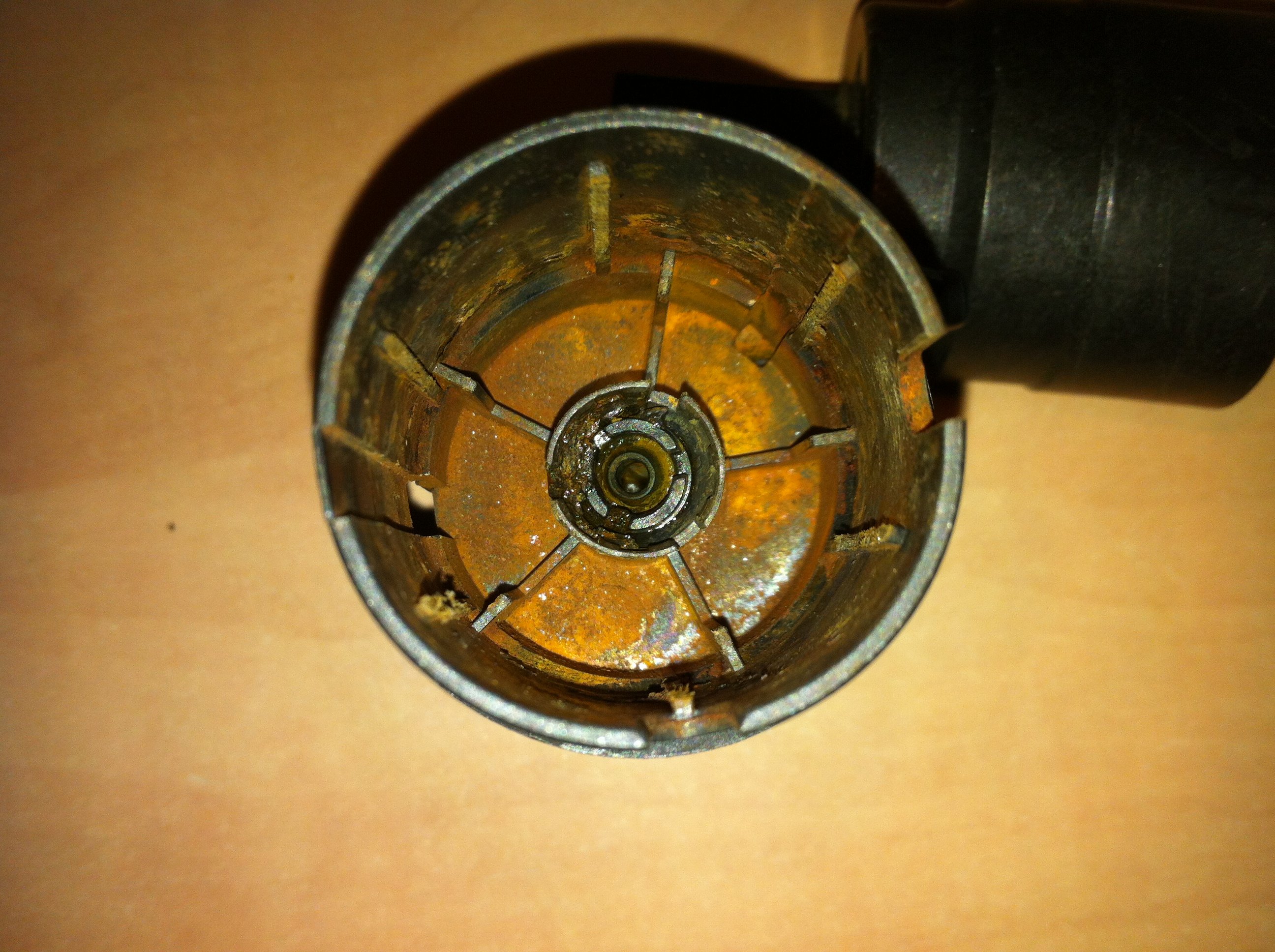
Windshield washer fluid wasn't coming out. A seized washer fluid pump turned out to be the culprit. This is from a Superb MKII but many cars use the same pump. part number 1k5955651 I opened the pump by pulling the two halves apart. Only pulling gets the two halves apart, it can not be twisted. The motor was very rusty and seized, that's why it didn't work. With pliers I got the rotor turning, then powered the motor with a 12V battery inside a glass with distilled water to clean it, worked well, dried it, oiled bearings, I packed silicone grease in the hole that the motor shaft goes into to drive the impeller because maybe from there the water leaked into the motor rusting it, not perfect but at least it is working now. I had already ordered a replacement pump because I didn't believe the old one could be repaired or opened, and only after that I managed to open the pump and repair it, well I will use the old one as it works now and leave the new for spare. The pump I bought was advertised for BMW 67126934159, it was cheaper than a pump with the VW part number but it seems to be the same.


 1 point
 -
1 point
-
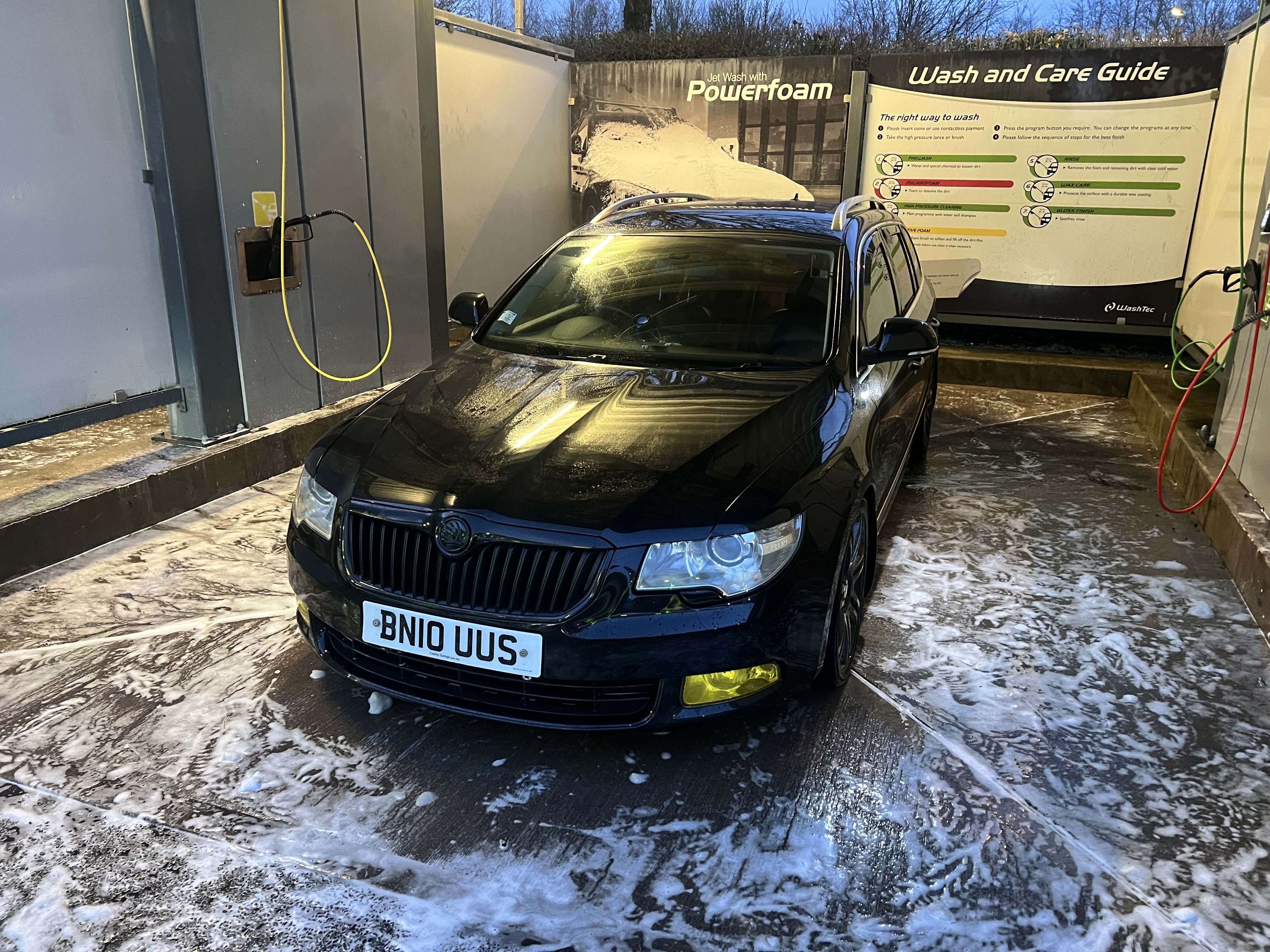
Hello all! It’s been 13 years since my last post on the Fabia forums, and I am now the owner of a 2010 ŠKODA Superb. I have done some mods already, coilovers, headunit, anti-roll bars and some engine stuff, I’ll list that in a moment, my question is, I have a base map loaded into the vehicle to suit the current mods but I am after somewhere that can rolling road the car and give it a more custom map, details of mods below: It currently has a Falcon hybrid turbo (sold as stage 3 - what does that even mean anyway?) a Audi TTRS aluminium intercooler, Darkside Aluminium radiator, 4 BAR Map sensor, Fuel metering valve upgrade (in pump), I have a hardpipe kit and silicone hose kit to fit, Downpipe and an organic clutch fitted. Is there an option for switchable maps? Can anybody advise? Thank you.
 1 point
 -
1 point
-
1 pointHello all. Ok so I've got a 2014 2.0ltr Superb which had a new egr cooler fitted by the dealer back a few months ago under warranty. Since then I've had a vibration which is intermittent. I've had all four injectors tested and they are operating correctly. Though plugging vcds in and the figures for two are out slightly. I was sat idling the other day and the engine went from fairly smooth to rough like a switch had been flicked. Since then I've discovered that if I thrash it, the engine smooths out. Otherwise it's quite rough. I was beginning to think it could be the DMF. Has anyone else experienced this and does anyone know if the EGR could cause this? Thanks.1 point
-
No, not directly related. Earlier versions had a construction fault that was corrected in later versions. I believe this was fixed from 2013. The exhaust points towards the air inlet instead of towards the engine manifold side. So 180 degrees wrong. Many people have fixed this by modifying the connecting pipe adapter into the throttle body. It is a thread about this in the guides section.1 point
-
1 pointMy 2013 Elegance only has the then standard FM/AM radio. Could the problem be related to a faulty heated rear window? I only ask because some while back I had to have my rear window replaced and the "wrong" one went in. I only realised there was a problem because the radio reception was dreadful and intermittent. The screen was replaced with the right one, which apparently had a third contact, and all was well. This time of year with no reason to use the heated rear window you wouldn't be aware if it had developed a fault which might then affect radio reception.1 point
-
Others may suggest that I RTFM but thank you Baxlin. I tried pressing the LH steering wheel rotary knob in and the muting works. A Eureka moment after five years!1 point
-
0 pointsScreen wash is about the only liquid I do buy. No oil for top up or servicing etc. Cabin filter changes at servicing, no air filters or oil filters. Hence why servicing and EV is so cheap as well as its energy top ups etc.0 points


.thumb.jpg.f83a46b9b3c0d976b9dbffbb523c9874.jpg)


.jpg.8ab1d92dabd5f18fdf78059f74541a2d.jpg)