Leaderboard

.thumb.jpg.9dd3f612ba7f13d10be5c518d3c8d255.jpg)


Popular Content
Showing content with the highest reputation on 21/01/26 in Posts
-
3 pointsSounds like the dealer doesn’t give a wotsit, whereas they ought to be on the ball and have it properly sorted before collection. Yes, it is perfectly reasonable to expect matching tyres. They should fix the tracking and pull to one side. An approved used Škoda should have all software updates installed (it’s in the advertising blurb). From your description, the wipers would be an MOT fail so I reckon should have been replaced. D’you feel like ‘naming and shaming’ the dealer on this forum? There’s a section for dealer reviews too.3 points
-
2 pointssounds like complaining enough actually gets you somewhere, they replaced the ****ty Falken tyre they put on it originally to match the new Bridgestone. tracking and the pulling to the left has also been sorted today. software update they are still adamant there is nothing they can do in the dealership and it has to be done OTA from Skoda. My car doesn't have the OTA capability according to this website Availability List It's Ingram Skoda in Ayr. Sales seem to be a complete joke in all honesty, but now that it's been in the hands of the service department it seems to be actually going somewhere (except the updates)2 points
-
2 pointsPretty sure that the fluid is not tested for MOT, and the brake efficiency test that is actually part of the MOT would almost certainly NOT show up high moisture content in the braking system - that WILL show up in braking while descending a long slope - or a hard stop from high speed!2 points
-
2 points
-
2 pointsDoes the car have a full service history? I agree with Warrior193. Something other than ACT is at the root of the problem.2 points
-
2 pointsAll the above written is correct, except 'Ferodo' and not 'FeRRodo" but we forgive him because he has left us ... 😁 I have never seen "long life" brake/clutch fluid ... don't trust that. Some brands come in 500ml containers, also useful, considering the limited shelf-life of the product once opened ...2 points
-
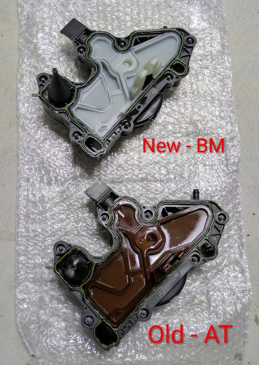
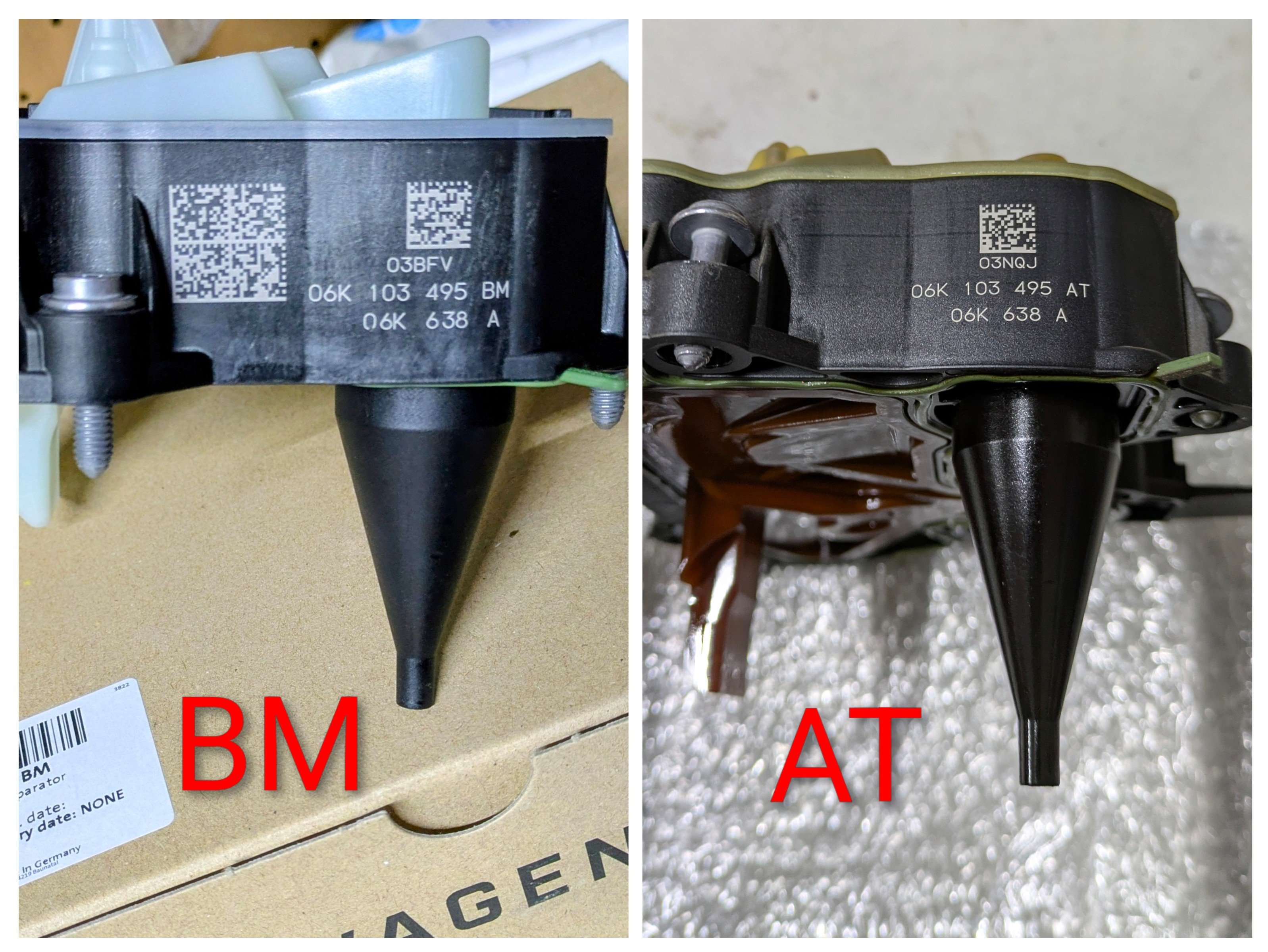
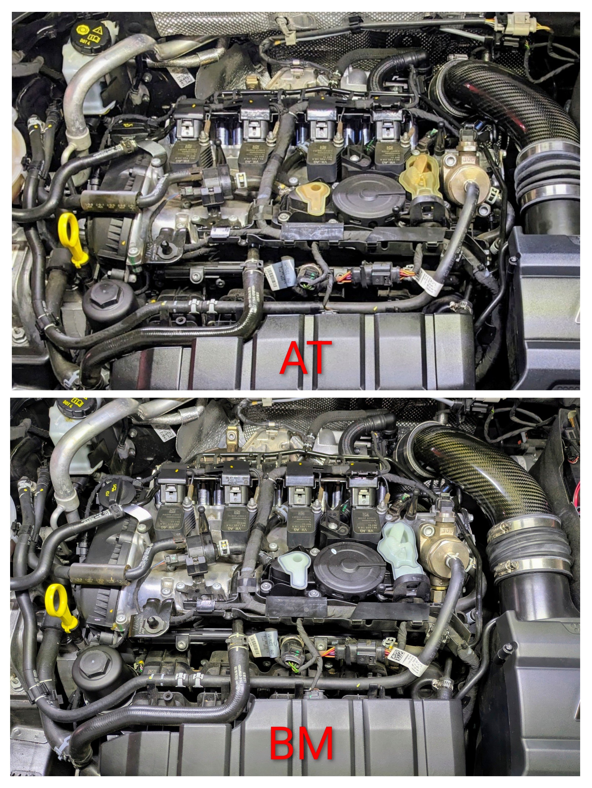
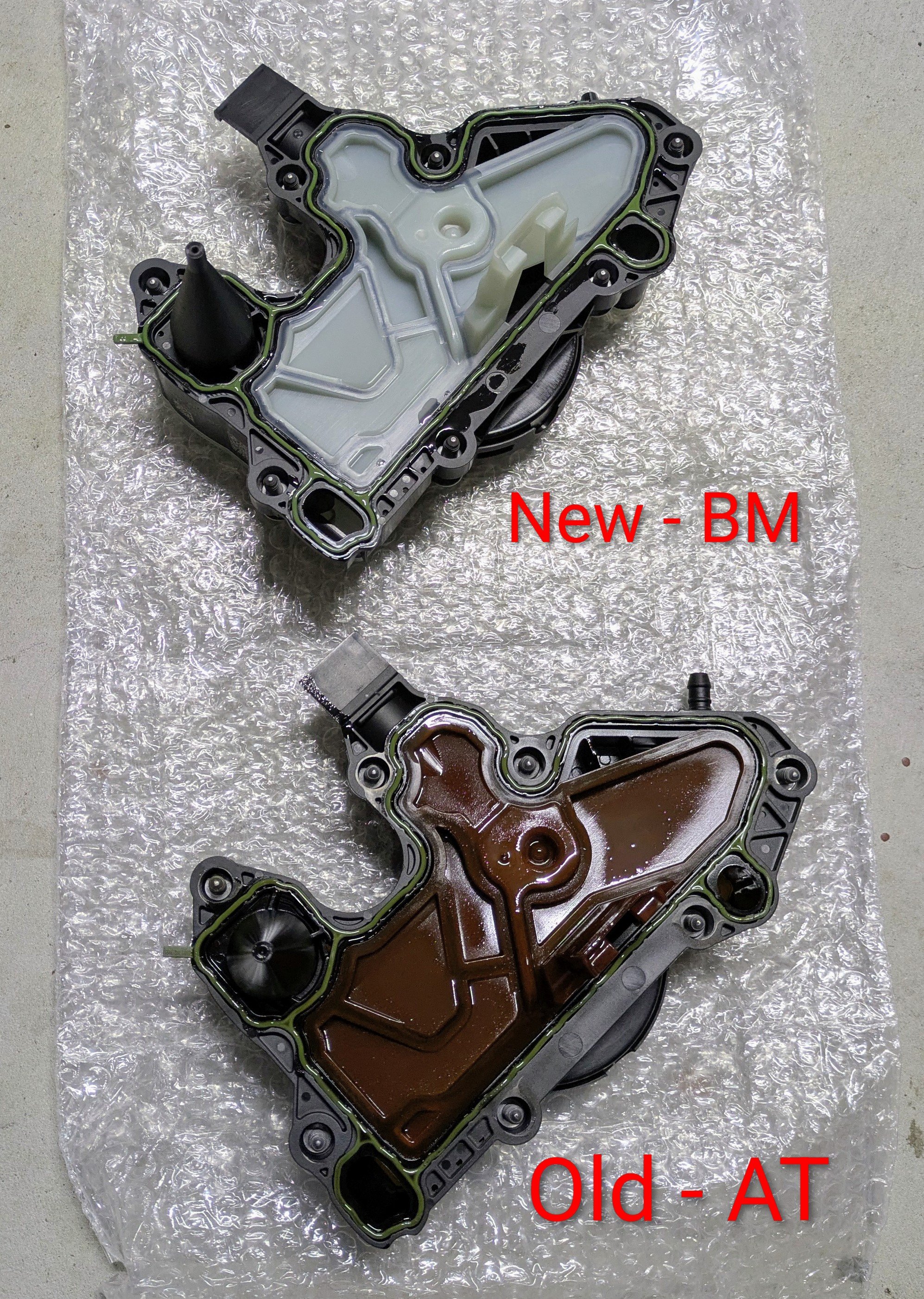
2 pointsThanks to some wise words from a smart friend, I changed Gandalf's PCV valve. There wasn't any issues with Gandalf, rather I replaced the PCV valve was as a preventative measure given Gandalf is 8 plus yrs old, and the various modifications over the years. I've heard the old AT version has been known to fail. As with new refreshed parts, car feels a bit more smoother under load/boost now. I previously thought it was a quirk of the Galano ECU/TCU tune, but the change of the PCV valve seems to have smoothed this out. Most likely placebo, but this a new and better revision of the PCV valve. Less problematic based on my research recently and the few techs I've spoken to. Old:- 06K 1034 95 AT New:- 06K 103 495 BM Removing the old and replacing with the new was fairly straightforward. Hardest part for me was removing the original crimp band clamp, holding the rubber hose to the PCV valve. When fitting the new, I replaced it with an OE spring band clamp - N90686701.


 2 points
 -
2 points
-
To close this post , as the problem was finally sorted, by moving the boot lid catch on the door frame about a quarter of an inch beyond the normal adjustment. ( rearwards towards the back of the car ) Everything works perfectly now.....happy days......especially as we seems to be having non stop rain here in the West Country so wipers , front and rear, are working overtime. Thanks to everyone who offered help and advice.2 points
-
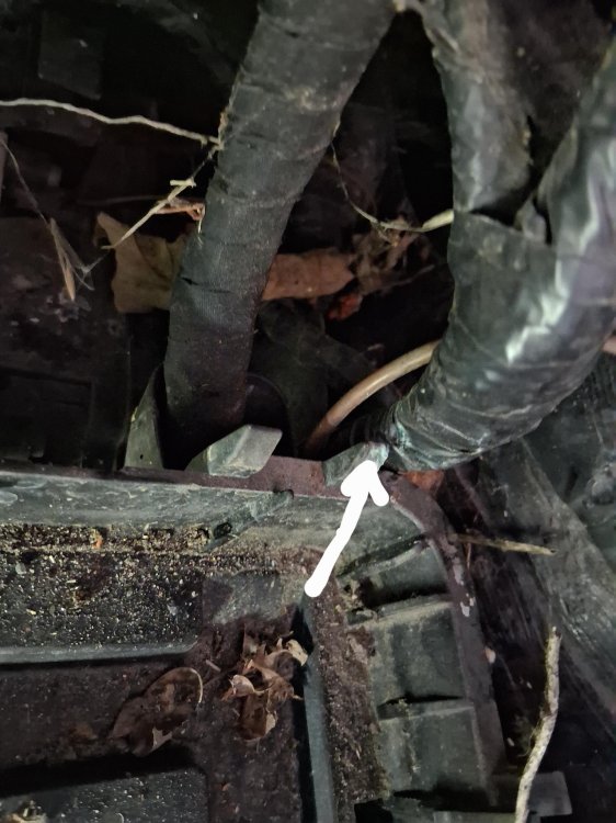
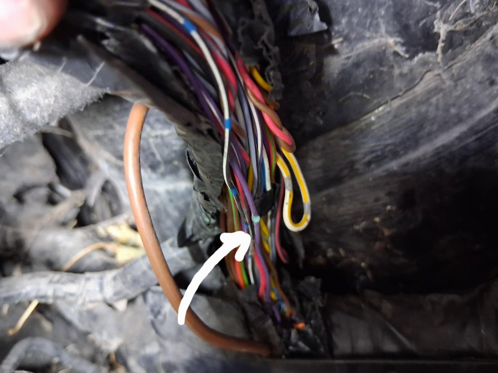
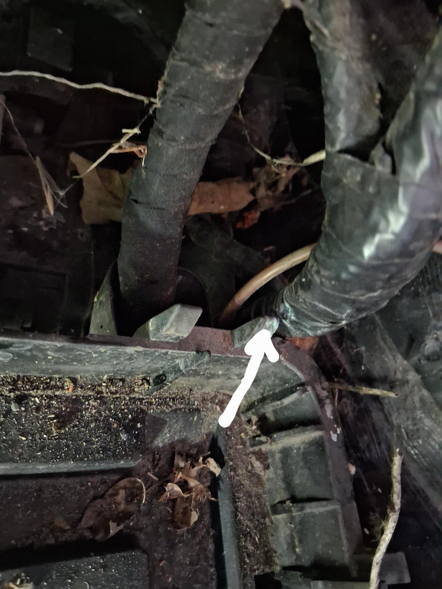
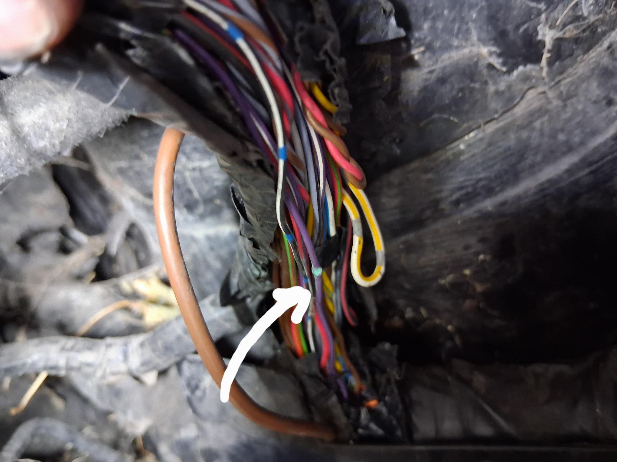
Hi everyone, I own a 2012 superb diesel 2.0L, and the front wipers have been working intermittently for the past few weeks. I wanted to reach out to anybody that has also encountered these symptoms. Before I get on to how I repaired it, I have tried cleaning the contacts behind the wiper switch/stalk, still not working. I replaced the wiper motor J400 type and still not working. I replaced the BCM with the same part number, still not working. Just to note all of these parts were second hand from a salvage yard. The only function working was the windscreen washer jets, not the headlights. I looked through a good few forums on BRISKODA, and to be fair all of the suggestions were good ones to try rectify the wiper issue. If anybody is trying to clean the contacts on the wiper stalk, be careful putting the arm back into place as I broke off a small plastic lug, that operates the pull back washer function. This cannot be repaired easily, and it's not worth the effort as it's tiny. This is why I replaced the full stalk unit(second hand), as a main dealer part is expensive!! So onto the fix... 3 wires coming out of the motor. Live Earth LIN( purple) With multimeter I was reading system voltage on the live connector 12v I connected this wire directly to positive on the battery and got 0v.. so no voltage drop. I did the same with the negative cable on the motor. With multimeter I was reading system voltage when connected to battery positive lead 12v I checked this connector for voltage drop by connecting it directly to battery negative and got 0v The LIN bus (purple) cable was reading system voltage also when using a multimeter to earth of the battery. I read a forum that stated a customer has brought his car to an auto electrician and they found an issue with the wiring loom between the bulkhead and the battery box holder. I removed the wipers, wiper cowl, both sides, I removed the wiper motor, I removed the ECU which is located to the right of the motor. I removed the ECU holder(plastic). I removed the battery. I followed the wiper motor wiring loom and it goes through the bulkhead and down below the inner side of the battery box plastic holder. On closer inspection I spotted the loom was tight against the edge of the holder, and could clearly see green oxidation. I removed the battery box holder and stripped down the insulation around the loom, and found the purple cable was squashed and green with oxidation. This was the cause of my intermittent wiper operation. The high resistance within the cable was causing the issue. I found that the wipers worked at random in the very cold weather, maybe because materials expand and contract in cold weather? I have attached a few pictures to show where the issue was. I found an old breakout box wiring loom from over 20 years ago that had wires the perfect size and color. I just cut out the damage bit, about 4mm of cable and added in new. I used head shrink, but allowed an inch extra long on the cable. I taped up the loom again and used 3/4" qualplex pipe insulation to put between the loom and the battery box holder. I actually grinded off a little bit from the corner of the battery box holder. I put the car back together and it works perfectly, even the headlamp washer jet works again!! I hope this long winded explanation helps somebody. Just to note I didn't have any diagnostic tools, however I've over 26 years experience as a motor mechanic!! I'd say if the system was checked, I'd say it would have read high resistance or open circuit for LIN bus cable, between J400 and the BCM under the driver's side above the clutch and brake pedals.
 1 point
 -
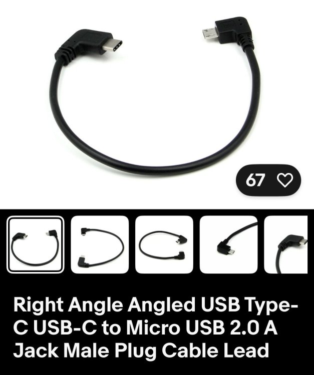
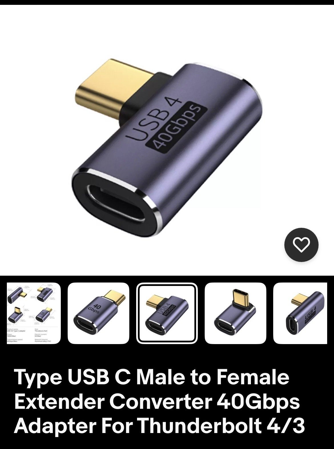
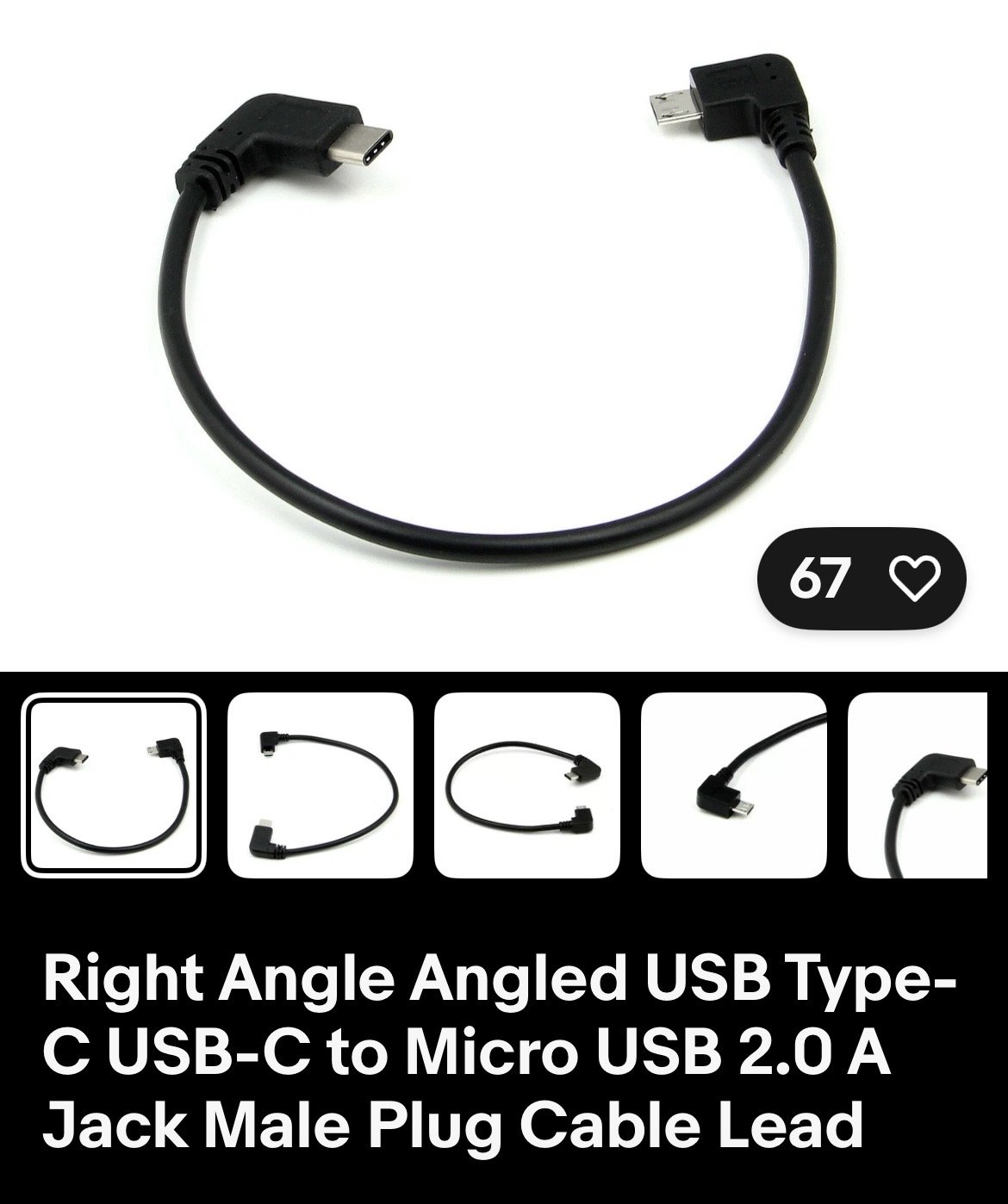
1 pointYes usb-c socket by the rear view mirror. Fitted a Nextbase in my Octy just need to buy a shorter power cable Bought these for a neat fit on EBay

 1 point
 -
1 point
-
1 pointI had a similar issue on my Superb 2 litre diesel with 190hp recently. I was initially thinking it could be the dual mass fly wheel, DSG clutch pack or even the DSG related. I was talking to a local indy who suggested it might be the crank position sensor going faulty. Had them change it and car has been good since.1 point
-
1 pointCan't do the back end of the week unfortunately as I have prior commitments, but I appreciate your offer and may well be in touch soon to act upon it 👍🏻1 point
-
1 pointTypical, we're miles from everywhere 😅 Quite busy next week but we may be able to get you in on Friday/Saturday 🤞🤞1 point
-
1 point
-
1 point
-
Some of the VAG engines are actually designed by Skoda (the 3 cylinder ones IIRC), and all of the VAG software (whether it's used on VW, Audi, Skoda, SEAT, etc.) is outsourced to third parties. The only difference is how much time and money each 'brand' spends on getting the software problems fixed.1 point
-
1 pointIt didn't lie it just doesn't know what it's typing about. You always need to double-check and cross reference any information you get from any source but possibly much more with AI chat things. Not necessarily they have used a different weight range of oil 5w-40 instead of 5w-30 that is not the end of the world. A 5w-** oil will be good oil as that's what required to meet the 5w (winter cranking, starting of the engine) the 30 or 40 is more about when the engine and oil are warm/hot. The 40 of 5w-40 may be close to a 30 in a 5w-30 as the 30 and 40 numbers relate to a range within the actual number especially as things change with the use of the oil in the engine. Also bear in mind your location where it might get very hot weather where the garage might prefer the high number oil. You could check that the oil they used matches the VW spec number 5** ** your particular engine requires. You need to ask the garage, it could be a typing error on your bill/invoice or they prefer the use of 5w-40 in your location, or perhaps they just have 5w-40 oil to get rid of. As long as the 5w-40 oil is suitable for your engine, in your location with your use of the engine it could well be fine and better than a 5w-30 oil of a lesser quality and suitability for your engine use.1 point
-
1 pointIf only seen when first starting and then it goes away there is a chance it is the first sign of a 12v battery voltage drop. I would wait until it gives you more info either with another lamp or message in the system messages. Could also be a dodgy earth connection to the body from the battery, once the car is run the problem goes away.1 point
-
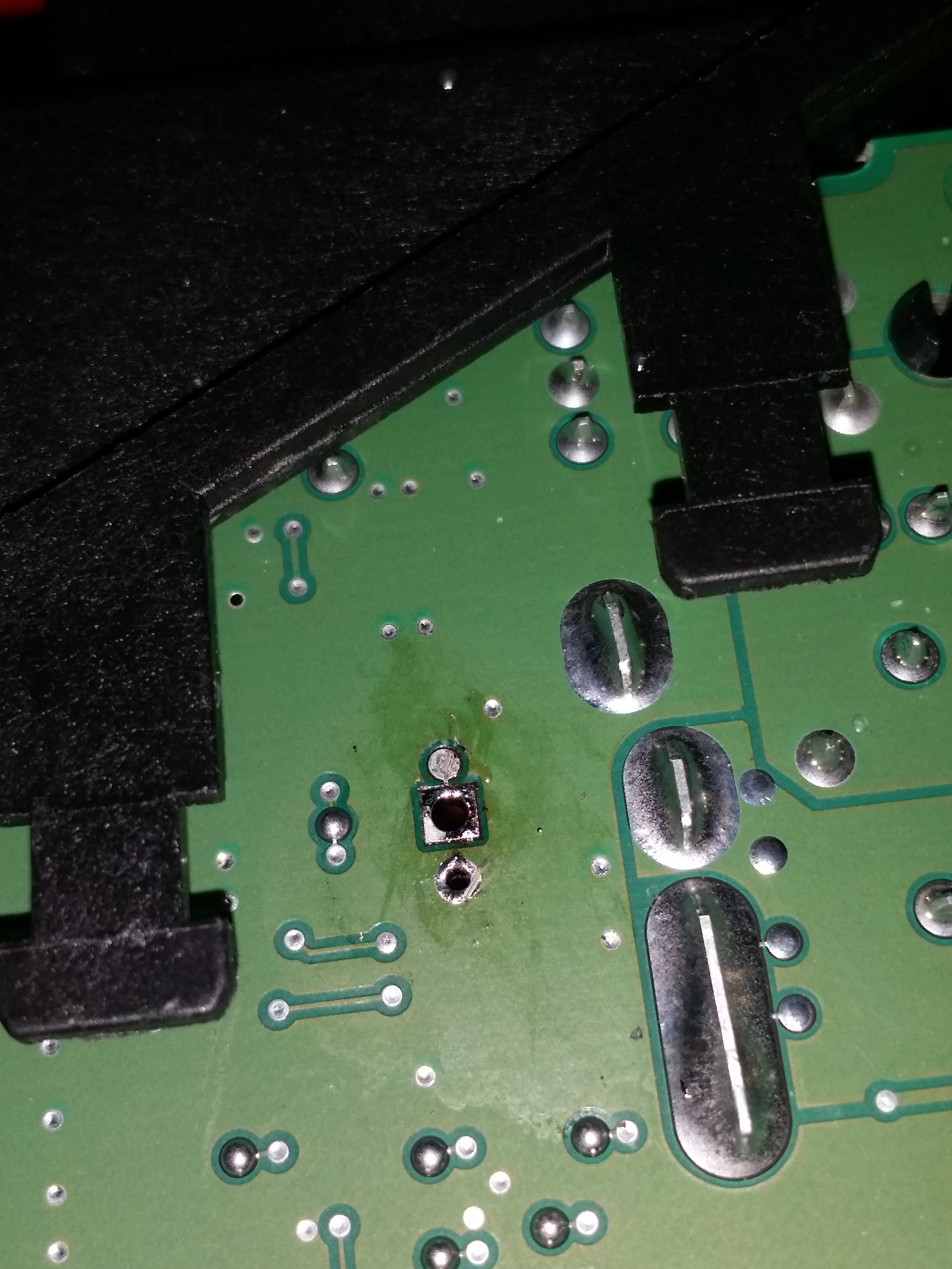
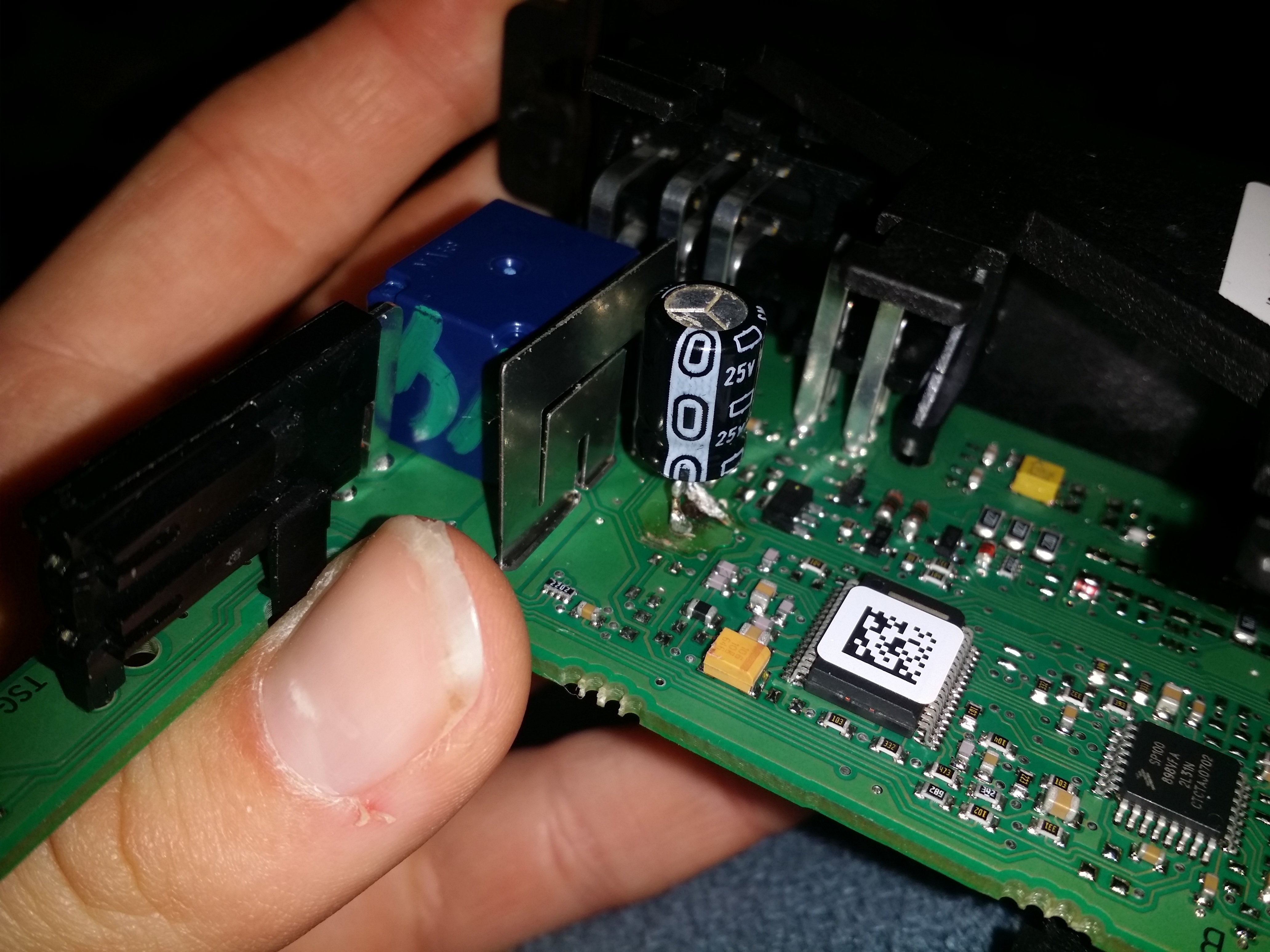
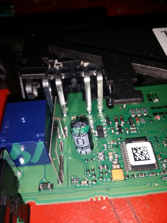
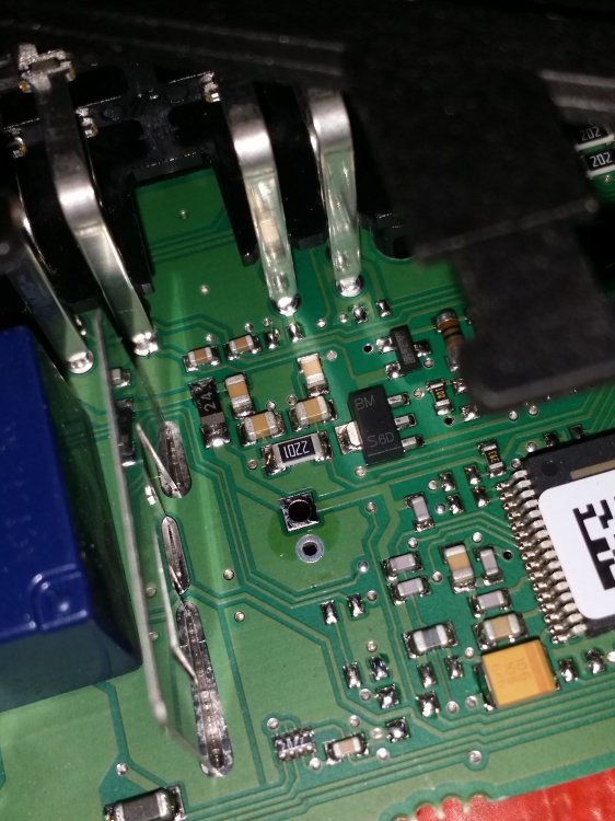
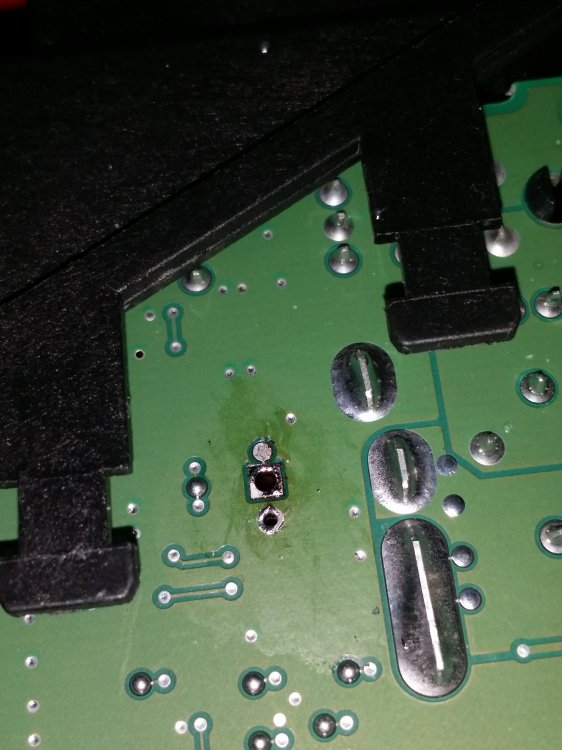
Good afternoon all who spend their weekends fighting Mk1 Fabias' quests to join the scrapheap. As this information does not seem to be clearly available on the internet (only scattered hints) I thought I would write it down and share it. As I'm sure many of you know, the facelift MK1 Fabias and I believe also the pre facelift Mk2s (and 9N Polos, early Roomsters and T5s must have the same problems if they have the same modules) have electric window drive modules that get to a certain age, then only work intermittently. Typically, they work when the battery has first been connected, and then stop working about 5 minutes later. If you reseat the fuses it seems to reset them and then they may or may not work again for another few minutes. When this happens, you then go on a wild goose chase, starting off thinking it is a battery voltage problem, then maybe a switch problem, then maybe a wiring problem in the door, or maybe even a comfort control module problem (gasp!). You also think maybe the module has failed and look on the internet and see whatever extortionate price is currently being charged for a probably also faulty second hand replacement. For reference, my car is a facelift mk1 Fabia, registered in March 2007. The window modules have mfg dates in February 2007. I am 99% certain the cause of this is faulty capacitors in the electric window modules - 1% uncertainty in case there has been a freak accident I am unaware of causing mine to work again. To open a module, there are no screws, you just need to find some thin tools to use as wedges. I used a screwdriver or plastic trim tool to lift each clip and then an ice lolly stick I cut down to keep them wedged open while I did the next one. When all clips are wedged open you pull the two halves apart. One side contains the motor and power contacts for it, the other the electronics that read the switches, communicate with the other modules, and drive the motor. You can remove some more of the plastic around the connector sockets but it is a bit fiddly. The electronics side is where the problem is. Next to a big plate shunt resistor thing, there is a single electrolytic capacitor, that probably has green stuff on top where it has failed and vented. The negative side faces he nearer edge of the board, away from the switch connectors. This is probably the only component other than the relay that is feasible to replace if it goes wrong, those being the only two components that are actually labelled with what their values are supposed to be, and the only ones big enough not to need micro soldering equipment and skill. Being an electrolytic cap this is probably the only one liable to fail with age, thankfully. The original cap is a 35V 100 microfarad part, specifically the epcos B41851 (which I think I found you can still buy), though any 100 uF cap with more than 35V tolerance should work fine as a replacement - I used some 50V ones I found fairly cheap. To cut a long story short, I have two modules now in my car (rear are manual in mine thankfully) that work reliably and fully after replacing that capacitor in each. I do not believe the relay needs replacing, as a module just works until it doesn't, then starts again when power is reset, rather than half working all the time in the way you'd expect with a faulty relay. The relay is also an off the shelf part that can be replaced if it is faulty, but it is unlikely that it will be. I will say that it isn't the easiest soldering job in the world, as it seems to require a fairly high power soldering iron to properly melt whatever solder they used. It probably also doesn't help that the cap is connected to the relatively large shunt resistor (the funny shaped metal plate) that soaks up a lot of the heat. I was trying initially with a 25W iron, then later a 40W iron, but I think if you want success, don't repeat my failures and instead use something better like a 60W or higher. It would also probably help not to use a solder sucker with a crack in the nozzle as well. I am aware that Breezy Pete offers a repair service for these modules, and the knowledge that he gets them working by repairing the module was a very useful clue. I thought that this information would be helpful to be out there on the internet regardless for people who like to do board work themselves, and people in other countries. But if you do not like to interfere with electronic components like these modules, or you don't have decent soldering equipment and you don't want to get into it and invest in some, then that repair service is probably still your best option given it can be a bit fiddly and frustrating, and dangerous for the board if you are not well enough equipped. I wanted to try and demystify this though after spending whole days investigating this and enduring the amount of frustration I have over what should be a simple thing. I am not completely sure how the failed capacitor causes this kind of failure. The modules are clearly capable of functioning with a bad capacitor as they do that when they are reset. I seem to remember someone on here measuring wire voltages and finding that some other part of the car cuts power to the module after a few minutes. Perhaps a comfort control module or something like that lets them run for a while, then sees that the module has too high idle power consumption due to the capacitors leaking current, or senses that it is a hazard in some other way, and then cuts power until they are reconnected? I did however manage to make my case into a long story, by initially using old salvaged capacitors I had to hand instead of buying new ones, so that the modules worked only for a day until we replaced them again (my dad did it later on as he is better at soldering). One also detached due to a particularly bad soldering job I did (they are through hole, but I ended up soldering to the old leads as I had a lot of trouble removing the old ones with my poor equipment and skills, and on one directly to lifted traces). At some point during trying to resolder one, I must have damaged something else on the board, because that one doesn't seem to work any more even with the capacitor having good continuity to the other components attached to those pads. So I think my poor soldering skills and persistence with them may have destroyed a module which is really not good. However, we had a backup. My uncle is a car trader and happened to have an 07 Polo he was scrapping. He kindly took the modules off for us, though he didn't think to check if they worked beforehand, assuming they did. This is where it gets confusing. Before any of the cap business, we had tried these Polo modules on the car and found it did not fix the problem. However, I can't remember if it had the same behaviour as before or just didn't work at all. After the cap business, we had to try one of these modules after I presumably broke one of the skoda ones. We replaced the caps and tried the Polo modules, and combinations of Polo and Skoda modules. They did not work properly. After a lot of head scratching and wanting to smash the whole car up with a hammer, one of us realised that we were trying the polo driver side module on the passenger side, and the polo passenger module on the driver side. This happened because the modules are physically the same, but flipped on the Polo vs the Fabia (I suppose someone clever at VAG was asked by their boss to figure out how to create the most possible confusion for DIYers for the least possible investment in new parts) causing each module to only mechanically fit on the opposite side to which it is supposed to run. You'd think this wouldn't make a difference to anything, given the hardware and software numbers written on the electronic parts are all the same on the Fabia and Polo modules on both sides. But there must be some kind of software coding that is aware of what side's window switches it is connected to, because you can have two modules on the wrong sides be completely dead, then connect them on the right sides and they work flawlessly. The solution to this, as the motor part of the modules are the same for each side apart from the output shafts being on opposite sides, is just to remove the electronic parts from the motor parts of the modules using the method detailed earlier, then swap them. After this they work perfectly, even if one side says Skoda and the other VW. Each module is labelled "PDRS" for passenger side, "DDRS" for driver side in the part code. The Polo was a right hand drive UK car as well in case that makes a difference to anything. The Polo modules were made in March and April 2007. I discovered some other window module quirks along the way that can be confusing. If you only have one working module connected at a time, even if it is not faulty, it will not function properly without the other, even if it is the driver module. If i have only the driver module connected, it will work on its own, but the one shot winding will not work, and the window will work even if the keys are not in the ignition and the car is locked. Apparently it gets power for that somehow. As soon as you connect a working passenger module, it immediately snaps back to the proper behaviour, where it works only for a brief period after removing the keys and not when the car is locked. Then when you turn on the ignition again, both modules work and the one shot works too. When you have a working module connected to a non working module, I can't remember if it doesn't work at all or has the same behaviour as one working module connected. I think the passenger module on its own behaved similarly to the driver side on its own. In the end I got it all working, until two weeks ago when I accidentally tried the one shot on the passenger window while it was iced up, and I couldn't stop it before it screwed up the regulator. A job for later in the year I guess. Here is a photo of the original cap of one module: Here is the board on both sides with it removed: Here is my dodgy replacement after I realised the first cap I put in was already bad because I didn't think and then replaced it with a 25V that seemed to be good but only lasted about a day. You can see my poor soldering technique and use of low power soldering iron has led to pads and traces being lifted when previous caps were removed. On the far left of this photo you can see the terminals that insert into the motor half of the module to provide power to it. Behind the capacitor you can see terminals for the switch and (presumably) central control connectors.
 1 point
 -
1 pointFrom your pevious replies I would hesitate to call you naive. I don't believe for a second this is a feature (it would be the most pointless ever). This is clearly a defect. Whether it affects only a limited number of vehicles is not to the pont, it is still a defect which Skoda has been advised of. In true 21st century corporate behaviour it will not publicly admit to the defect but will fob cutomers off with any old excuse under the sun until the real technicians do some proper testing and remedy the fault, or until a significant number of car owners begin to reject their cars under Consumer Protection legislation and tell the general public through social media of the reasons why.1 point
-
1 pointMine from the above has just cleared customs, should arrive tomorrow I am hoping and then can get this installed. The true Skoda retrofit is very involved with Skoda quoting £500 then fitting also looking at nearly £1000 be the time it would be done.1 point
-
1 pointDiagnostics brought up no misfires Changed spark plugs 2 weeks ago and coil pack a coupke of months ago No difference at all I change oil and filters regularly1 point
-
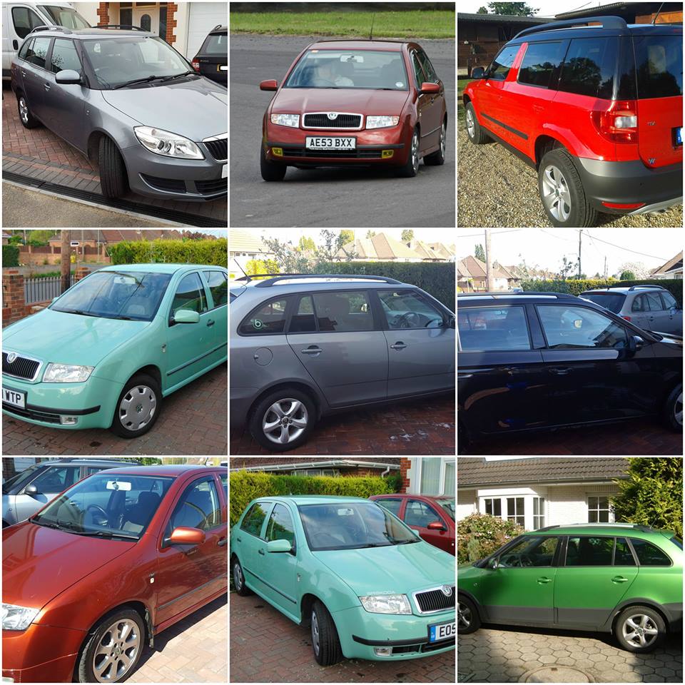
6U0885695 H50 (pre-facelift - darker colour) 6U0885695 5SE (facelift) Try searching just the first 9 characters. The last 3 are colour variant.1 point
-
1 pointWith the greatest of respect I think you place too much faith in Skoda Dealerships and in users manuals (which in many respects are no real use). I'm convinced PHEV and pure electric Skodas have been rushed to market, without adequate systems testing, just to show the world that Skoda are ahead of the Zero emissions mandate.1 point
-
1 point
-
1 pointIf I can give some advice: go polyurethane. It completely changes the car’s feedback for the better—more stiffness and better cornering capabilities. You might also consider adding a rear sway bar. My Fabia combi (not a vrs just a 1.2 tsi stg.1 revo) is fully on 90 Shore polyurethane bushings from Strongflex (yellow bushings), Koni Sport (yellow), and various Ultra Racing braces, along with Whiteline front and rear sway bars. The car feels glued to the ground, (especially in summer with the Yokohama AD08RS).1 point
-
Sorry to bring it to you, but VW and Skoda are pretty much the same cars, sharing all the same problems. VW is a bit faster to roll out SW updates, but until all is updated, issues are the same. Also, Skoda is not cheap anymore.1 point
-
1 pointI usually buy two as well especially if the old ones have been on car for a while. Have had a couple of cars that didnt quite sit level due to one spring replacement as older one I assume being weaker/different make. I generally change any suspension/steering items in pairs especially front. Alasdair1 point
-
Thank you for the link and guidance. The story was very helpful from the beginning till the end (not just the post from 21 Jun). I should remove the intake and clean it as well. You did a great job ! Congrats!1 point
-
1 point
-
1 pointit is not very easy for a DIY mechanic, at least for me, at this time of year and without an elevator, I would not do it.1 point
-
It never stopped 😭 As others stated, many bugs are fixed, but it just continue on. I have never seen a mainstream car with so many bugs. It's been 6 months since I bought my car, I already start to feel that I already had enough. The equation is quite simple: if you buy something cheap, what you going to get this quite cheap too. If you are a type of person who gets annoyed by stupid mistakes made by the manufacturer, are you advise you to go and buy a Volkswagen and don't waste your time and energy on a product made by a couple of short-sighted engineers.1 point
-
Resolved. Working with both Apple car play and AA. Just came down to the usb cable for android. Although it worked with a laptop for data transfer probably too long for AA.1 point
-
1 point
-
1 point
-
It is apparently now sorted! It's worked fine so far, but only had to start it warm once... 🤞 Apparently the issue was the timing on the diesel pump, and they've not charged me anything, despite it taking 5 hours or something to strip down and retime. As long as it now behaves, I'm reasonably happy! Not sure I'd go to the same garage again for a belt change though... Thanks for the help 👍1 point
-
1 pointI will check it. In the meantime, I also read elsewhere that second gear is harder to engage in cold weather. Often it works better if I shift from first into neutral and then into second. I mean that others have complained about this as well.1 point
-
1 pointWonder if you have an airlock somewhere after changing the stat. Some require vcds or a vaccum fill to bleed properly. Not sure on your CBZB engine. Try and squeeze top rad hose again and again and look for bubbles in coolant tank or see if it drops. Do the heaters work in car? Alasdair1 point
-
1 pointDOT4 is the required references in VAG workshop manuals. You can find DOT4 in any autostore, some wear specific mention "ABS and ESC compliant". Regarding brands, I've used Valeo, Febi, Ferrodo and Brembo several times without problem. As I do it myself, I rather buy 1.5 liter, just to be sure I have enough fluid to do one of the four calipers twice, if needed... And this costs less than €20. Having it done by a local mechanic is around €80.1 point
-
1 pointI am not surprised ... I am lil above 5-0 and dealing with cars half of those years, and sometimes I still embattle with "people in the trade" who sustain things like "coolant is for life" and such ... oh well. So it is ... Unfortunately you will not find this in the owner's manual, as it is "left to the dealer". For fluid, any good DOT4 will do (I favor ATE or Febi, in any case renown products). Capacity should be ... with one liter you will have more than enough, I seem to remember overall fill from empty was 1-1.15lt, but there is alway some left. You need diagnostic system to open/close the ABS pump though, so maybe some assistance will be needed.1 point
-
1 pointI managed to resolve this myself on my 2020 Skoda Karoq. I appreciate that this post is a couple of years ago, but I did some extensive research to try and find a solution, so I thought I'd share my answer. Apparently, when the backup OCU battery health is crap, the SOS system comes up with an error, which doesn't affect your driving but knocks the signal out for your satnav, interferes with the microphone on calls, and has a very irritating warning light. Mine reset when I left the car off for a while, or held the SOS button for 20 seconds and made an emergency call, and cancelled it again, but it always came back. I found this was a possible issue and found the OCU backup battery here: Volkswagen / Audi / Skoda Battery For Emergency Supply 3G0915089A - LLLParts I called a local dealer to confirm it was the right fit for my model, and it was, then just bought it from that site as it was about £45 cheaper than the dealer. Then you have to take out the unit, which for me was behind the headlights control. I removed the panel under the steering wheel with a hex screwdriver, and used a 10mm socket wrench to take off the Gateway Unit (part number, which I could see when I took the panel off was 3Q0 907 530 AG). Then the OCU was stacked on top of that (part number 5WA 035 284 B). Swapped the battery in the OCU with the one I bought, popped everything back in, and never had the issue come up again. Notes! There is a recall on certain Skodas I found out for this issue, sadly mine was not one of them, it's worth calling and checking if your car is part of this, as a software update can sometimes fix it if this is the case. Remove the negative terminal on your battery before doing any of this, so you don't blow any fuses or get a bit of a shock!1 point
-
1 pointI would rather think about ripping CDs to audio files (e.g. mp3) and put them on SD.1 point
-
Solved ...Polen filter sliding cap loose1 point
-
1 pointLeave the power on for about half an hour and it should go back to the entry screen. The procedure for entering the code is a bit odd, I can't remember what it is but it's in the owner's manual. I've used these for a few codes in the past and never had a problem https://www.onlineradiocodes.co.uk/1 point
-
1 point
-
1 pointCheck that the seal from the previous oil filter isn't still in the housing, this has happened to me before, see https://www.briskoda.net/forums/topic/532356-timing-chain-or-throttle-valve/#comment-59427601 point
-
1 pointHi, Not very common where I live, I then took the opportunity of a quick picture this morning:1 point
-
As @ApertureS indicated above - yes it crucial u get the correct version - i.e. RHD in ur case. 3Vx 941 01y A - x=LHD(1) / RHD(2) y=left(5) / right(6)1 point


.thumb.jpg.f83a46b9b3c0d976b9dbffbb523c9874.jpg)