Leaderboard
-
MikeTheThinker
FREEDOM19Points8,484Posts -
.jpg.1006585dfe4e2977315b67c3d642e37b.jpg)
Guest_
FREEDOM11Points83,824Posts -
varooom
Resident Member9Points4,411Posts -
TheUltraRunner
Members7Points1,258Posts


Popular Content
Showing content with the highest reputation on 25/07/22 in all areas
-
7 points
-
3 pointsOut in the wild! After 100km or so of general driving the fuel gauge seems to have settled to a consistent reading, about 10l less than the actual amount but as long as it stays consistent that's fine by me.3 points
-
2 pointsIt's very simple, the PAS pump uses a massive amount of current, around 60A peak, if the alternator or the battery are not in tip-top condition then the reference voltage will quickly sag under this load and the ECU will shut down the PAS pump to try and keep the engine running properly. I don't care how you fix it, just stop going around in tiny silly circles. Once you have the battery and charging system working perfectly then the next stop is a secondhand pump and that should be the end of any problems.2 points
-
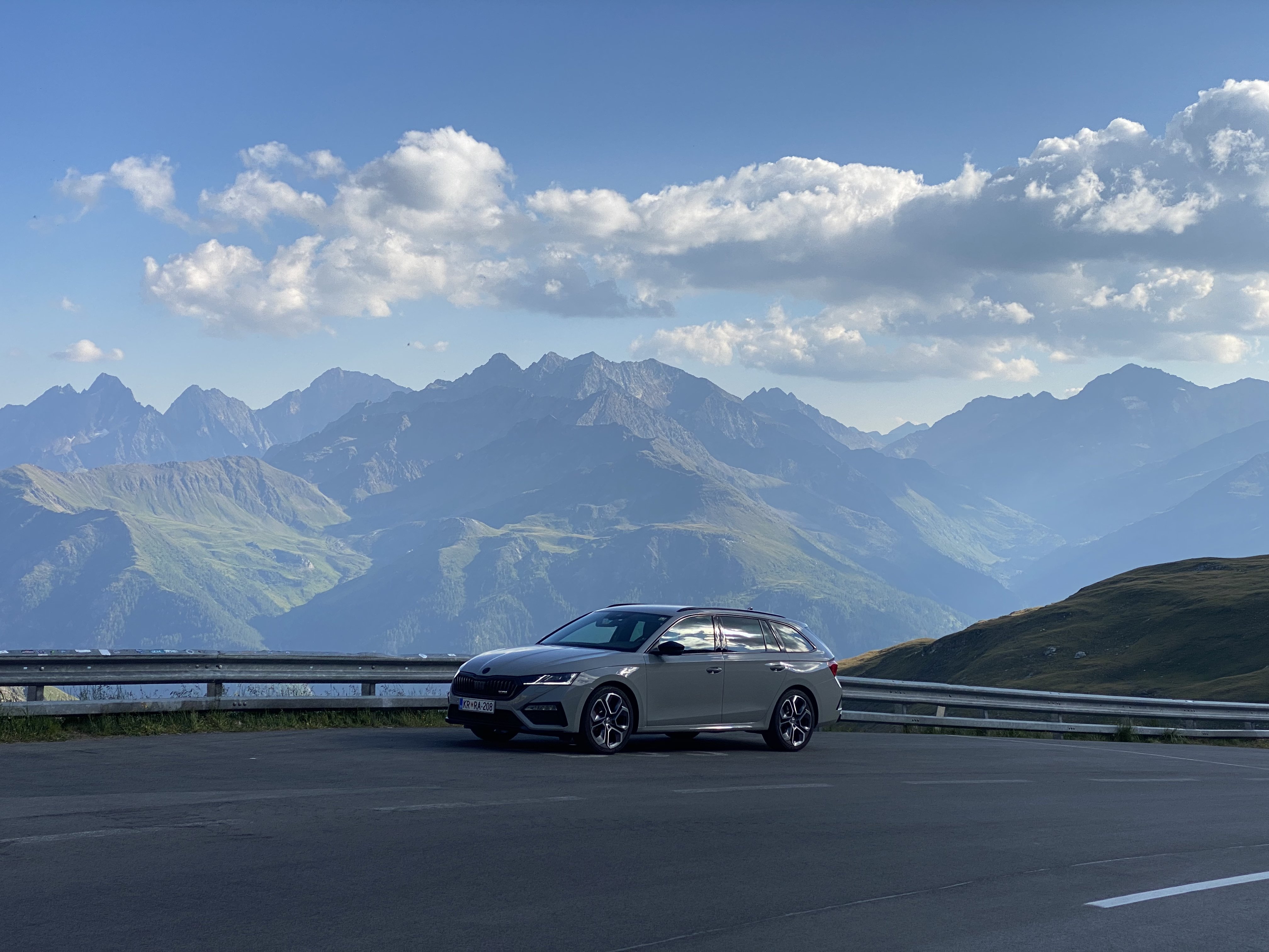
2 pointsAs this is my weekend fun car, it doesn't do a huge amount of miles, but when it does get used it tends to add hundreds of miles at a time/over a weekend. Last weekend, we went to York using motorways, dual carriageways, A and B roads. The car is everything I want from a weekend runabout, big enough for 2 people and their weekend luggage; comfortable enough with excellent handling on the coilovers; economical enough (average 52 mpg over the weekend trip); and definitely fast enough! Absolutely loving it at the moment, and the fact that very few people know what it is means I rarely get bothered by the boy racer brigade. Here it is parked up at our hideaway for the weekend.2 points
-
2 pointsThey have 'updated' them to Cross Climate 2, but that was way before February I think? They are 94 Y rated so higher speed rating... not that you'll get there 😉 Virtually identical tread from visual appearance. Black Circles have them for £101.87 each today, fitted locally (there's a 15% off code).2 points
-
2 pointsSome info on wiring repairs SSP+871003+++Wiring+harness+inspection+and+repair.pdf2 points
-
2 pointsIt's easier (read faster) to remove air than add 👌 I presume you need higher pressure because when braking it will transfer the weight of the caravan/trailer into the car, and therefore onto the wheels. As @roottoot mentioned, if it feels really "off" then drop a little front pressure, but just beware under breaking it will transfer the energy forward.2 points
-
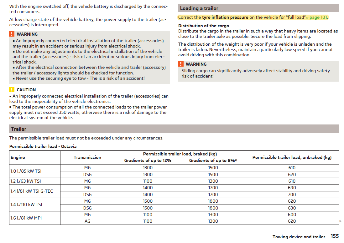
2 pointsThe manual states run the "full load" settings when towing, so whatever is in your fuel filler flap (if not missing)
 2 points
 -
2 pointsSo it’s finally done. Unfortunately I had to get outta country to get it done as I couldn’t find any one competent to do it. Full facelift conversion including matrix headlights, tail lights and self driving options (traffic assist and travel assist) IMG_6094.MOV IMG_6095.MOV IMG_6093.MOV
 2 points
 -
2 pointsI await a motoring journalist driving an EV when the weather is really really hot & just keeping the AC off and cooking / sweating inside the car and finding out that really the AC on is not reducing the cars efficiency that much as in the miles per kWh, it is the ambient temp affecting the batteries which really prefer being driven about near 20*oC more than 30*oC.2 points
-
2 pointsYes and fuel has tanked here too, but actually you need to make ICE more expensive to buy new. Put the new car First year tax up steeply on all ICE cars, bar maybe a few very clean hybrids.2 points
-
2 pointsI'm going back to a mark 7 Golf GTI. I had one before and loved it, as did my wife. Our toddler daughter no longer requires half of the contents of our house when travelling so the tardis boot is never full anymore! I will miss the ability to look at almost any object and say, "Yes. That will fit in the car!"2 points
-
1 pointI made this guide for my wife after the windows and central locking stopped working. I hope others find it useful. Yeti-fuse-box-diagrams.pdf1 point
-
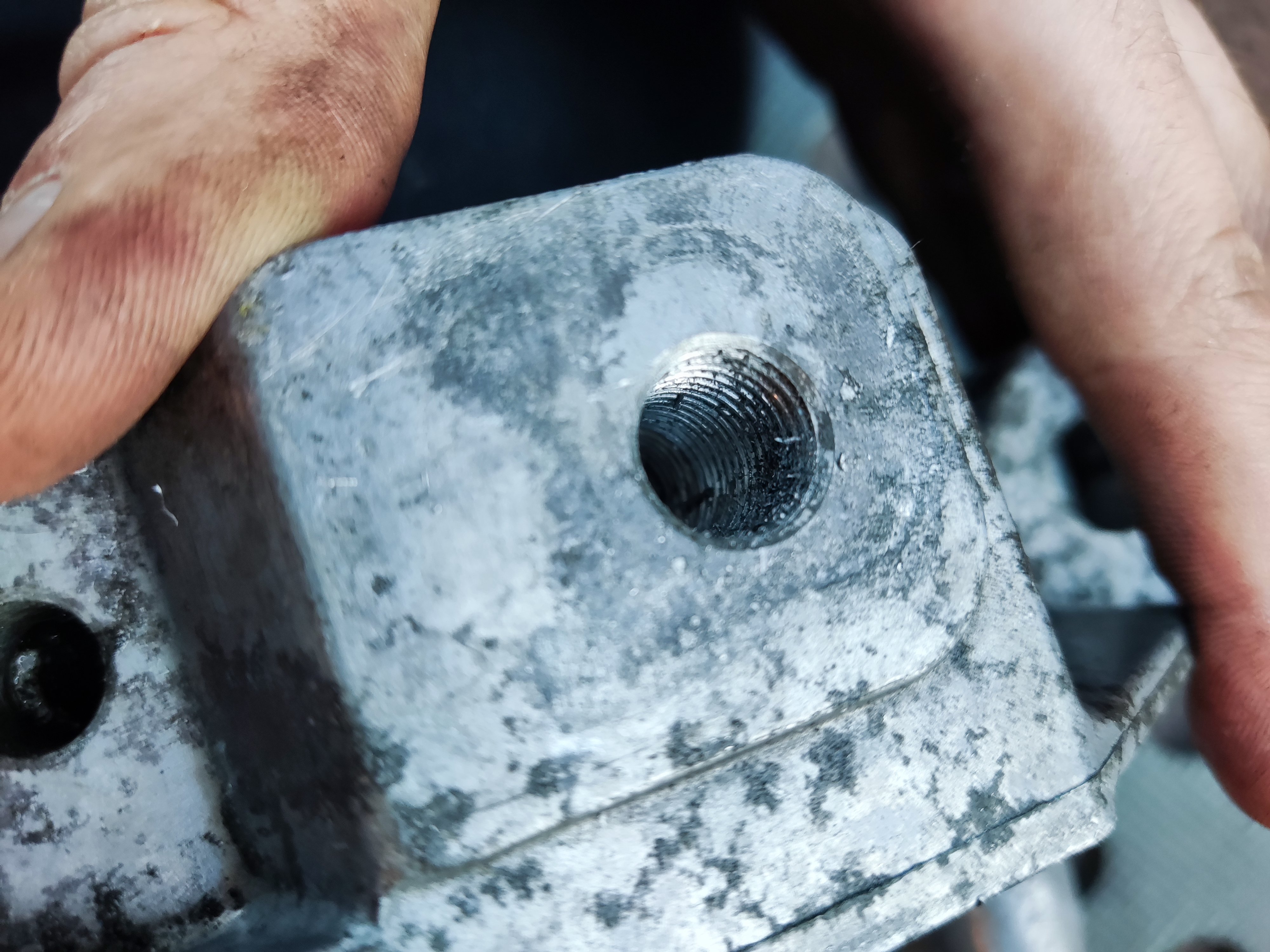
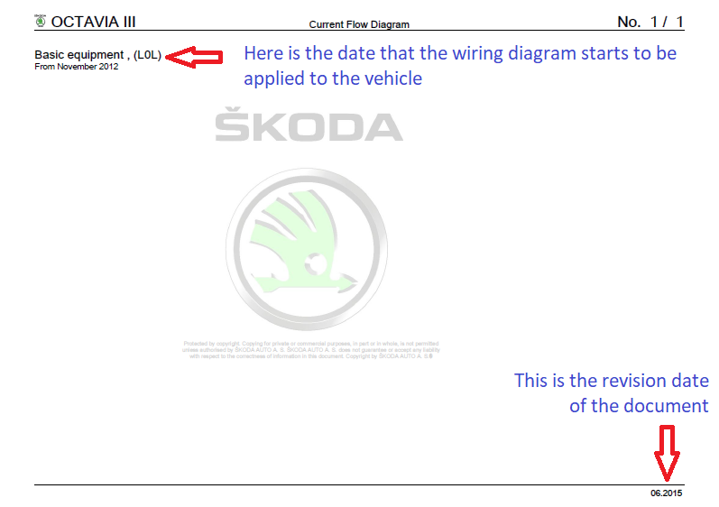
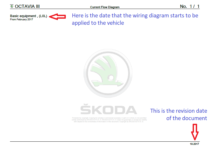
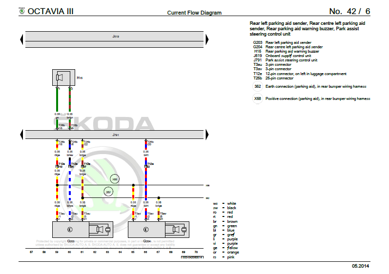
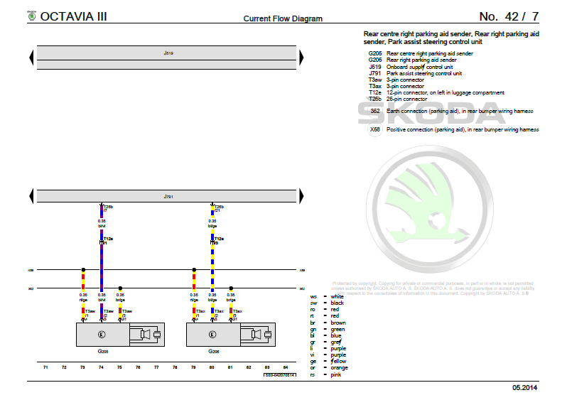
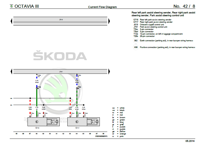
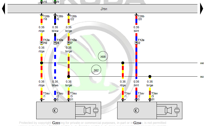
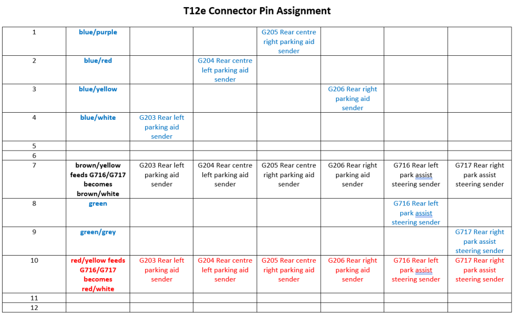
I am going to show you an example of a real life issue, and how you can then use this to locate and read the wiring diagram to help you trace faulty wiring. The car in question is a 2015 Skoda Octavia III Step 1: The car is scanned and we save this diagnostic session (because car history is important to keep) Address 10: Park/Steer Assist (J791) Labels:| 5Q0-919-298.clb Part No SW: 5Q0 919 298 K HW: 5Q0 919 298 Component: PARKHILFE PLA H12 0054 Revision: -------- Serial number: 39491514005930 Coding: 0131061041 Shop #: WSC 73430 790 00063 ASAM Dataset: EV_EPHVA2CAU3700000 003021 ROD: EV_EPHVA2CAU3700000_003.rod VCID: 47992422FE9974B74E-8012 3 Faults Found: 1079572 - Rear Right Parking Aid Sensors B1079 14 [009] - Open or Short to Ground Confirmed - Tested Since Memory Clear Freeze Frame: Fault Status: 00000001 Fault Priority: 3 Fault Frequency: 2 Reset counter: 98 Mileage: 222684 km Date: 2021.04.19 Time: 14:36:26 1079316 - Center Rear Right Parking Aid Sensor B1078 14 [009] - Open or Short to Ground Confirmed - Tested Since Memory Clear Freeze Frame: Fault Status: 00000001 Fault Priority: 3 Fault Frequency: 1 Reset counter: 2 Mileage: 222684 km Date: 2021.04.19 Time: 14:36:26 1080852 - Side Rear Right Parking Aid Sensors B107E 14 [009] - Open or Short to Ground Confirmed - Tested Since Memory Clear Freeze Frame: Fault Status: 00000001 Fault Priority: 3 Fault Frequency: 1 Reset counter: 2 Mileage: 222684 km Date: 2021.04.19 Time: 14:36:27 Step 2: We need to locate the correct wiring diagram, this is for an Octavia III 2015 car You will note from the next 2 pictures, that there exists two wiring diagram files from erWin website Here is the second file... As you can see from these two documents, the correct file we need to search though is our 1st document, as it "from November 2012" onwards Step 3: We now need to search the document for a keyword, or we need to use the bookmarks to find the correct section If you remember our diagnostic log, we can take the name of the control module scanned and use that as our keyword Address 10: Park/Steer Assist (J791) Labels:| 5Q0-919-298.clb For our example, we have J791 we can input into a search field on the document This takes us to this main section Step 4: We will now need to scan through the next few pages until we find the correct wiring diagram, which will depend on what is fitted to the vehicle The car in question has 6x rear parking sensors, and some of the pages only show wiring for 4x sensors! Diagram No. 42 / 6 This shows 2 of the 6 sensors, G203 and G204 Diagram No. 42 / 7 This shows the next pair of 2 sensors, G205 and G206 Diagram No. 42 / 8 This shows final 2 of the 6 sensors, G716 and G717 Step 5: Now the hardest part is tying all 3 wiring diagrams together. If we start with the basics, along the bottom row, each image has got a line, along with a row of numbers at the bottom, this is what ties one page into another so you can follow the trail of breadcrumbs so to speak. Diagram No. 42 / 6 Diagram No. 42 / 7 Diagram No. 42 / 8 So if you can imagine printing out all 3x pages, you would have to lay these 3x pages from left to right in a linear fashion. Step 6a: Now we need to examine and work out in our example, how each of the sensors is connected to the Park/Steer Assist (J791) module Taking a look at this small section: - Our module J791 is at the top, it connects towards our sensor via T26b connector (the numerical value = number of connections in the plug) T26b then connects to T12e 12-pin connector, on left in luggage compartment. Finally we have T3au that is the small 3-pin plug that connects onto the parking sensor itself Ok, so that was just one section of the wiring from the control unit J791 to just one sensor Now if we look at the 3x wires that head down to the sensor, we see on connector T3au/1 (left) and T3au/3 (right) two large black dots, along with a black horizontal line heading off to the right side of the image. The line coming from connector T3au/1 (left) has a large circled X68 Positive connection (parking aid), in rear bumper wiring harness This means that the wire coming from T12e/10 towards T3au/1 will have a "splice connection" where the single feed wire is split into two or more cables The line coming from connector T3au/3 (right) has a large circled 352 Earth connection (parking aid), in rear bumper wiring harness This means that the wire coming from T12e/10 towards T3au/3 will have a "splice connection" where the single feed wire is split into two or more cables I will add at the bottom of the thread, what a splice connection looks like in real life Step 6b: We now need to follow onto the next two pages of the documents to make note of what wires go where. Here is something that should be obvious, but best to point this out. The connector T12e is named so as it only has 12 maximum connections Each of the sensors has 3 wires feeding it Given that there are 6 sensors in total for this example vehicle, you can multiply 3 wires per sensor, and 6 sensors for a grand total of "18" wires Last time I checked, 18 wires cannot go into a 12 pin connector So this is why the little black dots on the wiring diagram and the circled X68 & 352 are important, they represent a splice in the wiring.


 1 point
 -
Rather than post every PR Code combo, here's how VAG measures pad thickness, and you can also see how many mm you can loose off the discs too So @JR RS you should be looking a min pad 2mm, as they don't include backing plate as specified. For comparison to above example from @roottoot here are VAG specs
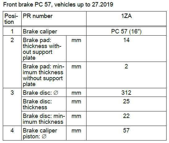
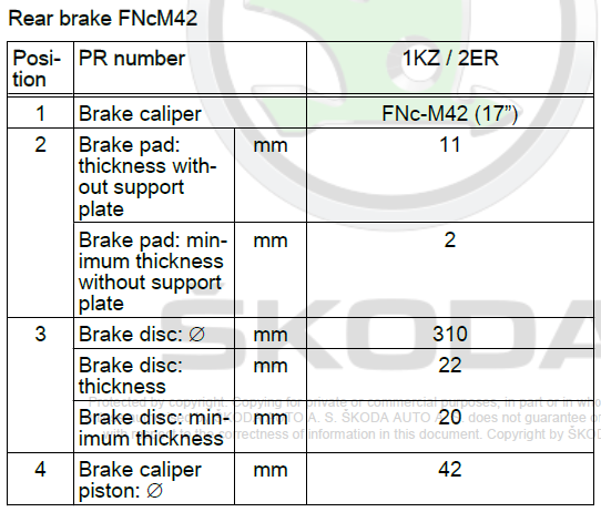 1 point
 -
When I had my 220 in for it's 75k kms service last week, they indicated the minimum brake thickness required is 3mm. Mine was measured at 7mm. So still plenty of life left in them after 64k kms1 point
-
1 pointNo problems, best of luck. You may wish to post any future faults in this location (if mods to move post) https://www.briskoda.net/forums/forum/235-skoda-octavia-mk-iii-2013-2020/1 point
-
1 pointIf airbag is enabled the "ON" light in orange lights up under the hazard light switch on every start for 65 seconds and if disabled lights up "OFF" in orange for all the time the engine is running.1 point
-
1 pointWhile the temperature was in the 30's I took it to the garage . The aircon was not working at all . The mechanic tested the gas gas levels while the aircon was switched to low , nothing . He pushed the censer connector and it worked. This has been the sole reason for it not working when hot. The contacts on the wiring connectors only made contact when cold. The mechanics opinion is that either the person who charged the system or the one who changed the cambelt disturb the connection.1 point
-
1 pointSo, I’ve got no further, battery light went off before I could double check codes to make sure I was right. Still be looking at everything and can’t work anything out apart from it saying reference voltage too low. Starting to give up hope of ever having power steering again at this point1 point
-
1 point
-
1 point
-
1 point@UrbanPanzer@Mickmartinor @thomasaspinmight be able to advise if they see this.1 point
-
1 point
-
1 pointI presume you are aware that passenger air bag light on is standard practice in all cars for at least the first 30 seconds...1 point
-
1 pointI have an iV with the tiny boot mounted tank fuel tank, I'll stick to filling up when the light comes on! I had the exact same issue in a rental Corsa on Tenerife. 150km indicated range. 15 minutes on the highway and suddenly the range is blank and the light was flashing angrily!1 point
-
1 pointFeel free to keep driving and let us know 😂😂😂 we’ll call it an experiment but in all seriousness I can see that being the case. I agree the trip counter is almost spot on most of the time. compared to the rental corsa I had which dropped 50 miles on the trip counter for a 10 mile journey1 point
-
1 pointWent for the V14 Gen 2 Intel i5 in the end as I eventually spotted it with a significant reduction - turned up today and looks to be a decent bit of kit1 point
-
1 pointSays 2.5 front and 3.2 rear so I will inflate to this even though only one passenger in back as it will have luggage etc in there.1 point
-
1 pointInteresting, thanks. TBH I don’t really see what the massive advantage of TSR is, as I’m not so decrepit (yet) that I don’t watch the road ahead and drive accordingly. Which is why I switch off lane assist as soon as I get in the car. But, I’m a sucker for techie stuff and if I can get TSR activated for a reasonable amount then I will.1 point
-
1 pointHow long have you had the car is very pertinent: Is this a new problem, or has your MPG always been like this? At 80K miles, I'm wondering how "full" the DPF is. Can you get that checked?1 point
-
1 pointA small update. Today I got my new oil delivered so I pulled out old oil using oil pump (i have no means of doing proper drain from underneath). My plan is to do another proper oil and filter change in October/November when I usually do it, this time its just oil to remedy immediate issue. So I pulled out a little bit less then, brace yourself, 6 L !!! Then I put in 4 L of fresh oil and dipstick was between middle and high. So I left it like that and went for a ride to drop my wife for work. I will keep monitoring oil levels and also try do do monthly longer runs on highway, even though highway is not my route and i have no reason to be on it, apart from freakin DPF as it seems. Would you guys advise me to reset my oil service interval today or should I leave it and let the mechanic reset when i do oil+filter change in couple of months?1 point
-
1 pointAutocar long-term review https://www.autocar.co.uk/car-review/long-term-reviews/cupra-born-2022-long-term-review1 point
-
1 pointI find the fuel indicator to be damped weirdly in these cars (and in the last two VAG cars I had before) It takes forever to drop from full, then quickly drops in the bottom half of the gauge. I'd just use the range indicator to plan your trips, it's normally reasonably accurate1 point
-
1 pointI was thinking of replacing my headlamps as they do look easy to replace. But I opted to clean them up in the end which made them look like brand new again.1 point
-
Same thing happened to me and I ended up with 2 new tyres across the axle for peace of mind. The cross climate has a specific feel and I wasn't willing to mess with the ballance. Strangely enough I went to V4S too. New ones on the back of course. The Goodyear has a winter lean compared to the summer lean of the Michelin so the "grippier" tyre should go on the back. Especially as it's new too.1 point
-
1 point
-
1 point
-
1 pointWell I paid £50 for the engine mount, £62 for the gearbox mount, £105 for all the poly bushes including the one I changed last time on the dog bone and £52 for all the bolts so £269 all together. Expense when you add it all up but cheaper than buying the aftermarket mounts like the 034 from awesome which works out to about £450. It took me slightly longer than it should because I forgot to mention I stripped the thread on the engine mount bracket and had to go get another from the breakers It took forever to get this part out and the replacement back in, anyone that has done a cambelt will know what I'm talking about. I've learnt a lesson about taking more care with bolts lining up properly. It's easily 3 hours work if nothing goes wrong. I need to take a look at the other bushes and the drop links now because there's a clonk when I go from left to right to left like going around an island for example, I did already change the antiroll bar bushes for rubber ones but I'll probably change them again for powerflex. Oh and I fitted a new fuel filter too

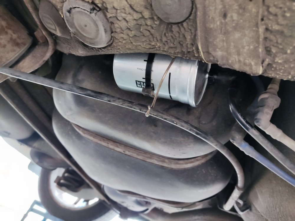 1 point
 -
It sounds like it is that. But you should dismiss possible cam and crank sensor fault. But combined with the noise it seems likely. I don't know that engine at all well, whats the engine code, shared with golf's I assume. But expect you'd be looking £700 plus as a finger in the air estimate. It will inevitably be charged higher than the scheduled diesel timing belts... Best to call a garage and ask for a quote. Better still make sure they diagnose the fault as the tensioner and camchain. Otherwise you'll have no comeback if it turns out to be not that!!1 point
-
None so far, watch out for someone whose first post is in this thread and says something along the lines of " Have any of you doubters actually tried it? I have and it really works!" That'll be a franchise owner...😁1 point
-
1 pointWhy would it? Not having a spare tyre is not a reason for an MoT failure.1 point
-
Credits to @Breezy_Pete & @JoeF for both posting this image This shows us an image of a single wire that is spliced into two wires Step 7: Here we have a tracing of all the wires in the loom from T12e to each of the 6x Sensors Red text is for the Positive (only 1 feed wire is Positive, T12e / 10) Black for Negative (only 1 feed wire is Negative, T12e / 7) Blue for Sensor data (T12e / 1-4, 8 & 9) Step 8: So how do we actually know where to look for a fault in the wiring loom? This is where you must combine the knowledge of the wiring diagram and also the fault codes that we scanned. If there was a fault in the main wiring loom from the module J791 via T26b (short to ground for example) then we can see that this would take out ALL 6 sensors, not just 3 out of the 6 Now we know that from T12e down to each sensor in turn is just 1 Positive feed, and 1 Negative feed wire, and where each of these 2x main feed wires then are spliced down towards each of the sensors. We can now disconnect connector T12e from inside of the boot on the left (behind tail light, inside the body) and check each sensor that is faulting, by disconnecting the wire and checking for continuity from T12e pin 10 to the Positive and Negative on each sensor. We can also visually inspect of course to see if any wires are cut, before we even have to probe any wires. In the above example, 3 of the 6 sensors cannot communicate. And checking the wires, breaks can be seen in some with corrosion, and also with some wires where no corrosion is seen, upon stripping the loom wires can be found to have been shorted out. Therefore, repair or replace this loom section (in this example, new loom fitted due to water ingress on some of the plugs)
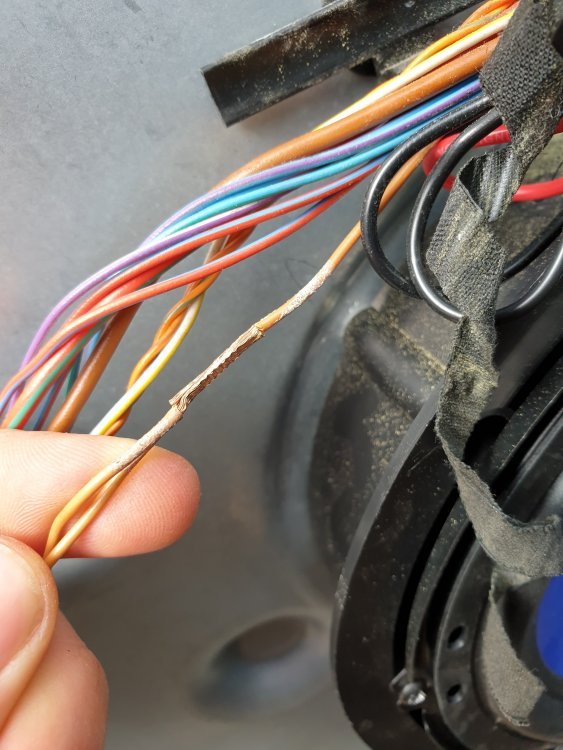
 1 point
 -
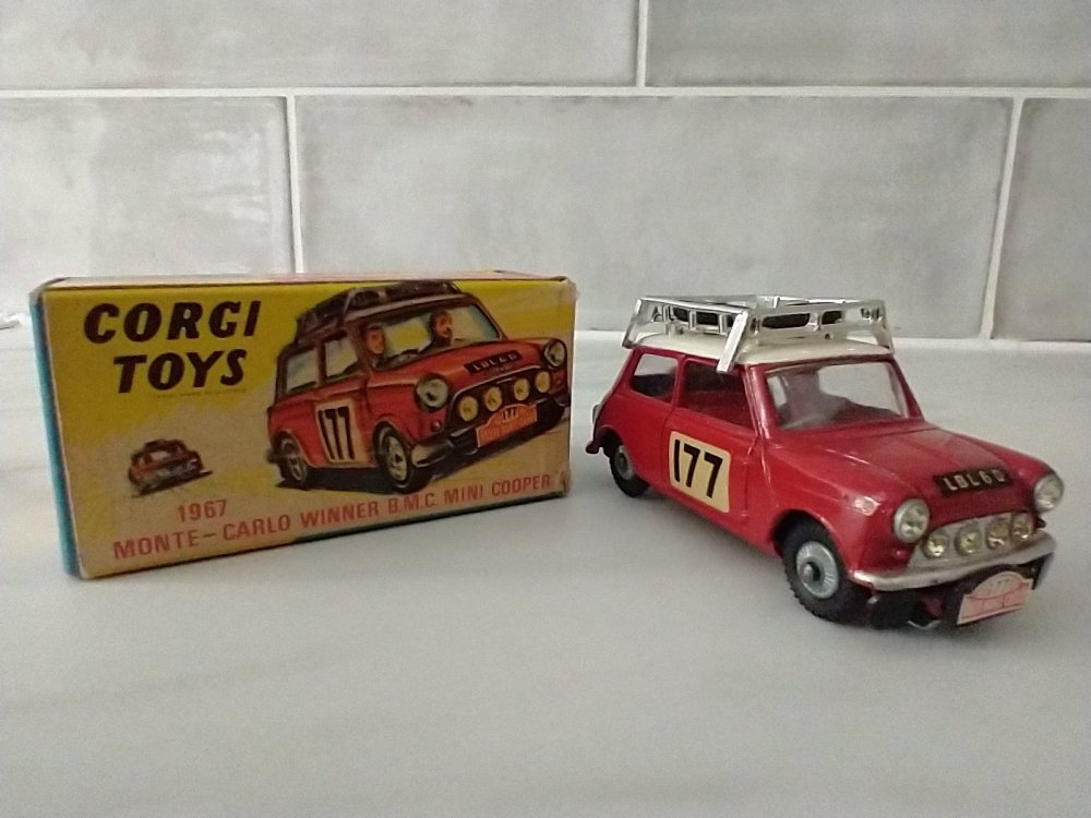
1 pointHis death reminded me that I had this from my youth. How many recent rally winners have a commemorative model car made of their exploits although this model is from the 1967 win of Rauno Aaltonen and Henry Liddon not Paddy's 1964 win. Rest in peace Paddy.
 1 point
 -
It was a good do! Some VERY nice motors around. Quite a few Skodas, and a lot of Mk2 Golfs and the like which are right up my street. I bobbed down with my dad and a couple of mates with my Octy and a fleet of Audi 90s.1 point
-
Hi guys I want to change shock absorbers and springs on mine. I passed 6 years of age and 280.xxxkm and still have the originals on as I know (I got the car when it was 3 years old). I will install Koni Actives. I asked some others if the original springs needed to be changed or not? (No damages or corrosion) but I guess I will anyway... I checked autodoc, eibach homepage and tried to search but as I can see almost all the pro kits will lower the car, I would like to avoid that... Anyone who is already went through the process and could helpe out to chose the right ones? No DCC in mine... Thanks in advance1 point
-
1 pointHi, Our Yeti is now 6 years old; last year it had the cambelt & water pump replaced together with service and MOT costing over £800. Last week it had a major service & MOT costing £432; with 30K on the clock it sailed through the MOT and no issues were found; DMK at Wakefield always look after it and it's never missed a beat whilst being a joy to own and drive; my wife and I love it; no chance of trading it for a car which these days looks like every other new car. Skoda made a huge mistake in dropping yeti production; we'd be now collecting our third Yeti and absolutely no way do we want a battery car. The government wanted owners in diesel cars a few years ago so we're in a diesel car and will stick with it; who wants to own a car that when the battery needs replacing it will be cheaper to scrap the car; this is progress? The only real expenditure other than servicing was to fit Michelin Cross Climate tyres because of our steep valley location; the tyres cost £600 a few years ago and were fitted by "Tyresonthedrive". DMK Wakefield always do a good job and our Yeti will never be taken to a back street garage to save a few quid; I was told if we did trade in our Yeti wouldn't touch the ground it would sell so quickly; it's in excellent condition and I'd like to have it fully rustproofed which I need to look into rather than bother trying to do it myself; it's the best car we've ever had the pleasure to own and it's a keeper. Kind regards, Colin.1 point
-
1 point
-
1 pointAgree with everyone else. That's not for repairing in my opinion. Regardless of whether it's holding air, the tyre is damaged and structurally compromised. A potential blow-out waiting to happen. Gaz1 point
-
1 pointNO!! A cut like you illustrate will have taken all the strength out of the tyre sidewall, and I doubt it is either legal or safe to use ever again.1 point


.thumb.jpg.683fc09a88a36e3a8a88cc4faae6baa4.jpg)